Amplitec C23S-EGSM User manual

23dBm Single Wide Band Repeater
C23S-EGSM User Manual
Notes: Thank you for purchasing our product.
Please read carefully the manual before installation

Chapter 1 - Safety Warning
Users must follow the below principles:
1. Repeater should follow system requirement of
communication equipment, assure good groundings and
lightning protection.
2. The power supply voltage of repeater should meet the
standards of security requirement; any
repeater-operator can operate only after cutting power in
advance. Only the professional can operate electrified.
3. Do not dismantle machine, maintain or displace
accessories by yourself, because in this way, the
equipment may be damaged or even get an electric
shock.
4. Do not open the repeater, touch the module of repeater,
even not to open the cover of module to touch the
electronic component, the components will be damaged
due to electrostatic
5. Please keep away from heating-equipment, because the
repeater will dissipate heat when working. And do not
cover repeater with anything that influences
heat-dissipation.

Chapter 2 - Summary
In mobile communication, it is inevitable that macro-cell coverage cannot cover
weak or dead zones; to use repeater is a good choice in these areas. These
band selective repeaters mainly applied in covering small blind and weak
zones.
Nowadays, wireless repeaters are widely used in solving coverage questions
of weak signal and blind signal. As for our dual band repeater, with its stale
function, low noise, high gain, small power consumption, it not only could
amplify signal well, solve poor coverage but also reduce the ambient noise,
reduce radiation and prolong using life. They are used in places such as
mountain settlements, scenics, shopping malls, hotels, airports, piers, bus
stations, stadiums, entertainment halls, railways, tunnels, high-ways, islands
and so on. At the same time, the repeaters are still working flexibility in traffic
diversion and BTS networking adjustment and other issues.
Figure 2.1 Wireless repeater application diagram
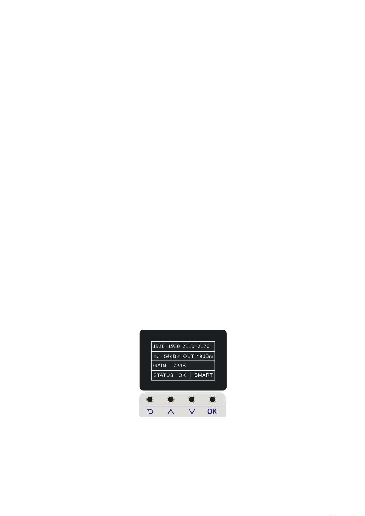
The C23S single band repeaters are suitable to solve poor signal and blind
area coverage problems of medium-small areas. Because of its smart design,
good band rejection, display function for easier project setting and fast setting
and debugging, it is quite popular for customers.

Chapter 3 - Standard and Specification
3.1 Product description
Repeater is essentially a same frequency, transparent and amplify equipment.
Inside the single system repeater there are two independent amplify link
roads---Up Link and Down Link. DL gets the RF signal by donor antenna from
the BTS, amplifies the signal and then transmits to the area to be covered
through the coverage antenna. At the same time, the UL receives the RF
signal from the mobile station by coverage antenna, amplifies the signal and
then transmits back to the BTS by donor antenna.
3.2 Product Feature
The display shows very clearly of all display devices and the button function
are more intuitively and faster
Could support dual mobile communication network
Low power consumption, low interference
ALC could limit the output power to ensure stable coverage
Frequency power display function can keep abreast of real-time signal
strength
Manual gain attenuation, with 1dB steep to attenuate the gain among 1-31dB
range
Isolation auto detection and adjustment, AGC auto control, install with one
button which is much more easier for project setting, could install and debug
quickly;
Apply for medium and small areas coverage, such as VIP room, meeting
room, office, bedroom, apartment, hotel, parking lot and so on.

3.3 System Schematic
Figure 3.3.1 the Schematic of the repeater
3.4 Electric Specifications
Items
Uplink
Downlink
Frequency Range
880 ~ 915 MHz
925 ~ 960 MHz
Output Power(CW)
23±2 dBm
23±2 dBm
Gain
73±2 dB
73±2 dB
Ripple
≤15 dB
≤15 dB
Noise Figure @ max. gain
≤8 dB
≤8 dB
ATT
step of 1 dB
1~10 dB
∣△∣≤1 dB
∣△∣≤1 dB
10~20 dB
∣△∣≤1 dB
∣△∣≤1 dB
20~25 dB
∣△∣≤1.5 dB
∣△∣≤1.5 dB
ALC Active 10dB
∣△∣≤2 dB
∣△∣≤2 dB
VSWR
≤2
≤2
Intermodulation Products
≤-36 dBc
≤-36dBc

Items
Uplink
Downlink
Spurious Emission
9KHz~1GHz
≤-36 dBm
≤-36 dBm
1GHz~12.75GHz
≤-30 dBm
≤-30 dBm
Time Delay
≤0.5 μs
≤0.5 μs
Power Supply
DC:12V
Power Consumption
< 15W
RF Connector
N-Female
Environment Conditions
IP40
Humidity
< 90%
Operating Temperature
-10℃~ +55℃
3.5 Machine Specifications
RF Connector
N-Female
Cooling
Heatsink Convection cooling
Environment Conditions
IP40
Humidity
< 90%
Operating Temperature
-10℃~+55℃

3.6 Appearance and function keys
Figure 3.6.1 repeater display, control panel and ports
A
G
H
F
C
B
D
E
I

A:Donor antenna port (N-female)
B:Coverage antenna port(N-female)
C:12V DC power supply port
D:Return button
E:Up button
F:Down button
G:OK button
H:Display screen
I:Grounding screw
3.7 Function Key Operation
Functions on Control Panel:
Return button: Return to upper-level menu
Up button: select from down to up
Down button: select from up to down
Ok button: to confirm.
Display Screen
After powering on, it will scroll display real-time working frequencies, downlink
input and output power, gain and alarm etc (as shown in Figure 3.7.2.1).
Figure 3.7.2.1

To view the working frequencies
Move the cursor to the first line with up or down button (as shown in Figure
3.7.3.1), and press OK button to enter the working frequencies display
interface (as shown in Figure 3.7.3.2). Press the return button back to the main
menu.
Figure 3.7.3.1 Figure 3.7.3.2
ATT Setting.
By default, the system is in Smart mode, so it will automatically adjust the ATT,
manual operation is not allowed; if you want to set ATT, please change it to
Manual mode by moving the cursor with up or down button to the forth line
“STATUS”, then press OK (as shown in Figure 3.7.6.1), then navigate the
cursor to “MODE” (as shown in Figure 3.7.6.2)
Figure 3.7.6.1 Figure 3.7.6.2

Press OK to enter, “SMART” is on the left and “MANUAL” is on the right, select
“MANUAL” with up or down button and press OK (as shown in Figure 3.7.6.3).
Figure 3.7.6.3
Then move the cursor to the third line “Gain ” with up or down button (as
shown in Figure 3.7.6.4), press OK to enter the ATT setting interface, then
select one system, press OK(as shown in Figure 3.7.6.5).
Figure 3.7.6.4 Figure 3.7.6.5
To increase or decrease the gain value, please press the up or down button
(as shown in Figure 3.7.6.6 and 3.7.6.7); Max. adjustment range is 32dB, the
system’s uplink and downlink will be adjusted at the same time. After
adjustment, press the return button back to the main menu.

Figure 3.7.6.6 Figure 3.7.6.7
View Alarm.
Move the cursor to the forth line “STATUS”from main menu, then press OK
to enter (as shown in Figure 3.7.7.1), then navigate the cursor to “ALARM
ITEMS” with up or down button (as shown in Figure 3.7.7.2).
Figure 3.7.7.1 Figure 3.7.7.2
Then press Ok to view, select AGC (as shown in Figure 3.7.7.3), press OK to
view AGC alarm (as shown in Figure 3.7.7.4).
Figure 3.7.7.3 Figure 3.7.7.4

Select DL OUTPUT (as shown in Figure 3.7.7.5), press OK to view DL
OUTPUT alarm (as shown in Figure 3.7.7.6).
Figure 3.7.7.5 Figure 3.7.7.6
To remove alarm, if it is in Smart mode, the device will make adjustment
automatically after re-powering; if it is in Manual mode, you should adjust the
outdoor antenna and the gain manually. If all is in OK status, that means it
works normally. Press the return button back to main menu after adjustment.
Restore Factory Settings
Move the cursor to the forth line “STATUS”with up or down button (as shown
in Figure 3.21), then press OK to enter, then navigate the cursor to
“DEFAULTS”
with up or down button (as shown in Figure 3.22), press OK to
restore to factory setting; factory settings by default is in Smart mode.
Figure3.7.8.1 Figure3.7.8.2

After restoring to factory setting, it will detect ISO automatically. To view ISO,
move the cursor to the forth line “STATUS”, press OK, and select “ISOLATION”
(as shown in Figure 3.7.8.3), then press OK to view ISO (as shown in Figure
3.7.8.4). After that, press the return button back to main menu.
Figure3.7.8.3 Figure3.7.8.4

Chapter 4 Installation
4.1 Installation requirements
Before install or operate this repeater, please read the first chapter “safety
instructions” carefully. Please make sure the grounding wire is firmly grounded
and the power cord is firmly connected before power on the device.
Environment requirements.
It should be installed in a space where there is no corrosive gas and smoke or
liquid leakage.
It should be installed on wall that is waterproof, under thunder protection,
with sun block and good ventilation.
It should be installed at a height that is easy for cabling, with good heat
dissipation, safe and easy to maintain.
It should be installed in a place with stable and independent power supply.
Installation tools
No.
Items
Quantity
Remarks
1
Percussion drill
1
Drill holes on wall, self-provided
2
spanner
1
Reinforce the interface connection,
self-provided
3
Expand plug,
screw
4
respectively
Fasten the device, delivered with the device
4
Mobile phone for
testing
1
Test the effect of the device, self-provided
5
Multimeter
1
Test voltage and wiring condition,
self-provided
6
screwdriver
1
Tighten or fasten the device, self-provided
7
Waterproof tape
some
Prevent water to leak into the feeder interface,
self-provided
4.2 Installation steps
This repeater should be installed on a hard, firm and flat surface, its installation
steps are as follows:

Select a proper installation site according to the size and installation
requirements of the repeater.
Drill holes with percussion drill according to the position of the shell holes, pore
size isΦ7 and the hole location is as follows(unit: mm).
Mounting Hole Dimensions
Put theΦ8 expand plug into the 4 holes.
Align the fixing holes of the repeater with corresponding holes on the wall as
shown in Figure 4.2.1, and drive 4 M6*40 screws into the expand plugs with
screwdriver and fasten the repeater firmly.
Put the repeater upward onto the shell as shown in Figure 4.2.2.
Figure 4.2.2 repeater installation

4.3 External connections
Repeater Ports
Ports of the repeater are shown in Figure 4.3.1. Please do not power on the
repeater until the feeder is connected. The installation of antenna should be
designed and conducted by professional personnel. When connecting feeder,
please wrap the interface with waterproof tape to prevent water into the
repeater. The interface can be fastened by wrench. Before power on, please
measure the repeater voltage with multimeter to make sure the input voltage is
within the standard range. External connection of the repeater is as follows:
BTS:Connecting feeder of the donor antenna;
MS:Connecting feeder of the coverage antenna;
DC+12V :connecting with power adapter matched with the repeater. The
rated input AC of the power adapter is 220V/50~60Hz, AC power supply
GND

range 100~240V, frequency range 50~60Hz. Output DC is 12V 2A.
GND:grounding.
4.4 Start the Repeater
Figure 4.4 repeater display and its control panel
After ensuring that the repeater is installed properly, that power supply and
GND meet the requirements, turn on the repeater. After 5 seconds, repeater
initialization is completed and it enters the normal working state.
Observe and adjust alarm display (methods of adjustment, please refer to
section 3.6 of this manual)
If alarm is not removed with correct adjustment methods, please contact your
supplier.
After test the effect of the repeater with test mobile phone, the procedure of
repeater installation is completed.

Chapter 5 Maintenance
5.1 Operation and maintenance
Power supply
Please make sure the voltage and frequency of AC power is in conformity
with that of the repeater.
Component replacement
Please do not maintain or replace the components by yourself, in case you
may get an electric shock. Only authorized personnel can maintain or replace
the components.
Waterproof and moisture-proof
Please do not turn on or off the repeater in moist environment when its door
is open.
5.2 Attentions
Switch-off is recommended during the following situations:
Power supply is abnormal.
Liquid flows into the device.
Working conditions is abnormal such as overheating, strange smell or foreign
matters
Performance is decreased
Near to fire
Table of contents
Other Amplitec Repeater manuals

Amplitec
Amplitec C10 Series User manual

Amplitec
Amplitec C15-WCDMA User manual

Amplitec
Amplitec C10 Series User manual

Amplitec
Amplitec W20-GSM User manual

Amplitec
Amplitec C23S Series User manual

Amplitec
Amplitec C20W Series User manual

Amplitec
Amplitec C20M-5B Series User manual

Amplitec
Amplitec C23S Series User manual