CombiSteel 7455.0170 User manual

Hand Mixer
7455.0170 - 7455.0175 - 7455.0180 - 7455.0185
Whisk for Hand Mixer
7455.0190
User Manual
Gebruikershandleiding
Gebrauchsanweisung
Le mode d’emploi

2
www.combisteel.com
CONTENT
ENGLISH
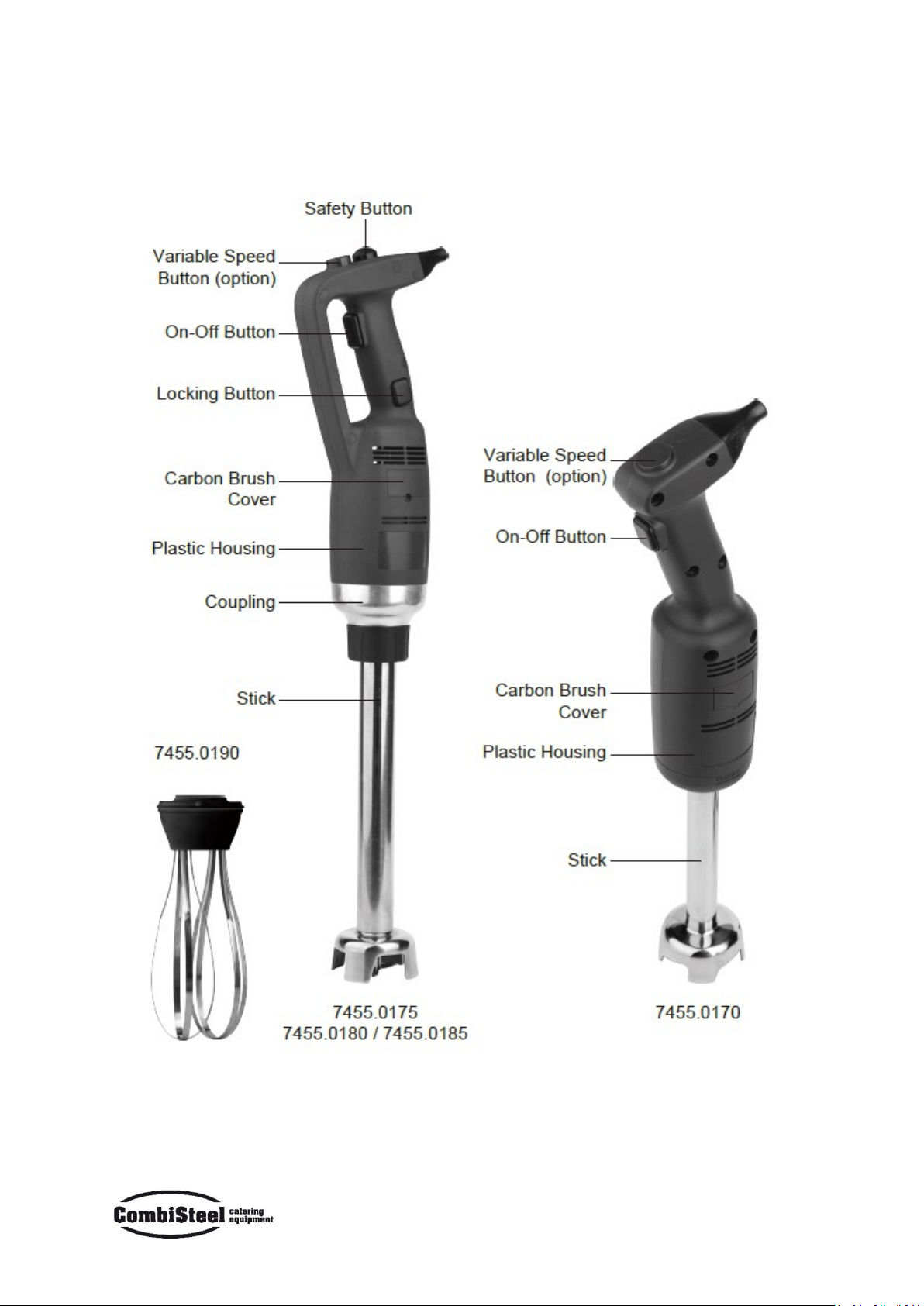
HAND MIXER........................................................................................................................................................... 4
MAIN TECHNICAL PARAMTERS ............................................................................................................................... 5
INTRODUCTION ...................................................................................................................................................... 6
OPERATING INSTRUCTIONS .................................................................................................................................... 6
STARTING AND STOPPING THE BLENDER............................................................................................................6
CONTINUOUS OPERATION:................................................................................................................................. 6
VARIABLE-SPEED OPERATION .............................................................................................................................6
WORKING POSITION ........................................................................................................................................... 7
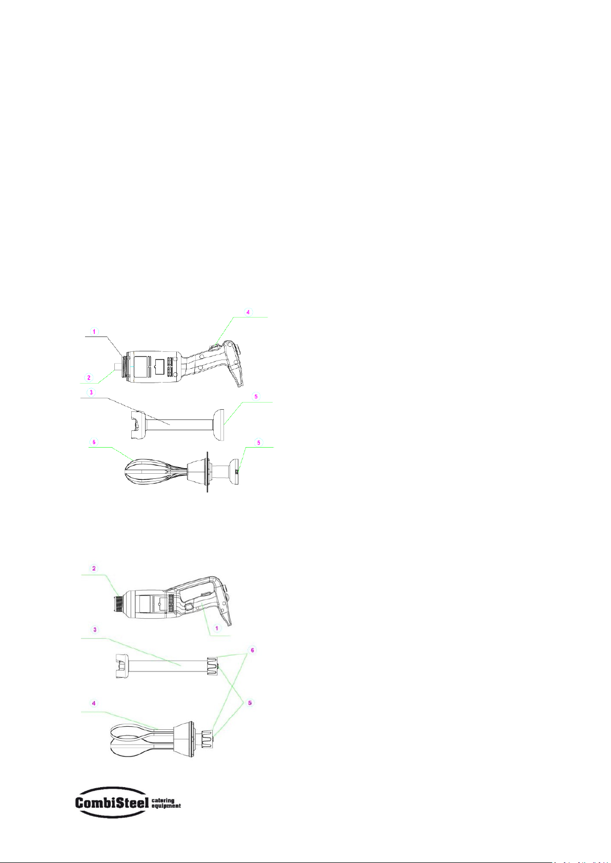
ASSEMBLING / DISMANTLING ............................................................................................................................ 7
CLEANING INSTRUCTIONS ......................................................................................................................................8
TROUBLESHOOTING................................................................................................................................................8
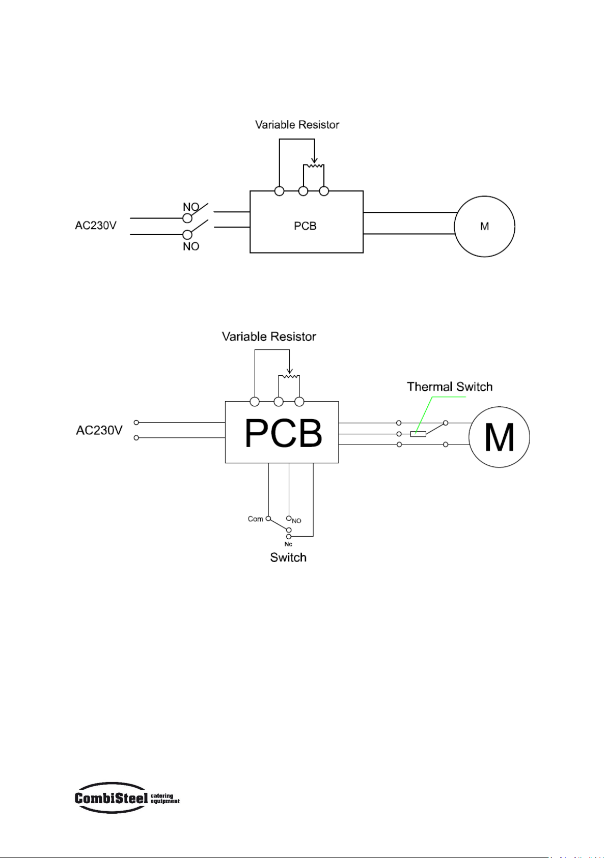
CIRCUIT DIAGRAM .................................................................................................................................................. 9
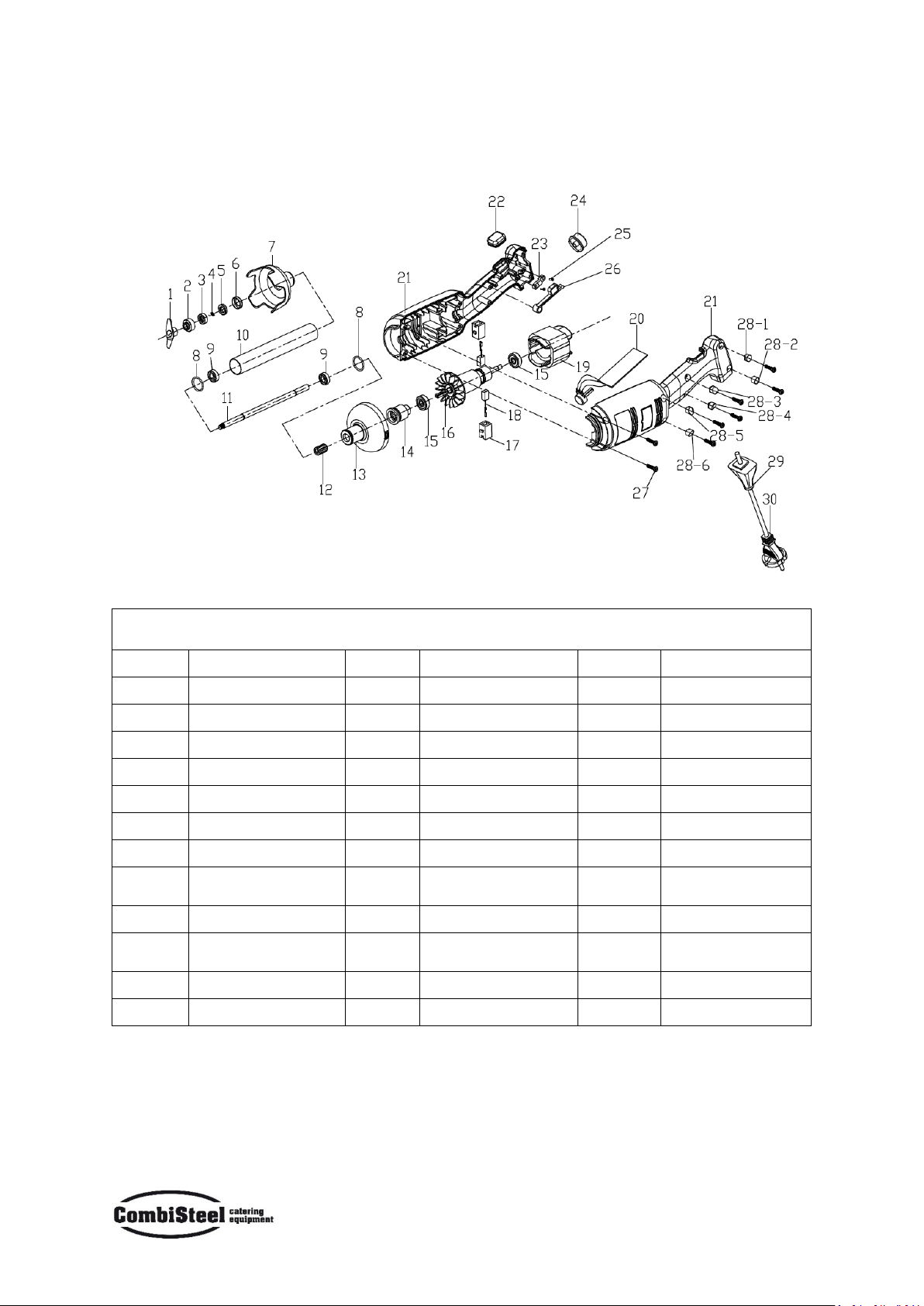
EXPLODED VIEW & SPARE PART LIST .................................................................................................................... 10
NEDERLANDS
HANDMIXER.......................................................................................................................................................... 14
BELANGRIJKSTE TECHNISCHE PARAMETERS......................................................................................................... 15
INLEIDING ............................................................................................................................................................. 16
GEBRUIKSAANWIJZING ......................................................................................................................................... 16
STARTEN EN STOPPEN VAN DE BLENDER.......................................................................................................... 16
LANGDURIGE BEDIENING: ................................................................................................................................16
VARIABELE SNELHEID BEDIENING..................................................................................................................... 16
WERKPOSITIE .................................................................................................................................................... 17
MONTAGE/DEMONTAGE .................................................................................................................................. 17
REINIGINGSINSTRUCTIES ...................................................................................................................................... 18
PROBLEEMOPLOSSING .........................................................................................................................................18
SCHAKELSCHEMA.................................................................................................................................................. 19
DETAIL OVERZICHT & RESERVEONDERDELEN LIJST ..............................................................................................20
DEUTSCH
STABMIXER............................................................................................................................................................ 24
TECHNISCHE HAUPTPARAMETER..........................................................................................................................25
EINFÜHRUNG........................................................................................................................................................ 26
BETRIEBSANLEITUNG............................................................................................................................................ 26
STARTEN UND STOPPEN DES MIXERS ...............................................................................................................26
DAUERBETRIEB: ................................................................................................................................................ 26
BETRIEB MIT VARIABLER GESCHWINDIGKEIT ...................................................................................................26
ARBEITSPOSITION ............................................................................................................................................. 27
ZUSAMMENSETZEN / ZERLEGEN ......................................................................................................................27
REINIGUNGSINSTRUKTIONEN............................................................................................................................... 28
FEHLERSUCHE UND -BEHEBUNG ..........................................................................................................................28
SCHALTPLAN ......................................................................................................................................................... 29
TEILELISTE .............................................................................................................................................................30

3
www.combisteel.com
FRANÇAIS
MÉLANGEUR À MAIN............................................................................................................................................34
PRINCIPAUX PARAMÈTRES TECHNIQUES .............................................................................................................. 35
INTRODUCTION .................................................................................................................................................... 36
MODE D'EMPLOI...................................................................................................................................................36
DÉMARRAGE ET ARRÊT DU MÉLANGEUR ......................................................................................................... 36
OPÉRATION CONTINUE:....................................................................................................................................36
FONCTIONNEMENT À VITESSE VARIABLE .........................................................................................................36
POSITION DE TRAVAIL ....................................................................................................................................... 37
ASSEMBLAGE / DÉMONTAGE............................................................................................................................ 37
INSTRUCTIONS DE NETTOYAGE............................................................................................................................. 38
DÉPANNAGE..........................................................................................................................................................38
SCHÉMA................................................................................................................................................................ 39
VUE EXPLICITE ET LISTE DES PIÈCES DE RECHANGE.............................................................................................. 40

4
www.combisteel.com
HAND MIXER

5
www.combisteel.com
MAIN TECHNICAL PARAMTERS
MODEL
VOLTAGE
POWER
SPEED
BODY
WEIGHT
A
LENGTH
(mm)
B
DIAMETER
(mm)
7455.0170
230V~/50Hz
220W
15000 RPM
1.1 KG
304
75
7455.0175
230V~/50Hz
350W
2000-13000 RPM
2.5 KG
359
91
7455.0180
230V~/50Hz
500W
2000-14000 RPM
3.1 KG
359
91
7455.0185
230V~/50Hz
500W
2000-14000 RPM
3.1 KG
359
91
NOTE:
The machines above don’t include any of the following attachments. In the chart below you can find available
attachments for your choice.
MODEL
WEIGHT
C
LENGTH (mm)
D
DIAMETER (mm)
DESCRIPTION
7455.0190
0.5 KG
250
/
SUIT FOR MACHINE 7455.0175 /
7455.0180 / 7455.0185

6
www.combisteel.com
INTRODUCTION
1. We advise you to carefully read the instruction included in this package.
2. If you wish to make the best use of the Immersion Blender and all its possibilities, you must be thoroughly
familiar with its performance and operating features.
3. Maintenance requires just a few simple operations that may be carried out by the operator.
4. To ensure a long life and minimize operating costs, you should carefully follow the rules given in this manual.
5. The manufacturer has designed the Immersion Blender to ensure safe operating conditions:
Exclusion or removal of the safety features installed by the manufacturer will seriously undermine the
guaranteed safety conditions.
6. To ensure these conditions you must also fully comply with the instructions regarding the installation and
power supply of the Immersion Blender.
7. The Immersion Blender must be installed in a work environment free of corrosive agents.
8. The installation site must not be subject to explosion.
9. Use only original SPARE PARTS.
10. This manual instruction is an integral part of the Immersion Blender and must be kept in a safe place. The
features, information and drawings published in this manual are the exclusive property of the manufacturer.
11. The appliance’s functions make it possible to carry out all types of processing in the minimum of time with
below recommended food: thick vegetable, soups, mashed potatoes, creams, batters, mayonnaise, almonds pulp,
cream cheese and other similar foods.
OPERATING INSTRUCTIONS
CAUTION: Before connecting your units to the power supply, make sure the machine’s electrical specifications,
printed in the unit’s rating plate, meet your local power supply.
STARTING AND STOPPING THE BLENDER
1. Check that the on-off button (No.3) is in the released position.
2. Connect the appliance to the power supply.
3. Insert the stick or whisk into the appliance.
4. Press and hold down the safety button (No.1) if the appliance has
one.
5. Press the on-off button (No.3), and the blender will start up.
6. To stop the blender, release the on-off button (No.1) and then the
safety button (No.1) will release automatically.
CONTINUOUS OPERATION:
Follow steps 1 to 5 above, then:
6. While the on-off button (No.3) is in the depressed position, press the locking button (No.4).
7. Release the on-off button (No.3), and the appliance will function continuously.
8. To stop the appliance, press and release the on-off button (No.3).
VARIABLE-SPEED OPERATION
Follow steps 1 to 5 above, then:
9. Change the speed of the motor by turning the variable speed button (No.2) towards the maximum or minimum
as required. It is advisable to start at a low speed when using the whisk. With the self-regulating speed system,
once you have selected a speed, it will remain constant, even if the consistency of your mixture changes.

7
www.combisteel.com
WORKING POSITION
Blender function: For greater control, we recommend that you hold the bender by the handle and the bottom
of the motor unit. Furthermore, we recommend that you tilt the blender at a slight angle to prevent the bell
from touching the bottom of the container. Always make sure that the bell is sufficiently immersed to avoid
splashing and that the air vents of the motor unit do not come into contact with any liquids. For optimal efficiency,
two thirds of the stick should be immersed in the preparation.
Whisk function: You can also hold the appliance by the handle with one hand, leaving the other hand free to
hold the bowl, if necessary. While you process the preparation, we recommend that you move the whisk around
in the bowl, in order to ensure that the mixture is completely homogeneous. We strongly advise you to keep the
whisk from touching the sides of the bowl. For Maximum efficiency, at least one-fifth of the whisk length should
be immersed. But never immerse the whisk holder into the preparation.
ASSEMBLING / DISMANTLING
The assembly / disassembly operations of every part of the appliance are performed with the appliance
stopped and with the plug disconnected from the socket.
Assembly Model 7455.0170:
1. Align and insert the coupling (5) of the stick (3) or whisk (6) in the clutch (2) of the machine body (1).
2. Screw the stick (3) or whisk (3) up to fasten it firmly to the machine body (1).
Assembly Model 7455.0175, 7455.0180, 7455.0185:
1. Align and insert the coupling (5) of stick (3) or whisk (4) in the clutch (2) of the machine body (1). Be sure the
concave side of coupling catches into the convex of the clutch.
2. Screw the nut (6) up to fasten them firmly to the machine body (1).

8
www.combisteel.com
The disassembly activities are performed in the opposite way than what described in the assembly phases.
CLEANING INSTRUCTIONS
As a precaution, always unplug your appliance before cleaning it.
1. After using the Immersion Blender and Whisk in a hot preparation, cool the bottom of the stick in cold water
before dismantling the bell from the stick. After completion of preparation, clean immediately to prevent food
from sticking to surfaces.
2. Never put the motor unit and its handle in water, clean them with a damp cloth or a sponge.
3. Blender Stick and Bell cleaning: Place the stick and bell into a suitable container with clean water and switch
on for a few seconds to clean the bell and stick. WARNING: Always dry the blades thoroughly after cleaning to
avoid spotting.
4. Never immerse the whisk holder in water, clean it with a slightly damp cloth or sponge.
5. It is vital to clean it thoroughly between each job using a detergent or disinfectant, but never use pure bleach.
For plastic parts, do not use detergents that are too alkaline.
TROUBLESHOOTING
If it is due to a power cut or if the appliance has been unplugged, release the on-off button (No.3), check the
power supply and then restart the appliance.
If it is due to overheating of the machine, release the on-off button (CB), and then unplug the appliance, wait a
few minutes for the motor to cool down and the thermal safety mechanism to be at reset, and then restart the
appliance.
If you cannot locate the cause of the problem: release the on-off button (CB), unplug the appliance, check:
1. the plug
2. that the blades are free to rotate in the bell,
3. that state of the power cord,
4. that drive shaft is free to rotate. To do this, remove the bell and test the rotation of the end of drive shaft
manually.
If a malfunction occurs which is not on our list of possible faults, consult your retailer or return the appliance to
the after-sales services.

9
www.combisteel.com
CIRCUIT DIAGRAM
7455.0170
7455.0175 / 7455.0180 / 7455.0185

10
www.combisteel.com
EXPLODED VIEW & SPARE PART LIST
7455.0170
7455.0170 SPARE PART LIST
Part no.
Part name
Part no.
Part name
Part no.
Part name
1
Blade
13
Plastic head housing
25
Pressing board screw
2
Convex ring
14
Spline sleeve
26
Switch osculant staff
3
Graphite ring spring
15
Bearing
27
Housing screw
4
Graphite ring
16
Rotor
28-1
Screw plunger 28-1
5
Ceramic ring
17
Brush rack
28-2
Screw plunger 28-2
6
Ceramic ring sleeve
18
Brush
28-3
Screw plunger 28-3
7
Knife protector
19
Stator
28-4
Screw plunger 28-4
8
Seal ring
20
PCB speed control
board
28-5
Screw plunger 28-5
9
Bearing
21
Left and right housing
28-6
Screw plunger 28-6
10
S/S tube
22
Rubber interlocking
protector
29
Cable sheath
11
Output axis
23
Pressing board
30
Power cord
12
Spline
24
Speed control key

11
www.combisteel.com
7455.0175 / 7455.0180 / 7455.0185

12
www.combisteel.com
7455.0175 / 7455.0180 / 7455.0185 SPARE PART LIST
Part no.
Part name
Part no.
Part name
Part no.
Part name
1-1
Screw plunger 1
10
Left housing
24
Cable sheath
1-2
Screw plunger 2
11
Spline sleeve
25
Power cord with tail
1-3
Screw plunger 3
12
Aluminium head
26
Pressing board screw
1-4
Screw plunger 4
13
608 Bearing
27
Pressing board
1-5
Screw plunger 5
14
Motor fixed board
28
Right housing
1-6
Screw plunger 6
15
IB500W Stator
29
Rubber push bolt
key
2
2.6*8BA Screw
16
IB500W Rotor
30
Speed control key
3
3*1 5CB
17
Brush fixed rack
31
Switch sheath
4
3246 4*21 Screw
18
Interlocking push bolt
32
Male plug
5
Brush cover
19
Interlocking push bolt
Spring
33
Speed control board
6
Brush
20
Switch osculant staff
34
Switch osculant staff
spring
7
3246 Brush cylinder
spring
21
Switch
35
Speed control board
8
Brush rack
22
Push bolt spring
36
Female plug
9
Rubber interlocking
protector
23
Push bolt
37
Lead wire of female
plug
Blender stick

13
www.combisteel.com
7455.0175 / 7455.0180 / 7455.0185 BLENDER STICK SPARE PART LIST
Part no.
Part name
Part no.
Part name
Part no.
Part name
1
Spline sleeve
7
Connect sleeve seal ring
13
Ceramic ring sleeve
2
Spline sleeve seal ring
8
Output axis
14
Ceramic ring
3
Oil sealing
9
S/S tube
15
Graphite
4
Connect sleeve
10
608 bearing
16
Graphite ring
spring
5
Fastening sleeve
11
Knife protector seal ring
17
Convex ring
6
608 bearing
12
Knife protector
18
Blade
7455.0190 WHISK SPARE PART LIST
Part no.
Part name
1
Spline sleeve
2
Spline sleeve seal ring
3
Oil sealing
4
Bearing
5
Helical gear bearing
6
Φ8 Snap ring
7
Connect sleeve
8
Screw 3*12CB
9
Fastening sleeve
10-1
Screw plunger 1
10-2
Screw plunger 2
11
Screw seal ring
12
Upper cover
13
Spring
14
Steel ball
15
Straight gear
16
Copper brush
17
Output axis
18
Lower cover
19
Oil sealing
20
Housing screw
21
Helical gear bearing
22
Fixed board
23
Pin
24
Steel ring
25
Steel bar

14
HANDMIXER

15
BELANGRIJKSTE TECHNISCHE PARAMETERS
MODEL
VOLTAGE
KRACHT
SNELHEID
LICHAAMS-
GEWICHT
A
LENGTE
(mm)
B
DIAMETER
(mm)
7455.0170
230V~/50Hz
220W
15000 RPM
1.1 KG
304
75
7455.0175
230V~/50Hz
350W
2000-13000 RPM
2.5 KG
359
91
7455.0180
230V~/50Hz
500W
2000-14000 RPM
3.1 KG
359
91
7455.0185
230V~/50Hz
500W
2000-14000 RPM
3.1 KG
359
91
OPMERKING:
Bovenstaande machine bevat geen bijbehorende bijlagen. Onder de grafiek vindt u beschikbare bijlagen voor uw
keuze.
MODEL
GEWICHT
C
LENGTE (mm)
D
DIAMETER (mm)
BESCHRIJVING
7455.0190
0.5 KG
250
/
SUIT FOR MACHINE 7455.0175 /
7455.0180 / 7455.0185

16
INLEIDING
1. Wij raden u aan om de instructies die in dit pakket zijn opgenomen, zorgvuldig te lezen.
2. Als u alle mogelijkheden van de Immersion Blender optimaal wilt benutten, moet u goed op de hoogte zijn
van de prestatie- en bedieningsfuncties.
3. Onderhoud vereist slechts een paar eenvoudige bewerkingen die door de operator kunnen worden uitgevoerd.
4. Om een lang leven te waarborgen en de bedrijfskosten te minimaliseren, moet u de regels die in deze
gebruiksaanwijzing worden gegeven nauwlettend volgen.
5. De fabrikant heeft de Immersion Blender ontworpen om veilige bedrijfsomstandigheden te garanderen:
Uitsluiting of verwijdering van de door de fabrikant geïnstalleerde veiligheidsfuncties zal de gegarandeerde
veiligheidsvoorschriften ernstig ondermijnen.
6. Om deze voorwaarden te waarborgen moet u ook de instructies betreffende de installatie en voeding van de
Immersion Blender volledig naleven.
7. De Immersion Blender moet geïnstalleerd worden in een werkomgeving die vrij is van corrosieve stoffen.
8. De installatieplaats mag niet ontploffen.
9. Gebruik alleen originele RESERVEONDERDELEN.
10. Deze handleiding is een integraal onderdeel van de Immersion Blender en moet op een veilige plaats worden
bewaard. De functies, informatie en tekeningen die in deze handleiding worden gepubliceerd, zijn de exclusieve
eigendom van de fabrikant.
11. De apparaat functie maakt het mogelijk om alle soorten verwerking in de minimale tijd met minder
aanbevolen voedsel uit te voeren: dikke groente, soepen, aardappelpuree, crèmes, beslag, mayonaise,
amandelpulp, kaascrèmes en wat ander soort voedsel.
GEBRUIKSAANWIJZING
OPGELET: Zorg ervoor dat de elektrische specificaties van de machine, die op het typeplaatje van het apparaat
zijn afgedrukt, voldoen aan uw lokale voeding voordat u de apparaten aansluit op de voeding.
STARTEN EN STOPPEN VAN DE BLENDER
1. Controleer of de aan/uit-knop (nr.3) in de vrijgegeven positie
staat.
2. Sluit het apparaat aan op het stopcontact.
3. Steek de klopper of beater in het apparaat.
4. Houd de veiligheidsknop (nr.1) ingedrukt als het apparaat klaar
uitgerust.
5. Druk op de aan /uit-knop (nr.3) en de blender start.
6. Om de blender te stoppen, laat u de aan/uit-knop (nr.1) los en dan
wordt de veiligheidsknop (nr.1) automatisch losgelaten.
LANGDURIGE BEDIENING:
Volg de stappen 1 tot en met 5 hierboven, dan:
6. Druk op de vergrendelingsknop (nr.4) terwijl de aan/uit-knop (nr.3) in de ingedrukte positie staat.
7. Laat de aan/uit-knop (nr.3) los en het apparaat werkt continu.
8. Om het apparaat te stoppen, druk dan op de aan/uit-knop (nr.3).
VARIABELE SNELHEID BEDIENING
Volg de stappen 1 tot en met 5 hierboven, dan:
9. Verander de snelheid van de motor door de variabele snelheidsknop (nr.2) te draaien naar het maximum of
minimum, zoals nodig. Het is aan te raden om met een lage snelheid te starten bij het gebruik van de klopper.
Met het zelfregulerende snelheidssysteem blijft de snelheid, zodra u een die hebt geselecteerd, constant, zelfs
als de consistentie van uw mengsel verandert.

17
WERKPOSITIE
Blender functie: Voor grotere controle, raden wij u aan om de blender vast te houden aan de handgreep en aan
de onderzijde van de motor. Verder raden wij u aan om de blender in een lichte hoek te kantelen om te
voorkomen dat de klopper de bodem van de container raakt. Zorg er altijd voor dat de klopper voldoende
onderdompeld is om spatten te vermijden en dat de luchtventielen van de motor niet in contact komen met
vloeibare vloeistof. Voor een optimale efficiëntie moet twee derde van de garde in de voorbereiding worden
ondergedompeld.
Klopper functie: U kunt het apparaat ook bij het handvat vasthouden met de hand, en laat de andere hand vrij
om de kom vast te houden, indien nodig. Terwijl u de bereiding bewerkt, raden wij u aan om de kloppers in de
kom te verplaatsen, om ervoor te zorgen dat het mengsel volledig homogeen is. Wij raden u ten zeerste aan om
te verhinderen dat de klopper de zijkant van de kom raakt. Voor maximale efficiëntie moet minstens een vijfde
van de lengte van de klopper worden ondergedompeld. Maar doe de klopper houder nooit in de voorbereiding.
MONTAGE/DEMONTAGE
De montage/demontage van elk deel van het apparaat wordt uitgevoerd terwijl de stekker uit het stopcontact
verwijderd is.
Montage Model 7455.0170:
1. Zet de koppeling (5) van de garde (3) of klopper (6) in de koppeling (2) van het machinelichaam (1).
2. Schroef de garde (3) of klopper (3) vast om deze stevig vast te maken op het lichaam van de machine (1).
Montage Model 7455.0175, 7455.0180, 7455.0185:
1. Zet de koppeling (5) of garde 3) of klopper (4) in de koppeling (2) van het machinelichaam (1).Zorg ervoor dat
de concave kant van de koppeling in de convex van de koppeling ingrijpt.
2. Schroef de moer (6) erop om stevig vast te zetten op het machinelichaam (1).

18
De demontage-activiteiten gebeuren volgens de wijze waarop de eerder beschreven assemblagefasen zijn
beschreven.
REINIGINGSINSTRUCTIES
Trek uw toestel altijd uit het stopcontact voordat u het schoonmaakt.
1. Na gebruik van de Blender en garde in een warme voorbereiding, koel de bodem van de garde in koud water
voordat u de klok uit de garde demonteert. Na afronding van de voorbereiding, maak onmiddellijk schoon om te
voorkomen dat voedsel op de oppervlakken plakt.
2. Leg de motor en de handgreep nooit in water, reinig ze met een vochtige doek of een spons.
3. Blender garde en klok schoonmaken: Plaats de garde en klok in een geschikte container met schoon water en
schakel een paar seconden in om de klok en garde schoon te maken. WAARSCHUWING: Droog de bladen grondig
na het reinigen om vlekken te vermijden.
4. Doe de klophouder nooit in water, reinig met een licht vochtige doek of spons.
5. Het is essentieel om het grondig schoon te maken iedere keer als er een wasmiddel of ontsmettingsmiddel is
gebruikt, maar nooit met puur bleekmiddel. Gebruik geen reinigingsmiddelen die te alkalisch zijn voor plastic
onderdelen.
PROBLEEMOPLOSSING
Als het te wijten is aan een stroomonderbreking als het apparaat is uitgetrokken, laat u de aan/uit-knop (nr.3)
los, controleer de voeding en start het apparaat opnieuw op.
Als het te wijten is aan oververhitting van de machine, laat u de aan/uit-knop (CB) los en zet het apparaat uit,
wacht enkele minuten terwijl de motor afkoelt en het thermische beveiligingsmechanisme reset en start het
apparaat opnieuw op.
Als u de oorzaak van het probleem niet kunt vinden: laat de aan/uit-knop (CB) los, verwijder de stekker uit het
stopcontact, controleer hieronder:
1. de stekker
2. dat de bladen vrij kunnen roteren in de klok,
3. de toestand van het netsnoer,
4. dat de aandrijfas vrij kan draaien. Verwijder hiervoor de klok en test de rotatie van het einde van de aandrijfas
handmatig.
Als er een storing optreedt die niet op onze lijst van mogelijke storingen staat, raadpleeg dan uw dealer of stuur
het apparaat naar de dienst na verkoop.

19
SCHAKELSCHEMA
7455.0170
7455.0175 / 7455.0180 / 7455.0185

20
DETAIL OVERZICHT & RESERVEONDERDELEN LIJST
7455.0170
7455.0170 RESERVEONDERDELEN LIJST
Onderdeelnr.
Onderdeelnaam
Onderdeelnr.
Onderdeelnaam
Onderdeelnr.
Onderdeelnaam
1
Mes
13
Plastic
hoofdbehuizing
25
Drukkende
bordschroef
2
Convexe ring
14
Spline mouw
26
Schakel osculant
staff
3
Grafietringveer
15
Ondersteuning
27
Behuizingsschroef
4
Grafiet ring
16
Rotor
28-1
Schroef plunjer28-
1
5
Keramische ring
17
Borstelrek
28-2
Schroef plunjer28-
2
6
Keramische
ringmouw
18
Borstel
28-3
Schroef plunjer28-
3
7
Mesbeschermer
19
Stator
28-4
Schroef plunjer28-
4
8
Zegelring
20
PCB snelheids-
controle bord
28-5
Schroef plunjer28-
5
9
Ondersteuning
21
Links en rechts
omkadering
28-6
Schroef plunjer28-
6
10
S/S buis
22
Rubber
interlocking
beschermer
29
Kabelmantel
11
Uitgangsas
23
Drukbord
30
Netsnoer
12
Spline
24
Snelheidsregelaar
This manual suits for next models
4
Table of contents
Languages:
Other CombiSteel Hand Mixer manuals