CombiSteel 7485.0150 User manual

INSTRUCTION MANUAL
FOR USE AND MAINTENANCE
TUNNEL CONVEYOR OVEN
7485.0150/7485.0155
7485.0160/7485.0165
ENGLISH

2
INDEX
1–RATING PLATE
1.1–Rating plate p. 4
2–GENERAL INFORMATION
2.1-The importance of the manual p. 4
2.2-Status of “turned off oven” p. 4
2.3-Warranty p. 4
3–TECHNICAL FEATURES
3.1–Technical data p. 5
3.2—Destination of use p. 6
3.3–Limits of use p. 6
4- INSTALLATION
4.1–Instructions for the User p. 6
4.2–Handling & positioning. p. 7
4.3–Stackable p. 7
4.4–Electric connection p. 8
4.5–Equipotential p. 8
5- USE AND FUNCTIONING
5.1-Command panel p. 9
5.2–Keypad keys / Led management p. 10
5.3–Control unit power p. 10
5.4–Preset p. 11
5.5–Functioning display management p. 11
5.6–Changing temperature and time parameters p. 12
5.7–Cool down p. 12
5.8–Probe error management p. 13
5.9–Scheduler functionality p. 13
5.10–Enter the technical menu to change parameters p. 14
5.11–Productivity p. 16
6- MAINTENANCE
6.1–Cleaning p. 17
7- DISPOSAL
7.1- General warnings p. 17

3
INDEX
8- SPARE PARTS
8.1–Spare parts ovens p. 18
8.2–Exploded view p. 19
9–ELETRIC EQUIPMENT
9.1–Wiring diagrams TUNNEL 7485.0150 & 7485.0155 p. 20
9.2–Wiring diagrams TUNNEL 7485.0160 & 7485.0165 p. 21

4
1—RATING PLATE
1.1–RATING PLATE
The rating plate consists of a gray lable applied on the back of the oven. The
plate bears in readable and indelible way the following data:
-Name of the manufacturer; - Serial number;
-Electric power (kW/A); - Electric voltage and frequency (Volt/Hz);
-Model ; - Year of construction;
-“Made in Italy”; - Weight of the oven;
2—GENERAL INFORMATION
2.1- PAY ATTENTION
Before using the oven, it is compulsory to read and understand this manual in all its parts.
This manual must always be available for the “authorized operators” and has to be always kept close
to the oven.
The manufacturer declines all liability for eventual damages to persons, animals, and things caused
by the inobservance of the instructions contained into this manual.
This manual is an integral part of the oven and must be kept until its final disposal.
The “authorized operators” can carry out only the interventions for which they are specifically trained
and competent.
2.2- STATUS OF “TURNED OFF OVEN”
Before carrying out any kind of maintenance and/or adjustment and/or intervention, it is compulsory to
disconnect the power supply by disconnecting the power supply plug from the main socket and verify that the
oven is effectively turned off and cooled down.
2.3- WARRANTY
The manufacturer declares that all ovens are tested at manufacturer’s premises. The warranty period
is 12 (twelve) months from invoice date.
ANY ALTERATION OF THE OVEN AND/OR ANY REPLACEMENT OF PARTS WITH
NON ORIGINAL SPARE PARTS CAUSES THE DECAY OF THE WARRANTY AND
RELEASE THE MANUFACTURER FROM ANY LIABILITY.

5
3—TECHNICAL FEATURES
3.1 TECHNICAL DATA
7485.0150
7485.0155
7485.0160
7485.0165
Unit of measurement
Weight without
support
101
/
251
/
kg
Overall dimens
without supp.
1425 x 985
x 450
1860 x 1210 x
500
2070x1320 x
560
2250 x 1560 x
600
cm
Support dimentions
600 x 865 x
630
850x1040x
530
1100x1200 x
530
1200 x 1440 x
530
cm
Conveyor width
400
500
650
800
mm
Conveyor length
1050
1600
1850
2000
mm
Chamber length
540
750
1000
1100
mm
Electrical power
Three phase
--
Voltage
400 / 230
Vac
Frequency
50
Hz
Current
13,5 / 21,5
25 / 39
32 / 51
42 / 67
A
Total electrical
power
7,8
14,2
18,4
24,4
kW
Electrical connection
plugless 5 lead cable
--
Cable length
2
m
Section of lead wires
4
6
mm²
Cooking control
Electronic computerized
--
Max. temperature which can beset
Top
320
°C
Bottom
320
°C
Error warnings
by display
--
Ambient conditions:
Temperature
0 –40
°C
Maximun humi-
dity
95% without
condentation
--

6
3—TECHNICAL FEATURES
3.2- DESTINATION OF USE
The foreseen use for which this oven has been designed and produced is the following:
3.3- LIMITS OF USE
This oven has been designed and manufactured exclusively for the destination of use described in
Par. 3.2, therefore, any other type of use is strictly forbidden in order to assure, at any time, the
safety of the authorized operators, as well as the efficiency of the oven itself.
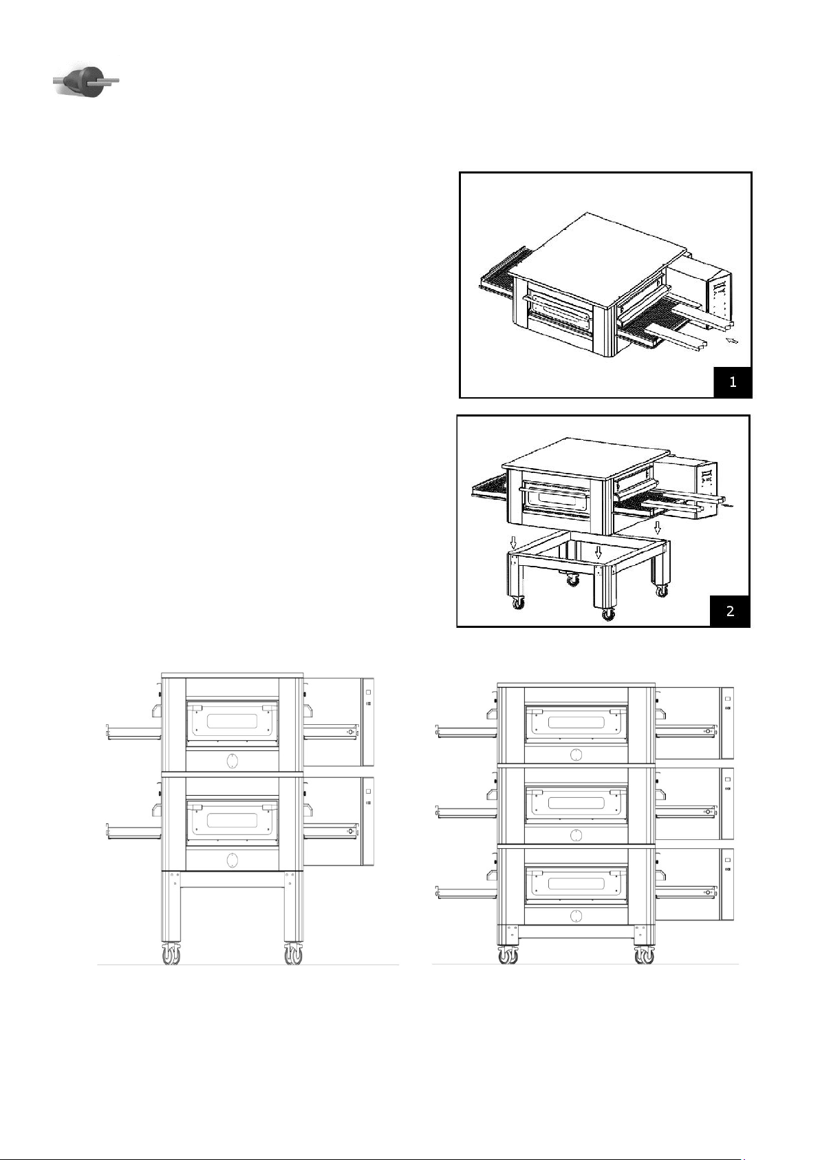
4—INSTALLATION
4.1–INSTRUCTIONS FOR THE USER
The place where the oven is installed must have the following environmental characteristics:
•To be dry, temperature and relative humidity of the room must not be over data stated in tab
3.1;
•Water sources at safe distance;
•Adequate ventilation and lighting corresponding to hygiene and security rules following the
existing laws.
Check that the electrical set-up corresponds with the numbers of the technical sheet Par. 3.1, and
on the small plate at the back of the oven. The characteristics of the electric socket must be
compatible with the plug installed on the cable.
FORESEEN USE: PIZZA BAKING, GRATINATING OF GASTRONOMY
PRODUCTS AND HEATING OF FOODSTUFF IN BAKING PANS.
THE OVEN CAN BE USED EXCLUSIVELY BY AN AUTHORIZED OPERATOR
(USER)
THIS APPLIANCE IS NOT INTENDED FOR USE BY PERSONS (INCLUDING
CHILDREN) WITH REDUCED PHYSICAL, SENSORY OR MENTAL
CAPABILITIES, OR LACK OF EXPERIENCE AND KNOWLEDGE, UNLESS THEY
HAVE BEEN GIVEN SUPERVISION OR INSTRUCTION CONCERNING USE OF
THE APPLIANCE BY A PERSON RESPONSIBLE FOR THEIR SAFETY.
CHILDREN SHOULD BE SUPERVISED TO ENSURE THAT THEY DO NOT PLAY
WITH THE APPLIANCE.
THE OVEN MUST NOT BE INSTELLED IN PROXIMITY OF THE
INFLAMMABLE MATERIALS
(WOODS, PLASTIC, COMBUSTIBLE, GAS ETC.) AVOID THE CONTACT OF
INFLAMMABLE OBJECTS WITH THE HOT SURFACES OF THE OVEN.
ALWAYS ASSURE THE SAFETY FIREPROOF CONDITIONS. MAINTAIN A
FREE SPACE AROUND THE OVEN OF AT LEAST 30 CM

7
4—INSTALLATION
4.2–HANDLING AND POSITIONING
Use a forklift or a trans pallet with suitable capacity lift
the small hoods up.
Wrap the forks with smooth material and insert them
in the cooking chamber (Fig.1).
Place the oven on the stand lean on the edges (Fig.2).
4.3–STACKABLE
OVENS STACKABLE UP TO 3 DECKS

8
4—INSTALLATION
4.4- ELECTRIC CONNECTION
To connect the machine to the electric network it is necessary to proceed as follows:
1) connect to the wires to the terminals L1—L2—L3—N —with unsheathed cable with
ferule tab 3.1.
2) put together the other end of the cable and a plug, which is normalized and polarized (the
distinction between phase and neutral must be unequivocal.
4.5–EQUIPOTENTIAL
The equipment must be connected with an equipotential system. The connection terminal is located
near the terminal box. The bonding wire must have a minimal section of 10 mm ².
THE CONNECTION TO THE MAIN POWER SUPPLY MUST BE
EXCLUSIVELY CARRIED OUT BY AN AUTHORIZED TECHNICIAN
(ELECTRICIAN) ABLE TO SATISFY THE TECHNICAL AND
PROFESSIONAL REQUIREMENTS STATED BY THE REGULATIONS IN
FORCE IN THE COUNTRY OF USE.
THIS TECHNICIAN MUST ISSUE A DECLARATION OF CONFORMITY
FOR
THE INSTALLATION CARRIED OUT.
THE MAIN LINE SHOULD BE EQUIPPED WITH SAFETY DEVICES BY A
DIFFERENTIAL SWITCH / CIRCUIT BRAKER, CO-ORDINATED WITH
THE GENERAL EARTH INSTALLATION, IN CONFORMITY WITH THE
LOCAL AND NATIONAL LAWS
ONCE THE ELECTRIC CONNECTION HAS BEEN PERFORMED, THE AUTHORIZED
TECHNICIAN (ELECTRICIAN) MUST ISSUE A DECLARATION CERTIFYING THE
MEASUREMENT OF THE CONTINUITY OF THE EQUIPOTENTIAL PROTECTION
CIRCUIT.
THE APPLIANCE IS TO BE SUPPLIED THROUGH A RESIDUAL CURRENT
DEVICE (RCD) HAVING A RATED RESIDUAL OPERATING CURRENT NOT
EXCEEDING 30 MA

5- USE AND FUNCTIONING
9
5.1- COMMAND PANEL
Oven switch on - off key
Parameters value decrease key
Programming access key
Parameters value increase key

5- USE AND FUNCTIONING
10
5.2- KEYPAD KEYS/LED MANAGEMENT
The board includes connection to a 4 functions keypad.
The functions the 4 keys should have are indicated in the figure below :
Key Logical switch on/off of the control unit (passage from OFF status to functioning
mode).
Key Decrease function used during the values settings.
Key Access parameter changes (baking time and temperature) and the relevant ENTER
(confirm) button for passage to the next parameter.
Key Increase function during value settings. This key is used to activate the oven net
functioning (on first pressing the motor activates, press again to stop it). During
movement of the net the display shows an indicator in the bottom right hand corner indicating
net movement.
5.3- CONTROL UNIT POWER
When the control unit is switched on, the FW version appears and then the machine positions on the
status on which it was previously switched off (therefore it could be in active net status and with
thermoregulation ON). Any OFF status is signalled by a situation as shown in this image:
The second line only shows if the "AUTOSTART" mode is active and if a valid activation time is present.
EXITING OFF STATUS
To exit the OFF status you need to press the ON/OFF key for 3 seconds.

5- USE AND FUNCTIONING
11
5.4–PRESET
The board is reset by pressing, during switch on, all 4 buttons. Preset is confirmed by signaling it on
the display with: “Preset Complete”.
At this point the board must be switched off and switched back on again.
NB: preset is also possible from the technical menu (see relevant chapter).
5.5- FUNCTIONING DISPLAY MANAGEMENT
•Set point temperature: it is the temperature the system aims for using the pilot of a heating
resistor. The temperature is kept monitored by a probe PT1000.
NB: the set point display of the temperature ends after 3 seconds from its setting. To view it
you need to press the key. Also in this case the display stays on for 3 seconds.
•Baking time: it is the time in which a food product stays inside the oven from the moment in
which it is rested on the net at the start of the tunnel up to its exit.
•“ ” indicates the actual switch on of the heating resistor
•Temperature read by probe Net movement indicator

5- USE AND FUNCTIONING
12
5.6–CHANGING TEMPERATURE AND TIME PARAMETERS
On pressing the key, the relevant symbol for net movement and the baking time are NO
longer visible; instead, the two SET POINT temperatures are displayed for the Top and Bottom probe.
The temperature of the top probe flashes and using the increase and decrease keys you can change
the values from a minimum of 1 degree to a maximum of 320°C.
On pressing the key, the set point value is set of the “Top” probe and the change of set point
parameter is activated on the “Bottom” probe.
On pressing the key, the set point value is set of the “Bottom” probe and the change of
“Baking time” parameter is activated.
In particular, the change takes place according to the following resolution:
From 2 min to 6 minutes 5 seconds resolution
From 6 min to 10 minutes 15 seconds resolution
From 10 min to 20 minutes 30 seconds resolution
From 20 min to 30 minutes 1 minute resolution
Pressing the again, you exit the parameters, going to the functioning display.
NB: changing the two parameters can independently take place both with the net active and in
stoppage mode.
5.7- COOL DOWN
At the time of switch off, two events can occur by pressing the key for 3 seconds.
If the temperature of the oven is under that set, switch off is instantaneous.
If one of the two oven temperatures (TOP or BOTTOM) is over that set on switch off, the control unit
goes to COOL DOWN status.
During this phase the net is active and all the increase and decrease keys are active to allow you to
vary its speed.
Heating is (obviously) deactivated and this phase continues until the temperature goes below the
set point temperature for cool down (NON-modifiable preset value: 140°C).

5- USE AND FUNCTIONING
13
5.8–PROBE ERROR MANAGEMENT
OVER TEMPERATURE
On reaching the over temperature value set in the technical menu, the display indicates the following:
In the second row, the temperature read value is displayed.
The Over Temperature value is NOT settable and is set to 490°C .
PROBE IN OPEN CIRCUIT o SHORT CIRCUIT
If the probe was in “Open” or “Short circuit” status, an error signal is shown on the display.
Once the fault is fixed, to exit the error signal, you need to press the OFF status.
5.9–SCHEDULER FUNCTIONALITY
From the OFF status, press to access the menu in question.
In this menu: (-) decrease, (+) increase, (Enter) select/confirm
The items that appear are as follows:
1. Clock regulation
2. Autostart
2.1 Sunday
2.2 Monday
2.3 Tuesday
2.4 Wednesday
2.5 Thursday
2.6 Friday
2.7 Saturday
3Exit

5- USE AND FUNCTIONING
14
1. To change the current time or minutes, day of the week.
2. To change autostart enabling.
2.1 2.7(Visible if Autostart is enabled) To change the advance switch on time for the day selected.
The range of minutes varies from 00..59 , while the hours range varies from 00,..,23,--. Where --
also inhibits the minutes field and disables the autostart for the day selected.
3. Return in OFF.
>OFF status: Display <
HOUR, in OFF status, the display on the first line shows
0 10 15
|O|F|F| | | | |D|D|D| |H|H|:|M|M|
DDD: Current day of the week . HH:
Current time
MM: Minutes of the current hour
HOUR, in OFF status, the display on the second line shows if autostart is enabled and if there is a
valid next switch on during the week
0 10 15
|S|t|a|r|t|:| |d|d|d| |h|h|:|m|m|
ddd: Autostart day of the week
hh: Autostart hour mm: Autostart
minutes of the hour
>ON status: Autostart functioning <
It was set that after a start due to autostart, the temperatures of the TOP and BOTTOM set point are
set to that of COOLDOWN and the net is moving at 03:00.
5.10–ENTER THE TECHNICAL MENU TO CHANGE PARAMETERS
To enter the technical menu, you need to start with the board off and press the and keys during
switch on.
At this point, enter the technical parameters programming menu.

5- USE AND FUNCTIONING
15
To go from one parameter to another, use the "increase" and "decrease" keys. Settable
parameters:
Language
Preset
Exit
To change one of the parameters, press ENTER and then use the increase/decrease keys. To exit the
technical menu, move up to EXIT and press ENTER.
Description of parameters.
Language
You can change the user interface language, options available ENGLISH, ITALIAN, GERMAN, SPANISH
and FRENCH.
Preset
Pressing the enter key for 4 seconds on this parameter, you preset the board and the following writing
is indicated:
EXIT: exit technical menu

5- USE AND FUNCTIONING
16
5.11–PRODUCTIVITY
Cooking time and coking temperature are extremely variables. They depend on several variables and
they can not be stated by the manufactures of the oven. Here after some suggestions for user’s
reference only.
7485.0150
Pizza Diameter
Productivity: average per hour *
25
cm
30
pz/h
32
cm
15
pz/h
40
cm
13
pz/h
*valves indicative only
7485.0155
Pizza Diameter
Productivity: average per hour *
25
cm
90
pz/h
32
cm
30
pz/h
40
cm
26
pz/h
45
cm
12
pz/h
*valves indicative only
7485.0160
Pizza Diameter
Productivity: average per hour
*
25
cm
165
pz/h
32
cm
75
pz/h
40
cm
39
pz/h
45
cm
24
pz/h
*valves indicative only
7485.0165
Pizza Diameter
Productivity: average per hour
*
25
cm
180
pz/h
32
cm
105
pz/h
40
cm
52
pz/h
45
cm
36
pz/h
*valves indicative only

17
6–MAINTENANCE
6.1–CLEANING
Cleaning must be carried out daily in compliance with hyenic and sanitary rules in force.
Cleaning of chamber:
Disconnect the oven from the main power by switching off the main switch;
Remove the drawers below the belt;
Remove the casing coupling network from its housing and release it by moving it upwards;
Rotate manually the belt until the pivot shaft drop network finds himself at the engraving of the
coupling network;
Lift the small hoods up;
Lift the belt both sides and slide it from control side;
Open the side door and remove the panels with hides paying attention to the hot surface;
Clean the metal surfaces with a sponge steeped in water or non-abrasive –corrosive detergents then
rinse the surfaces with a damp sponge.
External clearing of the oven: (surfaces in stainless steel, inspection glass and control panel):
this operation has to be performed with cold oven.
For any intervention of supplementary maintenance, repairing and/or replacement refer exclusively
to the authorized dealer where the oven has been purchased and/or to an authorized technician
satisfying the technical and professional requirements stated by the regulations in force.
7–DISPOSAL
7.1- GENERAL WARNINGS
When dismantling the oven, compulsorily observe the provisions of the regulations in force.
Differentiate the parts making up the oven according to different types of construction materials
(plastic, copper, iron, etc.).
BEFORE PERFORMING ANY TYPE OF MAINTENANCE INTERVENTION, IT IS
COMPULSORY TO DISCONNECT THE PLUG OF THE OVEN FROM THE POWER
SUPPLY OUTLET.
IT IS RECOMMENDED TO USE PROPER GLOVES AND SUITABLE
CLOTHING TO AVOID BURNINGS.
IT IS FORBIDDEN TO USE THROWS OR DRIPS OF WATER, ABRASIVE OR
CORROSIVE SUBSTANCES, AND ANYTHING ELSE THAT CAN DAMAGE
THE COMPONENTS, COMPROMISE THE SAFETY, AND BE DANGEROUS
FROM AN HYGIENIC POINT OF VIEW.

18
8—SPARE PARTS
8.1—SPARE PARTS OVENS
Components list
DESCRIPTION
7485.0150
7485.0155
7485.0160
7485.0165
6
Tempered glass
5V010032
5V010031
5V010031
5V010033
11
Hood adjustment knob
5P100052
5P100052
5P100052
5P100052
15
Lower heating element
5R050482
5R050491
5R050490
5R050493
16
Upper heating element
5R050483
5R050481
5R050480
5R050493
18
Heatsink fan
5V050001
5V050001
5V050001
5V050001
19
Heatsink fan coverage
5P100300
5P100300
5P100300
5P100300
27
Control panel label
5E200710
5E200705
5E200700
5E200715
28
Display
5I100120
5I100120
5I100120
5I100120
29
Keypad
5P010300
5P010300
5P010300
5P010300
30
Cooking machine card
5S010068
5S010068
5S010068
5S010068
31
Switching power supply
5A010100
5A010100
5A010100
5A010100
32
Interface card
5S010058
5S010058
5S010058
5S010058
33
Solid state relay
5R020120
5R020121
5R020122
5R020123
34
Relè 24V-240V
5R020101
5R020101
5R020101
5R020101
35
Circuit brakers board
5T010331
5T010331
5T010331
5T010331
36
Terminals
5M100113/14
/15
5M100113/14
/15
5M100113/14 /15
5M100113/14 /15
37
Security thermostat
5T010016
5T010016
5T010016
5T010016
38
Motor reduction
5M010100
5M010100
5M010100
5M010100

19
8
—
SPARE
PARTS
8.2
–
EXPLODED
VIEW
:

20
9-ELECTRIC EQUIPMENT
9.1–WIRING DIAGRAMS TUNNEL 7485.0150 & 7485.0155
HEATING ELEMENTS
TOP
BOTTOM
7485.0150
N°2 1500W
N°2 2200W
7485.0155
N°2 2800W
N°2 4100W
This manual suits for next models
5
Table of contents
Other CombiSteel Oven manuals