3 ComCo Systems Inc. | 800.533.3794 | www.comcosystems.com 500648 Rev. A
Series
System Features
The Model 621 is an overhead pressure/vacuum system that utilizes 6” tubes and
carriers. The carrier travels from the teller unit to the customer unit under pressure and
returns under vacuum. The blower unit is located near the teller unit.
•The Model 621 is configured with three major subsystems:
1. 621 Operator Unit P/N: 201314
2. Dual Blower Unit P/N: 200281-3
3. 621 Customer Unit P/N: 201315
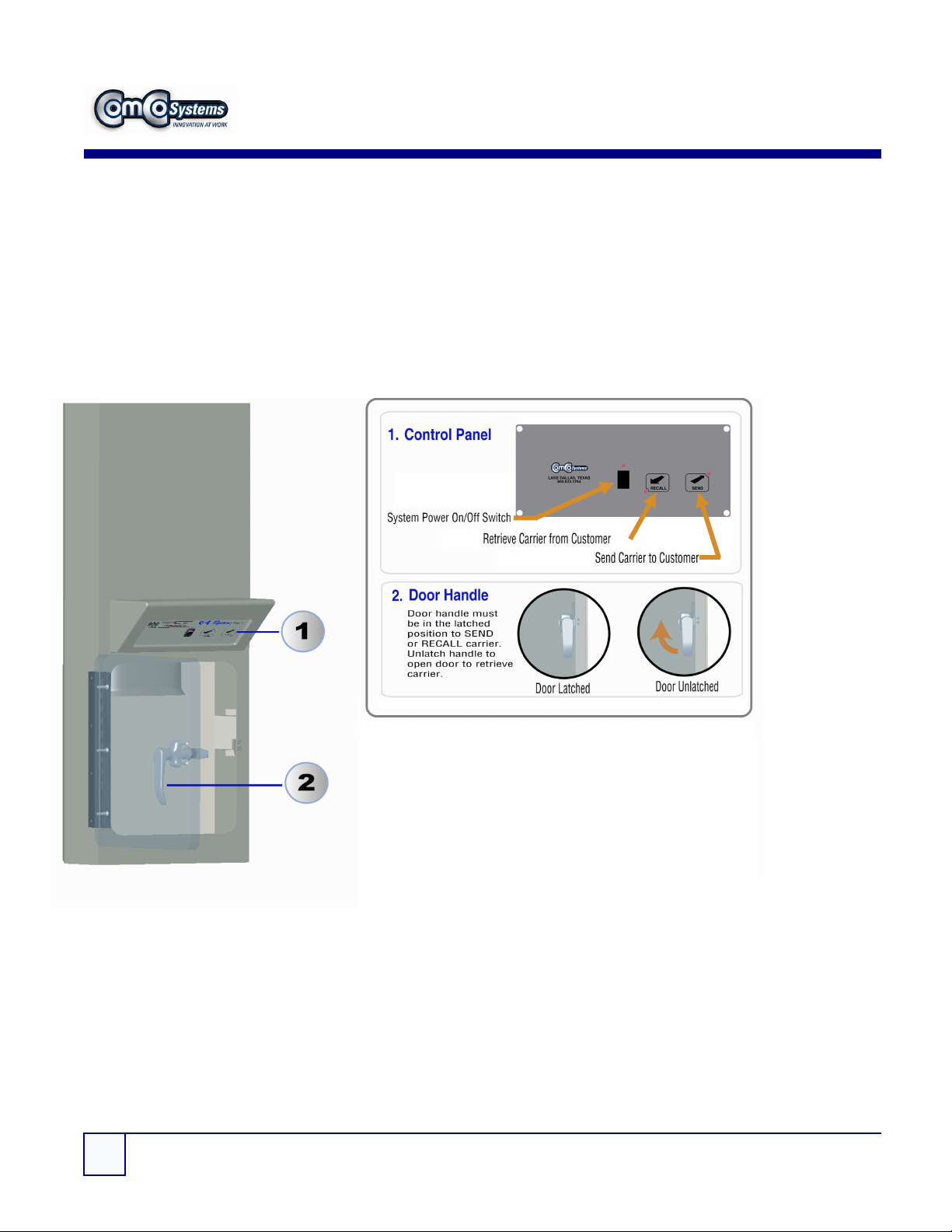
TU-621-201314
Manual operated door unit,
which is suspended from the
ceiling, typically over
countertop.
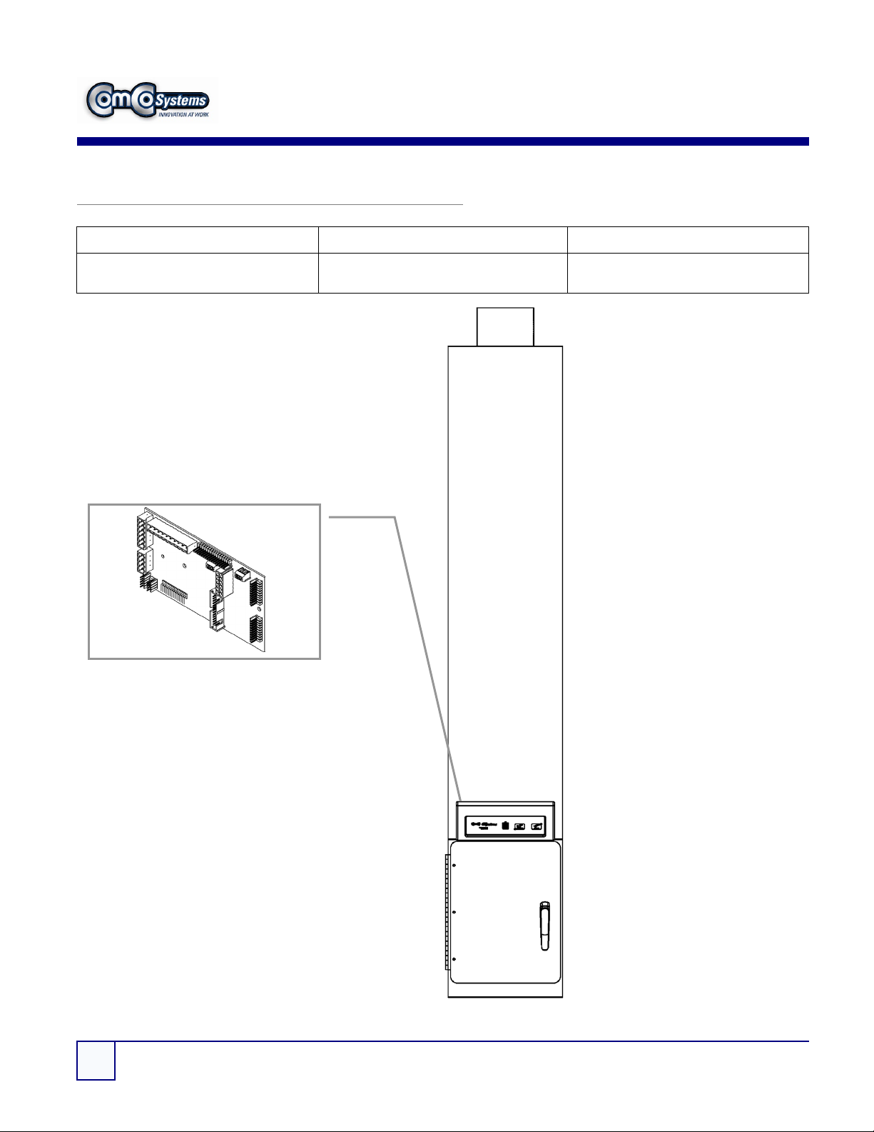
CU-621-201315
Open carrier access design
with optional 2-way video
Blowers
200217-2(x2)
Features:
2 Power Cords
2 115Vac/15A
2 Blowers for pressure
2 Blowers for vacuum