ATE-ANPL-ANPA
Fan Installation, Operation &
Maintenance
This document contains information on proper storage, installation, operation and general maintenance of Comefri
USA fans ATE, ANPL, ANPA. Failure to comply with proper installation procedures may void the warranty. The
technical data and the permissible limits of the fan are clearly listed on the fan plate. All fans are balanced and
tested before leaving the factory.
All Comefri USA Fans are manufactured according to our Quality Management System, in conformity with ISO
9001:2000. Comefri USA Quality System is certified by BSI.
Receiving and Handling
Each fan is carefully checked before shipment. When receiving a fan it is necessary to verify that it has not been
damaged during transit, especially the rotating parts and any electric part (Motor). In case of damage, immediately
document the damage on the delivery notes and contact the delivery company. Comefri will not take any
responsibility for the transport and the handling of the fan at the customer's premises. The handling of the fan
requires adequate care. Lifting tools according to the weight and packaging of the fan should be used. When
moving the fan with crane, four lifting points have to be provided.
Special care must be taken to ensure that the fan will never be lifted by the shaft ends, motor lifting lug, bearing
supports and/or inlet or outlet flanges. Fixing points of the fans are the base frame, housing frames or lifting eyes if
available.
Note: Any improper handling, even though it may not visually damage the fan, often produces a need to re-balance
the impeller.
Storage
Adequate storage must be provided to protect the fan from dirt and moisture. Do not use plastic sheets, as they will
promote condensation and rust especially in hot and humid environments. Indoor storage is recommended. Store in
a dry, clean area. Storage temperature should range between -4 °F and +113 °F.
Vibration Isolation Base
High vibrations can cause mechanical and structural failure. Bases must have sufficient rigidity to prevent the
generation of vibrations and resonances while supporting the fan and motor. Isolators are used to reduce
and prevent vibrations and noises from being transferred to the surrounding structure. When properly selected the
isolators will attenuate the vibration forces transmitted to the surrounding structure by approximately 90%.
Fan Foundations
Many fan problems are caused by a poorly designed foundation. The foundation must be strong enough to hold the
weight of the fan, motor, isolation base plus the loads created by its running. The natural frequency of the
foundation should be at least twice the natural frequency of the base isolators.
Installation 0 INSTALLATIONS
Installation is only to be carried out by trained personnel in observance of these operating instructions. The fans
must be firmly fixed on isolation base frames. The fixing must be made avoiding any stress or deformation of the
supporting structure.
Duct Connections
It is important to design proper ducting. Poor ducting can affect the fan performances reducing the volume flow and
pressure and increasing the system noise.
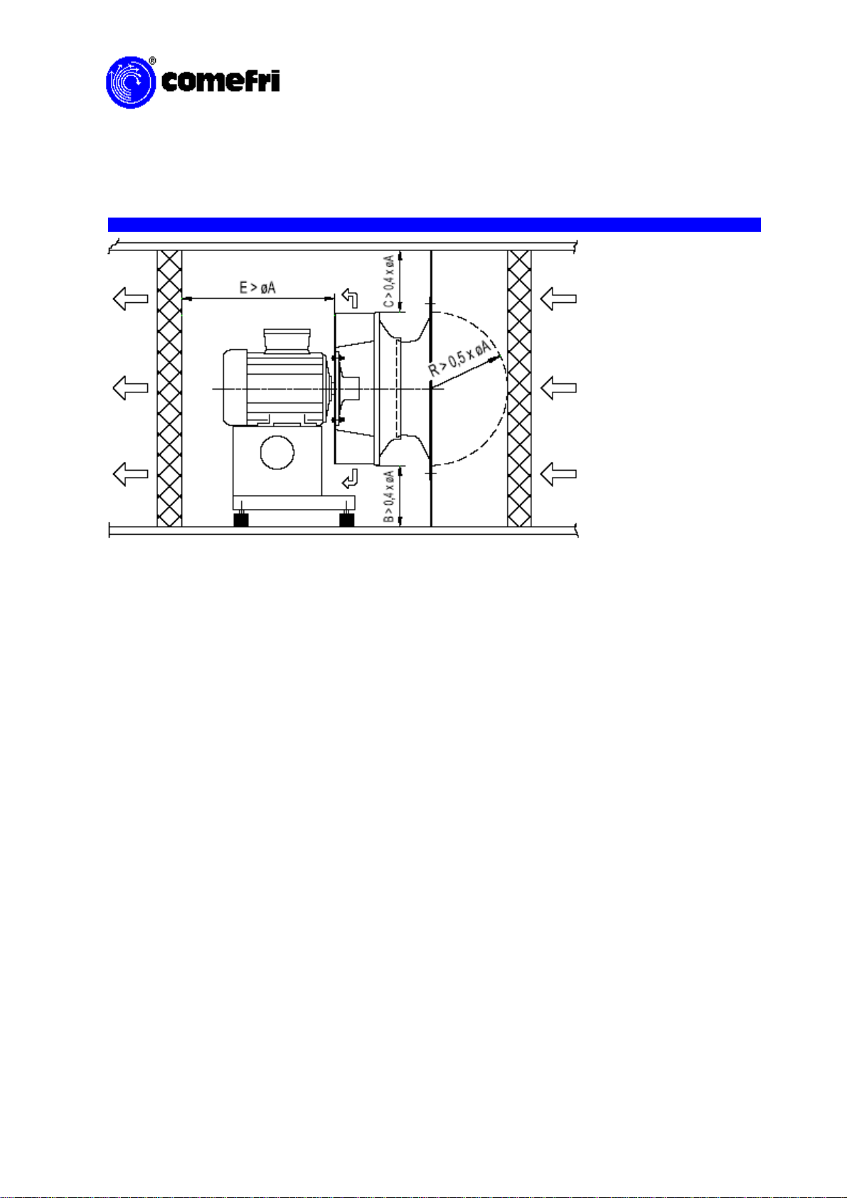
Inlet Connections
Inlet spin is caused by improper ducting on the inlet of the fan and will result in a reduction in fan
performance. The change in performance is directly related to the amount of the spin. Installing elbows or duct
turns too close to the fan inlet will also affect the fan performance. If the elbow is too close to the fan inlet, the air
will flow uneven into the fan. Allowing at least one wheel diameter from the elbow to the fan inlet will produce a
uniform inlet flow distribution. In installations where the inlet is un-ducted, there should be a least half wheel
diameter of free space on the inlet side, as shown in figure 1.