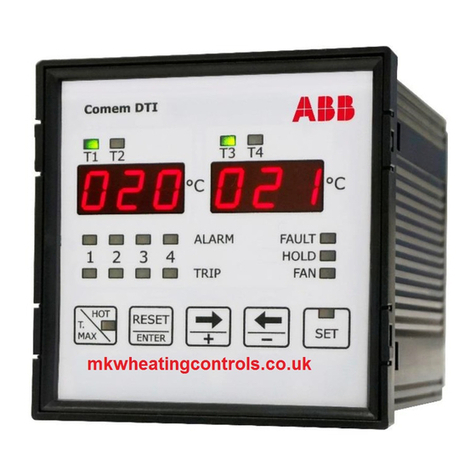
COMEM DTI User manual

Temperature monitoring unit
DTI and eDTI
Instruction manual
TRANSFORMER COMPONENTS

TEMPERATURE MONITORING UNIT DTI AND EDTI
2
Content index
Safety .................................................4
DTI and eDTI .......................................5
Electrical diagram...............................7
Front panel description.......................8
Programming of the device ................9
Modality of tripping and restore .......15
Diagnostic ........................................16
Visualization of the maximum
measured temperature .....................17
Visualization of the channels with
the higher temperature.....................17
Test of the light signaling .................17
Exclusion of the input probes
not used............................................17
Technical features............................18
Movement, transport and storage ....18
Appendix A: MODBUS address.........19
Dimensions.......................................20

3
Safety
Safety instructions
Make sure that any person installing, taking into operation and operating the
“temperature monitoring unit DTI/eDTI”:
• is technically qualied and competent.
• fully comply with these assembling instructions.
Improper operations or misuse could cause danger to:
• life and limb
• to the equipment and other assets of the operator
• to the equipment proper function
Opening of the device will void your warranty.
Safety instructions in this manual are shown in three different forms to emphasi-
ze important information.
This information indicates particular
danger to life and health. Disregarding such
a warning can lead to serious or fatal injury.
This information indicates particular
danger to equipment or other property of
the user. Serious or fatal injury cannot be
excluded.
The temperature control unit DTI/eDTI
must not be installed near sources of
electromagnetic interference.
Installation, electrical connection and
fitting the device may only be carried out by
qualified personnel and only in accordance
to this instruction manual.
It is responsibility of the user to make
sure that the device is used for specified
application only.
For safety matters, please avoid any
unauthorized and improperly works.
All relevant fire protection regulation must
be strictly observed.
These notes give important or specific
information concerning the equipment or
as to work with the equipment.
WARNING CAUTION
CAUTION
CAUTION
WARNING
NOTE

TEMPERATURE MONITORING UNIT DTI AND EDTI
4
DTI and eDTI
Product description
The Temperature monitoring device DTI/eDTI is used in resin or dry type transfor-
mers and can also be easily adapted for use in oil transformers.
The DTI/eDTI uses PT100 temperature probes for a constant monitoring of tran-
sformer temperatures. The device generates two intervention levels of electric
signals (alarm and trip).
Safety notes on the equipment operation
The electrical installation must conform to the national safety regulations.
The Temperature monitoring device DTI/eDTI has double insulation. Earthing is
not required.
The DTI family are devices which use PT100 temperature probes for constant
monitoring of transformer temperatures in 4 points: three on the transformer
winding columns and one on the machine’s magnetic circuit.
If the transformer malfunctions, causing its temperature to rise, DTI unit genera-
tes an alarm signal. If the temperature reaches danger levels the unit generates a
second intervention level. Moreover, a switch can manage the fan.
Installation
The device must be installed and used by personal opportunely learned.
Before to proceed at the installation it’s necessary to verify if the device is intact
and it hasn’t damages due to transportation or handling. The power supply must
be compatible with the device range. The instrument installation must be done in
total absence of voltage and observing the security norm in force.
All operation of maintenance and reparation executed by not authorized persons
are forbidden.
If during the functioning the device becomes unsafe, it’s necessary to put it out of
action and to be sure that this device won’t be used unintentionally.
The use shall be considered unsafe when the instrument:
• doesn’t work regularly
• has damage clearly visible
• has damage caused of transport or handling
• is stored in bad condition
The wires must be fixed properly
CAUTION

5
DTI and eDTI
Connection of the temperature sensors
For the connection of the sensor RTD PT100 it’s necessary to follow the indica-
tion of the wiring diagram of this manual: pay attention to not invert the position
between the conductors with red insulator and the conductor with white insulator.
The probes type PT100 with three wires use the third wire to compensate the
resistance of the conductors (max 20 Ω).
If the sensor has two wires (normally white and red) it’s necessary to short-circuit
the terminals with the red wire (1-2, 4-5, 7-8, 10-11).
To reduce the external noises, it’s necessary to use the following indication for
the wires:
• use probes with shielded wire connected at earth and wires twisted
• separate the wires of the probes from wires of power supply
• use wires with section at least of 0,5 mm2
• use wires with conductor with tin or silver-plated
Output relays
For the connection of the output contacts it’s necessary to follow the indication
in the diagram.
The ALARM and TRIP relays commute when the threshold set value gets over.
The FAULT relay is normally energized, and it commutes in presence of a PT100
anomaly or of the device.
During the normal functioning of the device the contact 38-39 is open, while the
39-40 is closed.
The FAN relay is used to control the cooler fan, according to the on/off thresholds
set.

TEMPERATURE MONITORING UNIT DTI AND EDTI
6
Electrical diagram
View rear panel of the instrument with terminals for the connections

7
°C
T3 T4
123 4
FAULT
HOLD
FAN
SET
ALARM
TRIP
T1 T2
HOT
T.
MAX ENTER
RESET
°C
eDTI
Modbus RTU / 4-20mA
°C
T3 T4
123 4
FAULT
HOLD
FAN
SET
ALARM
TRIP
T1 T2
HOT
T.
MAX ENTER
RESET
°C
DTI
°C
T3 T4
123 4
FAULT
HOLD
FAN
SET
ALARM
TRIP
T1 T2
HOT
T.
MAX ENTER
RESET
°C
DTI
033048
°C
T3 T4
123 4
FAULT
HOLD
FAN
SET
ALARM
TRIP
T1 T2
HOT
T.
MAX ENTER
RESET
°C
eDTI
Modbus RTU / 4-20mA
033048
Front panel description
1
2
3
4
8
9 10 10
11
7
6
5
Legend:
1. LEDs T1-T2-T3-T4 for the on-measuring channel displayed
2. T1-T2 and T3-T4 displays for the channel temperature visualization and
settings
3. LEDs ALARM for the Alarm status in the related channels (1 to 4)
4. LEDs TRIP for the Trip status in the related channels (1 to 4)
5. LED FAULT: failure indication (device or PT100 probes)
6. LED HOLD: the manual reset is active
7. LED FAN: the ventilation output is active
8. Push - button HOT / T. MAX to display the measured channel with higher
temperature (LED indication activated) and to display maximum
temperatures achieved
9. Push - button ENTER / RESET to conrm programming set and the manual
alarm reset intervention
10. Push - buttons →+ / ←-for selecting the displayed channel and for changing
parameter of programming
11. Push - button SET for the settings

TEMPERATURE MONITORING UNIT DTI AND EDTI
8
Programming of the device
When the device is switched on, on the display will ash the index of the internal
software: later the device starts to display the temperature read on the measured
input.
To enter in the programming mode, press the button SET for some second up to
light the relative SET LED.
The settings appear in the sequence showed after. To go out of the programming
mode without changing the preset values, it’s necessary to press SET without
conrming with the ENTER key the modied data.
To modify the values or the status, it’s necessary to use →and ←keys and the
ENTER key to store the modication.
The pressure of the ENTER key move automatically the programming at the
successive function or value.
Selection of the HOLD function
This is the rst function in the set menu. In this programming phase the HOLD
LED switches on.
The Hold function allows to store the alarm condition that can be rearmed only
manually with the RESET button when the temperature is lower than the threshold
set.
If this function is disabled it’s possible to rearm the ALARM with the RESET
button even if the temperature is higher than the threshold set, while the value of
temperature come back under the threshold set the alarm will be automatically
deleted.
To set the Hold function it’s necessary to use the ←and →keys:
ON function enabled
OFF function disabled
Press the ENTER key to conrm the operation.
HOLD mode T1-T2 display T3-T4 display
HOLD mode deactivated HLD Off

9
Selection of the number of active inputs
It is possible to select the number of activated inputs. It’s possible to choose
between 3 and 4 inputs enabled; if there are 3 inputs enabled the T4 display
remain off.
Select 3 or 4 inputs with ←and → keys.
Conrm with ENTER.
Control ventilation
The FAN led will switch on indicating the programming of the ventilation control.
If 3 inputs are selected the following setting are available:
• ventilation control inhibited
• fan control active on 3 inputs
Select the conguration with ←and → keys.
Conrm with ENTER.
If 4 inputs are selected the following setting are available:
• ventilation control inhibited
• fan control active on 3 inputs
• control active only on fourth input
Select the conguration with ←and → keys.
Conrm with ENTER.
Programming of the device
Active inputs mode T1-T2 display T3-T4 display
HOLD mode deactivated Ch 123
All inputs activated Ch ALL
Fan mode (3 inputs) T1-T2 display T3-T4 display
Fan control inhibited FAN Off
Fan control on 3 inputs FAN ON
Fan mode (3 inputs) T1-T2 display T3-T4 display
Fan control inhibited FAN Off
Fan control on 3 inputs FAN ON
Fan control on 4 inputs FAN 4

TEMPERATURE MONITORING UNIT DTI AND EDTI
10
Programming of the device
Selection of the threshold of switch-on and switch-off ventilation
It is possible to program the threshold for enabling and disabling the ventilation.
• Selection the threshold for disabling ventilation
The FAN LED is on, with xed light indicates this phase of programming.
With ←and → keys select the value of temperature indicated on display.
Interval of programming: from -25°C up to (enabling threshold -1°C)
Conrm with ENTER.
• Selection the threshold for enabling ventilation
The FAN LED is on, with ashing light indicates this phase of programming.
With ←and → keys select the value of temperature indicated on display.
Interval of programming: from (disabling threshold +1°C) up to 200°C
Conrm with ENTER.
Selection of the alarm and trip threshold
The FAN This setting starts to program from the channel number 1.
The ALARM LED ON indicates the programming of the alarm:
With ←and →keys select the value of temperature
Interval of programming: from -25°C up to (trip threshold -1°C)
Conrm with ENTER.
The TRIP LED ON indicates the programming phase of the tripping threshold.
With ←and →keys select the value of temperature
Interval of programming: from (alarm threshold +1°C) up to 200°C.
Conrm with ENTER.
Repeat the same operation for the successive channels.
Selection of address network identication for the communication of the serial
port (MODBUS-RTU protocol)
This setting is indicated on displays with:
• value to set on T1-T2 display
• ID on T3-T4 display.
With ←and →keys select the number choice
The range for accepted value is from 1 to 247.
Conrm with ENTER.
This setting is significant only for eDTI model.
NOTE
Modbus setting T1-T2 display T3-T4 display
Setting address MODBUS network 001 ID

11
Selection of the baud rate
This setting is indicated on displays with:
• BDR on T1-T2 display
• value to set on T3-T4 display.
With ←and →keys select the baud rate
It’s possible to choose between the following values: 2,4 - 4,8 - 9,6 - 19,2 kbps.
Conrm with ENTER.
Selection data bit and stop bit
This setting is indicated on displays with:
• the type of parity on T1-T2 display
• the number of data bit and stop bit on T3-T4 display.
With ←and → keys select the options.
Conrm with ENTER.
Programming of the device
This setting is significant only for eDTI model.
NOTE
NOTE
Data-stop bit setting T1-T2 display T3-T4 display
No parity / 8 data bit - 1 stop bit NO 8-1
No parity / 8 data bit - 2 stop bit NO 8-2
Even parity / 8 data bit - 1 stop bit EVE 8-1
Odd parity / 8 data bit - 1 stop bit ODD 8-1
Baud rate setting T1-T2 display T3-T4 display
Baud rate: 19200 BDR 19.2
Baud rate: 9600 BDR 9.6
Baud rate: 4800 BDR 4.8
Baud rate: 2400 BDR 2.4

TEMPERATURE MONITORING UNIT DTI AND EDTI
12
Selection of the linked channel with the analogue output
This setting is indicated on displays with:
• AN on T1-T2 display
• the linked measure channel on T3-T4 display: CH 1/2/3/4 for the 1/2/3/4
measure channel, ALL to link the measure channel with the higher temperature.
With ←and → keys to select the options.
Conrm with ENTER.
Conguration output signal
In this phase it’s possible to dene the type of signal of analogue output as 0-20
mA or 4-20 mA.
This setting is indicated on displays with:
AN0 -20 to set the output as 0-20mA or (0 mA = -30°C; 20 mA = 200°C)
AN4 -20 to set the output as 4-20 mA or (4 mA = -30°C; 20 mA = 200°C)
With ←and → keys select the options.
Conrm with ENTER.
Programming of the device
This setting is significant only for eDTI model.
The maximum load for analogue output
is 400 Ω.
NOTE
NOTE NOTE
Link channel setting T1-T2 display T3-T4 display
Channel with higher temperature AN ALL
Measure channel CH 1 AN Ch 1
Measure channel CH 2 AN Ch 2
Measure channel CH 3 AN Ch 3
Measure channel CH 4 AN Ch 4
4-20 signal setting T1-T2 display T3-T4 display
Output proportional 0 - 20 mA AN 0 -20
Output proportional 4 - 20 mA AN 4 -20
Measure channel CH 2 AN Ch 2
Measure channel CH 3 AN Ch 3
Measure channel CH 4 AN Ch 4

13
Programming of the device
Conguration diagnostic probes
This function allows to enable or to disable the control on the probes. This fun-
ctionality controls the variation of the temperature in a dened time. A ag raise
if this variation is higher than a set value.
Exit from the programming phase
Press the SET key or wait for about 8 seconds without to press any key to come
out of the programming phase.
It’s necessary to indicate the maximum variation temperature:
• FDC: min 5°C or max 30°C
and after the time in which to do the control:
• FDC: min 10” or max 90” (time in seconds)
The →+ key is used to increase the values while the ←- key to decrease.
Conrm with ENTER.
FDC setting T1-T2 display T3-T4 display
FDC mode disabled FDC Off
FDC mode enabled FDC ON
Temperature conguration FDC T1-T2 display T3-T4 display
Min °C FDC -5°
Max °C FDC 30°
Time conguration FDC T1-T2 display T3-T4 display
Min in seconds FDC 10’’
Max in seconds FDC 90’’

TEMPERATURE MONITORING UNIT DTI AND EDTI
14
Modality of tripping and restore
Alarm
On the relative channel, if the threshold value set is exceeded of +1°C, after 5
seconds the ALARM relay is energized and the ALARM led is.
The alarm rearm (relay de-energized and the involved LED off) occurs when the
temperature goes down of 2°C respect at the threshold value set.
Trip
On the relative channel, if the threshold value set is exceeded of +1°, after 5
seconds the TRIP relay is energized and the TRIP led is.
The trip rearm (relay de-energized and the involved LED off) occurs when the
temperature goes down of 2°C respect at the threshold value set.
To silence alarm
If the Hold function is disabled, it’s possible to silence the alarm condition. During
the alarm condition the ALARM relay and the “ALARM” optical signalling are
enabled.
Pressing the Reset button, the relay will be de-energized while the optical signal-
ling of the alarm condition becomes ash.
If the temperature increases up to reach the (TRIP temperature - 1°C), the relay
and the optical signalling are enabled another time.
If after the reset, the temperature goes down under the threshold value set, the
ashing optical signalling will be automatically deleted.

15
Diagnostic
The device is provided of the thermic probes diagnostic function.
The condition controlled on the measured input are:
• Probe PT100 interrupted: signalling on the display the message O P E (open).
• Probe in short circuit: signalling on the display the message S H R
(short circuit).
• Probe out of order for wrong read temperature: signalling on the display the
message F D C.
When the device switches on the auto-diagnostic, FAULT relay commutes and
it remains in the energized status until one of the above-described conditions
appears, or if a device failure occurs, or if the power supply is absent.
The anomaly conditions are signalled also by the FAULT led on.
Every time that a probe is out of order because it is interrupted (OPE) or in short
circuit (SHR) or the delta of temperature is too elevated (FDC), the corresponding
channel LED ashes until the anomaly stop.
The alarm of interrupted probe (SHR) or open probe (OPE) will be reset automa-
tically while the alarm for the delta of temperature (FDC) disappears by pressing
this sequence:
• push the ENTER key
• keep it pressed
• press the →+ key at least for 5 seconds.
The status of the relay contact (all available with exchange contact) is showed in
the following table:
RELAY DISABLE STATUS ENABLE STATUS UNPOWERED STATUS
ALARM OFF: closed 29-30 ON: closed 29-31 closed 29-30
TRIP OFF: closed 32-33 ON: closed 32-33 closed 32-33
FAN OFF: closed 35-36 ON: closed 35-37 closed 35-36
FA U LT OFF: closed 38-40 ON: closed 38-39 closed 38-39

TEMPERATURE MONITORING UNIT DTI AND EDTI
16
Visualization of the channels with the higher temperature
Test of the light signaling
Exclusion of the input probes not used
Visualization of the maximum measured temperature
Pressing the HOT key for some seconds till switching to the HOT led.
On the T1-T2 display, the hotter temperature among the inputs 1 and 2 will
appear.
On the T3-T4 display, the hotter temperature among the inputs 3 and 4 will
appear.
To come back in the standard visualization mode, press the HOT key for some
second up to switch-off the relative signalling led.
Press at the same time←and → keys: all the signalling lights will start to ash
for some seconds.
If one or more inputs are not used, it’s necessary to connect a resistance of value
included between 100 and 200 Ω, or 0.25W.
The input 4 can be disables through the “Selection number of active inputs” on
page 5.
In the gure is showed the connection to disable the input Ch1.
The same connection can be used for the other inputs.
On the relative channel, if the threshold value set is exceeded of +1°C, after 5 se-
conds the ALARM relay is energized and the ALARM led is. The alarm rearm (relay
de-energized and the involved LED off) occurs when the temperature goes down
of 2°C respect at the threshold value set.
01 02 03
R
Ch1
R = 100 120 Ω
0.25W

17
Technical features
Modality of tripping and restore
Auxiliary power supply 24/230 V dc/ac ±15% 50-60 Hz
Maximum consumption 4 VA
Measured inputs 3 - 4 inputs by RTD PT100 (max wire resistance 20 Ω)
Interval of measure -30°C up to +200°C / precision ± 2°C
Interval of visualization -30°C up to +220°C
Tripped delay-hysteresis 5 seconds – 2°C
Measured visualization 2 displays with led 7 segments, 3-digits
Outputs DTI: 4 relay NO-C-NC (250 V 5 A resistive load)
eDTI: 4 relay NO-C-NC (250 V 5 A resistive load),
0-20 mA or 4-20 mA (Default); Modbus RTU
Output functions alarm, trip, fan, auto-diagnostic
programmable functions ALARM, TRIP, HOLD, FAN, T.MAX, HOT, FDC
Connection Extractible terminal with screws, section wires max 2.5 mm2
Insulation 2500 Vrms 50 Hz per 60 s :U aux - input PT100 /
U aux - relay outputs / inputs PT100 - relay outputs
Protection degree IP52 front panel, IP20 rear panel, as CEI-EN 60529
Dimensions - enclosure Flash mounting DIN 96x96 mm, depth 120 mm /
Enclosure thermoplastic self-extinguishing as UL94 V0
Working temperature -10°C up to +60°C, humidity max 95%
Storing temperature -25°C up to +70°C
Standards Security: EN 61010-1
EMC: EN 61000-4-2; EN 61000-4-3; EN 61000-4-4;
EN 61000-4-5; EN 61000-4-11; EN 61000-6-4
The DTI/eDTI temperature monitoring devices are shipped inside a cardboard box
to facilitate transport and storage. As soon as the temperature monitoring device
DTI is received, the customer must perform the following operations:
• examine the outer packaging surface to be sure that it is intact
• check that there are no breakages
If damage is found, please contact COMEM and provide the shipping data
together with the serial number of the unit.
The temperature monitoring device DTI/eDTI must be stored in a dry place at
temperatures as indicated above.

TEMPERATURE MONITORING UNIT DTI AND EDTI
18
Appendix A: MODBUS Address
Register address Operations Description Notes
Operation for monitoring
0x280 R CH1 Instantaneous Temperature [°C]
0x281 R CH2 Instantaneous Temperature [°C]
0x282 R CH3 Instantaneous Temperature [°C]
0x283 R CH4 Instantaneous Temperature [°C]
0x288 R CH1 Maximum Temperature [°C]
0x289 R CH2 Maximum Temperature [°C]
0x28A R CH3 Maximum Temperature [°C]
0x28B R CH4 Maximum Temperature [°C]
0x290 R CH1 Diagnostic 0x0000 Input is right
connected
0x0001 Input is shorted
0x0002 Input is open
0x0003 Input is failure
0x291 R CH2 Diagnostic
0x292 R CH3 Diagnostic
0x293 R CH4 Diagnostic
0x258 R CH1 Instantaneous Temperature &
Diagnostic [°C]
0x0000 Inputis shorted
0x0001 Input is open
Real Value= Read Value (dec) - 25
0x259 R CH2 Instantaneous Temperature &
Diagnostic [°C]
0x25A R CH3 Instantaneous Temperature &
Diagnostic [°C]
0x25B R CH4 Instantaneous Temperature &
Diagnostic [°C]
Operation for controlling
0x300 R / W CH1 Alarm Setting [°C]
0x301 R / W CH2 Alarm Setting [°C]
0x302 R / W CH3 Alarm Setting [°C]
0x303 R / W CH4 Alarm Setting [°C]
0x310 R / W CH1 Trip Setting [°C]
0x311 R / W CH2 Trip Setting [°C]
0x312 R / W CH3 Trip Setting [°C]
0x313 R / W CH4 Trip Setting [°C]
0x272 R / W Fan OFF Temperature Setting [°C]
0x273 R / W Fan ON Temperature Setting [°C]
0x27F W Reset Maximum Temperature Write 0xA55A to reset
Unsigned int

19
Dimensions
°C
T3 T4
123 4
FAULT
HOLD
FAN
SET
ALARM
TRIP
T1 T2
HOT
T.
MAX ENTER
RESET
°C
eDTI
Modbus RTU / 4-20mA
°C
T3 T4
123 4
FAULT
HOLD
FAN
SET
ALARM
TRIP
T1 T2
HOT
T.
MAX ENTER
RESET
°C
DTI
°C
T3 T4
123 4
FAULT
HOLD
FAN
SET
ALARM
TRIP
T1 T2
HOT
T.
MAX ENTER
RESET
°C
DTI
033048
°C
T3 T4
123 4
FAULT
HOLD
FAN
SET
ALARM
TRIP
T1 T2
HOT
T.
MAX ENTER
RESET
°C
eDTI
Modbus RTU / 4-20mA
033048

COMEM SpA
Localita’ Signolo 22, Sr11
36054 Montebello Vicentino
Vicenza - Italy
Tel +39 0444 449 311
www.comem.com
The data and illustrations are not binding. We reserve the right to modify the con-
tents of this document without prior notice following the technical and product
developments.
This installation manual contains essential information for the user required to
install & operate the product. In case you need any further information, contact us
Copyright 2021 COMEM. All rights reserved
Manual-05-2021
Other manuals for DTI
1
This manual suits for next models
1
Table of contents
Other COMEM Measuring Instrument manuals
Popular Measuring Instrument manuals by other brands

Dytran
Dytran 3224C operating guide

Keithley
Keithley 2461 quick start guide

TA Instruments
TA Instruments TGA 2050 Operator's manual

Tractel
Tractel dynafor Pro 1 Installation, operating and maintenance manual

Chauvin Arnoux
Chauvin Arnoux PSD 21 user manual

Y?lmaz So?utma
Y?lmaz So?utma COOL-US CU-935A user manual