Comeval TORAFLEX S10 Installation guide

IOM - RUBBER JOINTS, TORAFLEX® S10/S15/S20/S30/S32
©COMEVAL VALVE SYSTEMS Technical Dept. Ref. IOM - RUBBER JOINTS, TORAFLEX® S10/S15/S20/S30/S32 - Ed.16/07
Comeval Valve Systems reserves the right to alter any technical data contained in this Manual without prior notice. Regularly updated data on www.comeval.es
Page 1
INSTALLATION, OPERATING
AND MAINTENANCE MANUAL
RUBBER JOINTS
Contents
TORAFLEX® S10/S15
TORAFLEX® S30
TORAFLEX® S20
1. GENERAL INFORMATION ON THE MANUAL..............2
2. NOTES ON POSSIBLE DANGERS................................2
2.1Signicanceofsymbols ..............................................2
2.2 Explanatory notes on safety information.....................2
3. PRESERVATION, STORAGE, HANDLING AND
TRANSPORT ......................................................................2
4. DESCRIPTION ................................................................2
4.1 General Description. Area of Application ....................2
4.2 Technical data - remarks.............................................2
4.3Marking/label...............................................................3
5. INSTALLATION...............................................................3
5.1 General remarks on installation ..................................3
5.2 Requirements at the place of installation ....................3
5.2.1 Reaction forces. Anchoring and Guiding. Limit Rods4
5.2.2InstallationGuidelinesforRubberJointsabsorbing
vibrationandnoise ...........................................................4
5.2.3InstallationGuidelinesforRubberJointsworkingas
Expansion Joints ...............................................................5
5.2.4AssemblingtheJointtothepipe...............................6
5.2.5InstallationofRubberJointswithanges .................7
5.2.6InstallationofRubberJointswiththreadedends......8
6. COMMISSIONING & OPERATION.................................8
7. CARE AND MAINTENANCE ..........................................9
8. DISMANTLING THE JOINT............................................9
9. GOODS RETURN & DISPOSAL ...................................9
10. WARRANTY / GUARANTEE........................................9
11. PARTS LIST................................................................10
12. ANNEXES...................................................................10
12.1 Declaration of Conformity .......................................10
12.2 Data Sheet..............................................................10

IOM - RUBBER JOINTS, TORAFLEX® S10/S15/S20/S30/S32
©COMEVAL VALVE SYSTEMS Technical Dept. Ref. IOM - RUBBER JOINTS, TORAFLEX® S10/S15/S20/S30/S32 - Ed.16/07
Comeval Valve Systems reserves the right to alter any technical data contained in this Manual without prior notice. Regularly updated data on www.comeval.es
Page 2
1. GENERAL INFORMATION ON THE MANUAL
-ThisManualprovidesinformationonsafelyusingtheproduct,beingbindingforpreservation,storage,handling,trans-
port,installation,commissioning,operation,maintenance,repairanddisposal,andmustbethoroughlyobservedatany
step.
-PleasecontactthesupplierorthemanufacturerincaseofissueswhichcannotbesolvedbyreferencetothisManual.
-AnydeviationfromthisManualandsoundengineeringpracticeormodicationontheproductshallbenotiedtoma-
nufacturer for advice or approval.
-Inaddition,regionalsafetyrequirementsmustbealwaysappliedandobservedatanystep.
-All the work related to the product must be carried out, supervised and inspected by specialist personnel. It is the
owner’sresponsibilitytodeneareasofresponsibilityandcompetenceandtoensurethepropermonitoring.
-Themanufacturerreservestherighttomaketechnicalmodicationsatanytime.
2. NOTES ON POSSIBLE DANGERS
2.1Signicanceofsymbols
ATTENTION!
. . . Warning of general danger.
2.2Explanatorynotesonsafetyinformation
In this Manual dangers, risks and items of safety information are highlighted to attract special attention.
Informationmarkedwiththesymbolabovedescribespractices,whichiffailtocomplywith,canresultinseriousinjuryor
danger of death for users or third parties or in material damage to the system or the environment. It is vital to comply with
these practices and to monitor compliance.
TherestofinformationnotspecicallyemphasizedinthisManual,alongwithDataSheetandproductmarking,mustalso
beobservedandcompliedwithforsafelyusingtheproduct.
3. PRESERVATION, STORAGE, HANDLING AND TRANSPORT
ATTENTION!
- Use proper packing for transportation.
-Keepstorageprotectionbeforeinstallation.
-Protecttheequipmentfromsharpobjectsthatcouldeasilydamagetherubberfaces.
- In order to prevent damage, corrosion or rust on the surface, avoid extreme temperatures (keep at 5ºC to 50ºC), avoid
highenvironmentalhumidityorcorrosiveenvironment.Keeptheproductawayfromdirectsunlight,dust,amesorrain.
ProtectrubbersalsoagainstUVlight.Donotpileupexcessiveweight.Incaseofseverebumpinginspectthematerialfor
any damage and replace if necessary.
-Longstorageperiodshaveinuenceinthelifeexpectancy.
4. DESCRIPTION
4.1GeneralDescription.AreaofApplication
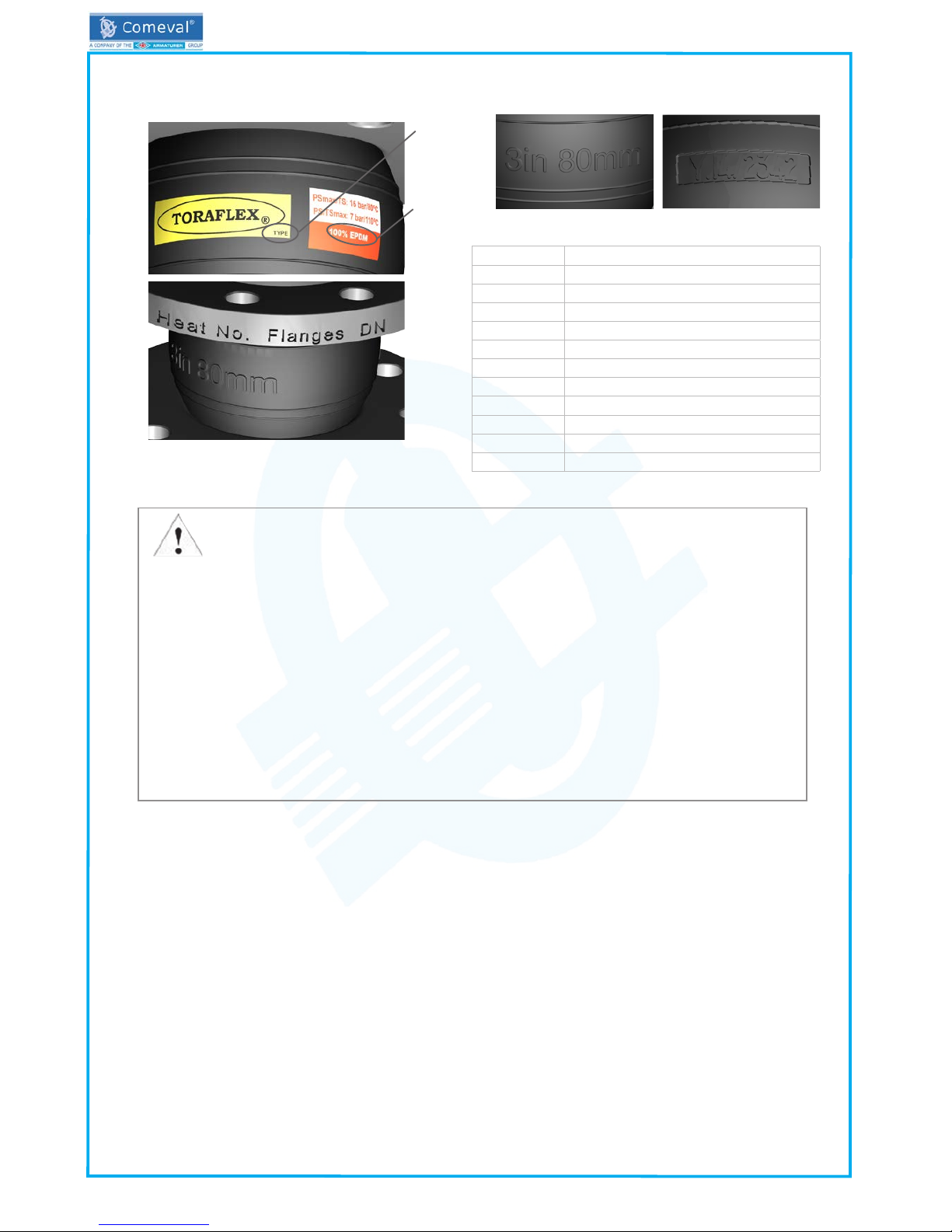
TORAFLEX®RubberJointsaredevisedforpipingworks,consistingofaexiblemainshellmadeofsyntheticrubberwith
innerreinforcementstoprovideconsistency,andpipeconnectionsbymeansoflooseangesorthreadedunions.They
canbeusedeithertoabsorbvibrationanddampennoisecausedbyequipmentsuchaspumpsorcompressors,orto
balancethermalmovementsinpipesystemsduetotemperaturechanges.Theyalsohelpatinstallationtobalanceslight
misalignmentsorlengthdeviationsandreducetheeffectscausedbywaterhammerstoacertainextent.Theyarewidely
used in HVAC, water treatments, process industry, ships, etc.
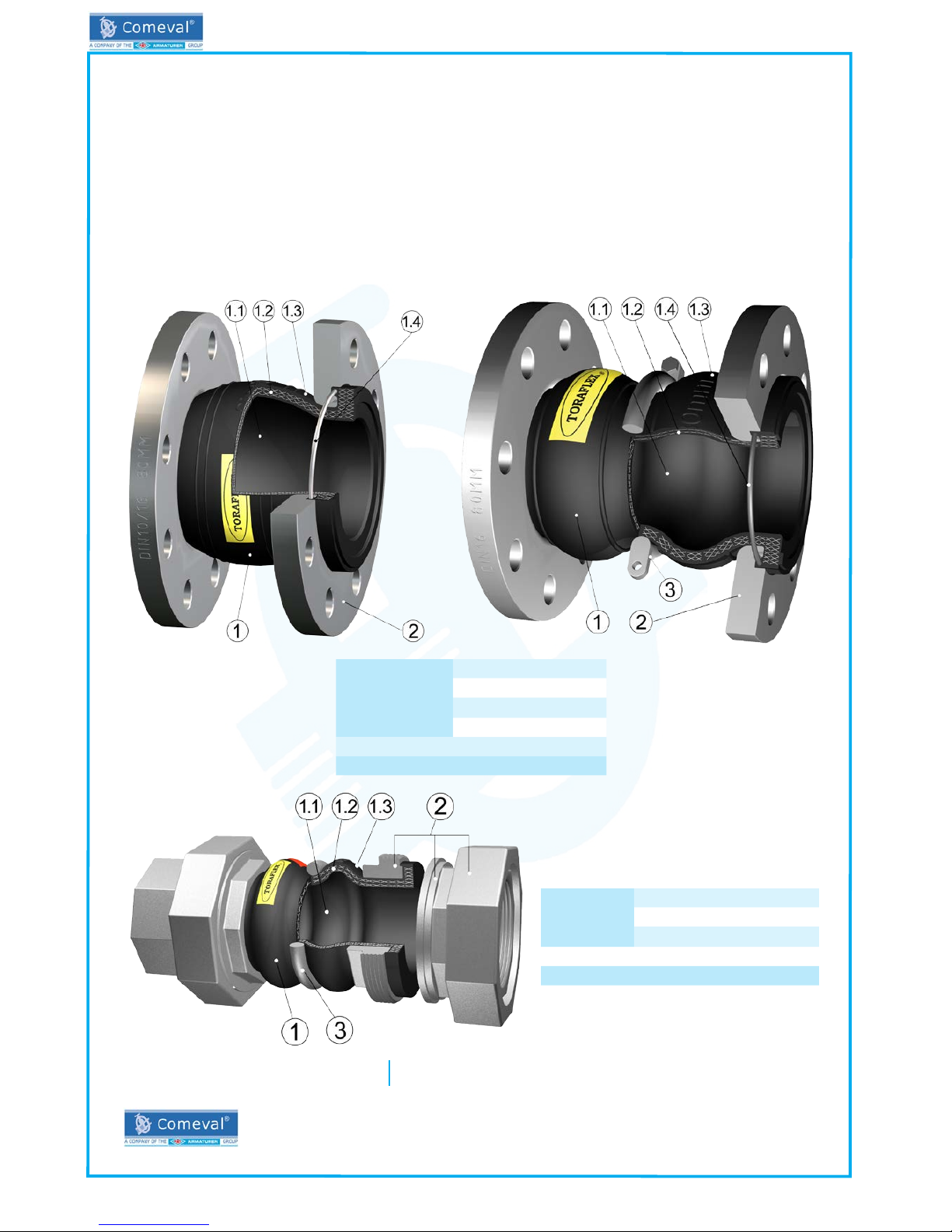
AdrawingofeachtypecanbeseenattheendoftheManual.
4.2Technicaldata-remarks
Checkproductselection,materialcompatibility,pressureandtemperaturelimitsandotheressentialparameters.Ensure
proper safety devices/measures are implemented to prevent exceeding intended use of the product. Refer to Data Sheet
for data such as main features, duties/limits of use, dimensions, weights, etc and consult the manufacturer for further
information.
- Protect against external force (impacts, vibrations, etc.).
- Allow only skilled personnel; suitable handling and lifting equipment must be used. See Data Sheet for weights
or consult manufacturer. Use gloves and other protection equipment to avoid cutting with sharp edges of ends
or rods.
- Always use suitable protection equipment, and minimize the use of human body force at any step to avoid
injuries.
- There is a risk of body member (hand, nger, arm…) crushed against any other solid element (wall, pipe, oor,
etc.) during handling. Take this into account and handle with care.

IOM - RUBBER JOINTS, TORAFLEX® S10/S15/S20/S30/S32
©COMEVAL VALVE SYSTEMS Technical Dept. Ref. IOM - RUBBER JOINTS, TORAFLEX® S10/S15/S20/S30/S32 - Ed.16/07
Comeval Valve Systems reserves the right to alter any technical data contained in this Manual without prior notice. Regularly updated data on www.comeval.es
Page 3
4.3Marking/label
Descriptionoflabeling/markingontherubber:
5. INSTALLATION
5.1Generalremarksoninstallation
Thefollowingpointsshouldbetakenintoaccountinadditiontothegeneralprinciplesgoverninginstallationwork:
-Werecommendnottopaintorlubricatetherubbers.
5.2Requirementsattheplaceofinstallation
-RubberJointsexposedtoweatherandoutdoorsconditions(sunlight,ozone,UVlight,etc.)agemoreprematurely.Con-
sider special construction/protective measures in such a case.
-Minimizewhenpossiblestrongthermalgradients.Apartforrubberaging,cyclictemperatureuctuationsmayalsolead
to loosening of unions.
-InDoubleSphereJoints(i.e.S20andS30types),useofrootringsmightbenecessarywithbigsizes,hotwaterand/
orworkingpressuresabove10bar.PleasecheckourDataSheetorconsultus.
-Considertheinteractionbetweenthesystemandtheequipment.Foreseeguides,anchoringandpropersupportaccor-
ding to the weight of the components.
-Thesystemandoperationprotocolshouldbeconceivedinsuchawaytoavoidhighvelocities.Preventpulsingowor
water hammers, which are very harmful for the whole pipe system.
- Flooding of the product is not recommended.
-AllowenoughspaceforRubberJointinstallation,operationandmaintenance.
-Considertheinteractionbetweenthesystemandtheequipment.ProperselectionandlocationoftheJoints,aswellas
proper guiding and anchoring of the system are essential for the safe and proper use of the Joint, as explained in detail
herebelow.
ATTENTION!
- Before installation, make sure previous chapters are thoroughly followed.
- Ensure safe access and working conditions for proper performance.
- Observe all applicable safety measures during installation.
- Remove ange covers or any other remaining packing/storage protection if present.
- Lay pipelines such that damaging transverse, bending and torsional forces are avoided.
- Protect equipment from dirt during construction work. The interior of the Rubber Joint and the pipeline must be
free of foreign particles.
- There is not preferred direction of ow. Rubber Joints are bidirectional. Rubber Joints can be installed in hori-
zontal and vertical pipelines.
- When installing the rubber joint, there is a crushing hazard between rubber joint and pipe system. Mind the
hands to avoid it.
- The introduction of electrical current, e.g. during electrical resistance welding, may cause the Joint to be destro-
yed. If there is a possibility that electrical currents may occur, the Joint shall be electrically bypassed.
- Elastomeric or uoropolymer surfaces should be cleaned if necessary with a wet cloth to avoid electrostatic
charge. Also consider the risk of electrostatic charges created by the ow.
Mark Description
TORAFLEX® Brand
FIG. Joint code (S10, S15…)
Y.VV Manufacturing year (Y.16 = 2016)
ZZZZ Batch no.
PSmax Max. pressure
TS Max. temperature at max. pressure
PS Max. pressure at max. temperature
TSmax Max. temperature
RUBBER Rubbermaterialinside/outside(EPDM,NBR…)
Flanges Flanged connection
SIZE/DN RubberJointsize(80mm=DN80)
FIG.
RUBBER SIZE Y.VV/ZZZZ

IOM - RUBBER JOINTS, TORAFLEX® S10/S15/S20/S30/S32
©COMEVAL VALVE SYSTEMS Technical Dept. Ref. IOM - RUBBER JOINTS, TORAFLEX® S10/S15/S20/S30/S32 - Ed.16/07
Comeval Valve Systems reserves the right to alter any technical data contained in this Manual without prior notice. Regularly updated data on www.comeval.es
Page 4
5.2.1Reactionforces.AnchoringandGuiding.LimitRods
REACTION FORCES
-Reactionforcebyinternalpressure:
RubberJointsareexiblecomponentswhichbreakthepipesystemrigidity.ARubberJointactsasapistonbythe
forcesarisingfromtheinternalpressureofthepipe.Topreventthepipesfromdamagetheyhavetobeproperly
anchoredinordertoabsorbthesereactionforces(Fr).
The reaction force caused by internal pressure in a Rubber Joint is
calculatedbythefollowingformula:
Fr (N) = P (kg/cm2) x A (cm2) x 10
Fr =Reaction Force
P = Pressure
(Max.WorkingPressureandTestingPressuremustbeconsidered)
A = Effective cross sectional area
Effective area for each Joint type is given in our Data Sheet.
Therestofreactionforcestobeabsorbedbysystemanchorsareasfollows:
-ReactionforcescausedbytheinnateJointresistancetomove,calculatedthroughtheJointstiffness,normallygiveninN/
mm (axial or lateral) and Nm/º (angular).
-Reactionforcescausedbythefrictionoftheguides.
-ApartfromreactionforcescausedbytheJointinstallationitself,pipesystemweightandcentrifugalforcesonbendscau-
sedbyvelocityoftheuidmustalsobeconsideredforanchoring.
ANCHORING. FIX POINTS
WecallFixPointstotheanchorsthatabsorbreactionforces.
EveryRubberJointhastobeinstalledbetweentwoFixPointswithinastraightpipe
section.
IntermediateFixPointsaretheonesjustabsorbingforcescausedbyJointstiffness
andfriction ofguides, whereasMain FixPoints alsoabsorb theforces causedby
internalpressure,centrifugalforcesandweightsnotsupportedbyGuides.
MainFixPointsarenormallylocatedinpumpgroups,valves,bends,crosses,lineendingorowchangesectionsofthe
pipe work.
GUIDING
Guidesnotonlysupportthepipesystemweight,butalsomaintaincorrectalignmentsothatthe
Joints work adequately. It is important to notice that Guides supporting the pipe system are not
FixedPoints.TheGuidesshouldbepositionedaccordingtocertainrulesgivenfurtheronandthey
preventbucklingoftheline. Special Guidescanbeusedtoallow movement in morethanone
direction.
LIMIT RODS
ThemainpurposeofLimitRodsistoabsorbtheforcecausedbyinternalpressure,andavoidreactionforceoverFixPoints.
FixPointswillbereleasedbuttheyarestillnecessary.AJointwithLimitRodswillworkonlywithaxialmovements.Theyare
normally used with high pressures and large DNs, that may require very strong anchoring. They also relieve pump frames.
LimitrodscancontrolJointbellowover-extensionand/orover-compression.
5.2.2InstallationGuidelinesforRubberJointsabsorbingvi-
brationandnoise
RubberJointsarecommonlyinstalledinpumpgroupstoabsorb
vibrationandnoise.TheRubberJointbeinstalledinitsrestpo-
sition.Donotoverstretchittollagapbetweencounteranges
andJointfaces.Alternativemeasuresshouldbetakeninsucha
case (modify pipe arrangement, spacer, etc.).
TheRubberJointmustbeinstallednearthepumpgroup,lea-
ving just 1-1,5 DN distance. Leave more distance in case of
abrassivemedia.
The Pump group frame must be properly anchored to absorb
thereactionforcesandanotherFixPointmustbesetimmedia-
telyaftertheRubberJointtolimitthevibrationsamplitudeonto
the pipe.
Proper guiding of the pipe is also necessary to ensure the equi-
pment works correctly.
Absorbingpipeexpansion/compressionmustbecarriedoutin-
dependently.
IncaseMainFixPointscouldnotbesizedtoabsorbthereac-
tionforcecausedbyinternalpressure,limitrodscanbeusedto
relieve them from such forces.
Fixed point welded for
pipes in parallel Fixed point for
elbow
Guide with roller stand
Joint under pressure acts as a piston.
Results shown when working without anchoring
Installation of Joints without limit rods

IOM - RUBBER JOINTS, TORAFLEX® S10/S15/S20/S30/S32
©COMEVAL VALVE SYSTEMS Technical Dept. Ref. IOM - RUBBER JOINTS, TORAFLEX® S10/S15/S20/S30/S32 - Ed.16/07
Comeval Valve Systems reserves the right to alter any technical data contained in this Manual without prior notice. Regularly updated data on www.comeval.es
Page 5
LimitRodsAssemblyonRubberJointsabsorbingVibrationandNoise:
1) Set the Joint in its rest position.
2)Placetheplatessymmetricallyontheexternalfaceofcounteranges,and
equidistantlytotheangedrillings.Fixplateswithnutsandboltsasshownin
the picture.
3) Introduce the rod through the third orice of each plate until it remains
centred with the Joint.
4)Introducearubbergasketfromeachsideoftherodandthenametalwasher.
5)Introducenutsfromeachsideoftherod,andxtheminthedesiredposi-
tion(preferably limitingthe Jointexpansion toits restposition) bymeans of
counter-nut or with a welding spot.
5.2.3InstallationGuidelinesforRubberJointsworkingasExpansionJoints
SelectionofExpansionJointsandpositioningofFixedPointsandGuidesinapipelinemustbestudiedatthesametime.
Werecommenddividingthecompletesystemintosimplecongurations.Thewholeselectiondependsonthemovements
tobeabsorbed,pipesystemlayout,possibilitiesforsettingFixedPointsandGuides,andExpansionJointstypetobe
used.
Asexplainedbeforewe have todifferentiatebetween the MainandIntermediateFixedPoints. Reaction forcestobe
absorbedbyanchorshavetobecalculatedandassignedtotheFixedPointsfortheircorrectdesign.
IncaseMainFixPointscouldnotbesizedtoabsorbthereactionforcecausedbytheinternalpressure,LimitRodscan
beusedtorelievethemfromsuchforces.
-CalculationofmovementstobeabsorbedbytheJoint:
A pipe undergoes and increases in dimensions when its temperature changes.
To calculate the change in length in a pipeline it is necessary to know what the
temperaturedifferentialwouldbeandtheexpansioncoefcientofthepipe.
Maximum movements allowed for each Joint type are stated in our Data Sheet.
-Establishingthebuildinginstallationlength:
TheJointmaybeinstalledinitsrestpositionorslightlycompressedtofavorthe
absorptionofmovementunderpipecontraction.Buildinglengthlimitsforeach
Joint type is shown in Data Sheet.
Installation of Joints with limit rods

IOM - RUBBER JOINTS, TORAFLEX® S10/S15/S20/S30/S32
©COMEVAL VALVE SYSTEMS Technical Dept. Ref. IOM - RUBBER JOINTS, TORAFLEX® S10/S15/S20/S30/S32 - Ed.16/07
Comeval Valve Systems reserves the right to alter any technical data contained in this Manual without prior notice. Regularly updated data on www.comeval.es
Page 6
HerewithsomeexamplesandrecommendationsforlocationofRubberJointsworkingasExpansionJointswithproper
anchoring and guiding.
LimitRodsAssemblyonRubberJointsworkingasExpansionJoints:
Installationaccordingtodrawingsandfollowingsimilarstepsdescribedabove.
-TocontrolJointcompression,innerrodnutscanbeused,xedwithaweldingspotorcounter-
nut,oralternativelyasleeveintheproperlengthcanbesetintherodpartbetweentheplates.
-TocontrolJointexpansion,outerrodnutscanbesetwithaweldingspotorcounternut.
-Limitrodscanalsobeusedtopre-expand(withinnerrodnuts)orpre-compress(withouterrod
nuts).Tighteningmustbeprogressiveanduniform.
LimitRodsAssemblyonRubberJointsworkingwithVacuum
Description of limit rods use in vacuum service in our Data sheets in www.comeval.es.
Followthesameprocedureexplainedabove,butplacingplatesontheinternalfaceoftheJoint
anges.InternalnutswillprecenttheJointtoshrinkduetovacuum.
5.2.4AssemblingtheJointtothepipe
-Removethestorageprotectioncarefullyifanyjustbeforeinstallation.
ATTENTION!
- Specialcareshouldbetakeninordernottodamagethesoftparts.
- Ensure that the Joint interior and the piping system are free from dirt, rust, pipe, scale, welding slag or any other foreign
material.Incaseofuseofcleaningproducts,makesuretheyarecompatiblewithmaterialofconstruction.
-StartinstallationoftheJointonlyonceallworkontheadjacentpipe(angeswelding,anchorssetting,etc)hasbeen
completedandcooleddown.RubberJointscaneasilybedamagedbyweldingsparksorheat,sharpobjects,etc.
-Avoidgradients,excessiverotationorpipemisalignmentthatcouldexceedthepermissiblemovementsoftheJointinuse.
ATTENTION!
- Make sure that Joint expansion/compression limits in our Data Sheet are not exceeded.
ATTENTION!
- MakesurethatJointbuildinglengthlimitsarenotexceeded.
- Torsional strain is not permitted.
Anchoring and guiding for Joints working as Expansion Joints

IOM - RUBBER JOINTS, TORAFLEX® S10/S15/S20/S30/S32
©COMEVAL VALVE SYSTEMS Technical Dept. Ref. IOM - RUBBER JOINTS, TORAFLEX® S10/S15/S20/S30/S32 - Ed.16/07
Comeval Valve Systems reserves the right to alter any technical data contained in this Manual without prior notice. Regularly updated data on www.comeval.es
Page 7
Installationposition:
-TORAFLEX®RubberJointscanbeinstalledeitherinhorizontalorverticalpipelines,subjecttoproperanchoringand
guiding.
5.2.5InstallationofRubberJointswithanges
ATTENTION!
- MakesurethatcounterangesarecompatiblewiththestandardoftheJointanges.
-EnsurethatcontactfacesofJointangesandcounterangesarefreeofgreaseandingoodcondition.
-Sealingsurfaces ofmatinganges shall becheckedto ensurethatthere is noriskof the rubberbondsbeing
damagedbysharpinsideedgesorprojectionsorrecesses.Thescrewlengthshallbeselectedtoensurethatthe
rubberbellowscannotbedamaged.Duringinstallationandoperation,theJointsmustbeprotectedfromradiated
heat and welding heat.
-Ensurepipealignment.Counterangesshouldtsmoothly.Makesurethatthegapbetweenthe2counteranges
hasenoughclearancetottheequipmentwithoutdamagingtherubberfaces(carefullyretractslightlycounteran-
gesifnecessary)but,nofreegapshallexistbetweenRubberJointfacesandcounterangesfaces.Jointsmaybe
damagedifstretchedduringassembly.
-Therubbershellitselfactsassealinggasket,sonoadditionalgasketshavetobeadded.
-Incaseofanylubricantused,makesureitiscompatiblewithrubbermaterial.
-TypesS10,S15,S20havelooseanges,rotable360º,whicheasesassembly.
-Tightenopposingnuts/boltsgraduallyaccordingtothefollowingsequence:
Themaximumtighteningvaluesgivenunderareforreference.Afterrsttightening,therubberrelaxesandstarting
torqueisloweragain.Applyamoderatetighteningtorqueatrstandonlyretightentocorrectanyleakage.Anex-
cessiveorirregulartorqueleadstorubberdamageandshortensJointlifespan.
-Maximumtighteningtorques:
RubberJointSize(DN) Maximumtighteningtorque(Nm)
≤DN80 60-70
DN100-300 80-90
DN350-600 80-120
DN700 150-230
DN800-900 230-280
DN1000 250-300
Payattentiontothefollowingrecommendations:
Counteranges contact faces should be
at. Do not use grooved counteranges.
Rubber can swell under operation. Make
sure bolts are set in such a way to avoid
the contact with the Joint rubber.
Counteranges should have correct ID
to prevent damage to rubber contact
face. Use a spacer with additional
gasket between Joint and counterange
when installing slip-on anges or
counteranges with different ID than
Joint, in order to avoid damage on the
rubber face. We strongly recommend
the use of welding neck counteranges
with correct ID.
Itisalwaysrecommendedthatpipelineandcounterangestohave90ºangleandbeperpendiculartoeachother.
Thisisamustforworkingpressuresabove10bartoavoidrubberdamages.

IOM - RUBBER JOINTS, TORAFLEX® S10/S15/S20/S30/S32
©COMEVAL VALVE SYSTEMS Technical Dept. Ref. IOM - RUBBER JOINTS, TORAFLEX® S10/S15/S20/S30/S32 - Ed.16/07
Comeval Valve Systems reserves the right to alter any technical data contained in this Manual without prior notice. Regularly updated data on www.comeval.es
Page 8
5.2.6InstallationofRubberJointswiththreadedends
ATTENTION!
MakesurethatthepipescrewhasthecorrectnishandcompatibleconewiththeJoint.
-Usepropersealantaccordingtoduty,suchashempcore,Teon,etc.
- Check that pipe introduction in the Joint does not exceed valve thread, leave at least 1 mm as safety margin.
-TightenwithaplainoradjustablewrenchonthehexagonendoftheJointonly.Applyforcetoanyotherareamay
seriously damage it. Do not use hook spanners or other wrenches that could damage the hexagon surface. It should
bethreadedsmoothly.Ifnot,donottrytoforcethethreadandavoidwrenchextensionssincethiscouldleadto
breakingthevalveordamagingthethread.Tighteningmustbemoderate.Overtighteningtheunioncouldcause
rubberbreakorstretching.
-Planners/constructioncompaniesortheownerareresponsibleforpositioningandinstallingproducts.
6. COMMISSIONING & OPERATION
ATTENTION!
- Before commissioning the equipment, check the material, pressure, temperature, media and other essential para-
meters. Always use the product within the scope of intended service and operating duties. Check our Data Sheet.
- Water treatment chemicals may attack Joints materials. Before adding these kind of chemicals, make sure they
will not damage the Joints and consult us and our Data Sheet when needed. In any case even chemicals suitable
for elastomers may only be added in the proportions of ingredients specied by the manufacturer of chemicals.
- Before commissioning, make sure previous chapters have been thoroughly followed.
- It is essential to ush the pipe system thoroughly to eliminate all the particles and impurities which could remain in the pi-
pes and particularly welding residue, chips, tool remains, etc. that could damage the equipment during start-up. Ensure
that during cleaning of the pipe system, any chemicals used and temperature are compatible with the Joint construction.
- Regional safety instructions should be adhered to.
- Temperatures above 50ºC or below 0ºC may cause personnel injuries if Joints are touched.
- Leakage of media through Rubber Joint or between counteranges may also cause scalding, health harm, pollu-
tion, re or damage to other parts of the installation depending on the media.
Use suitable protection equipment when approaching the rubber joint, ensure that the corresponding warning signs
are displayed on the rubber joint or surrounding area, and/or isolate the equipment in case of danger.
- Before commissioning a new plant or restarting it after repairs or modication, always ensure that:
- All work has been completed correctly.
- The Joint is in the correct position for its function.
- Safety devices/measures have been implemented.
- Check for tightness in Joint/pipe connections. For anged Joints, retighten ange union bolts/nuts crosswise and
gradually if necessary until leakage elimination. If leakage persists, correct alignment and centring of the equipment
should be checked, and surfaces should be thoroughly cleaned. If contact surfaces are irreversibly damaged re-
place them. For threaded Joints in case of leakage between swivel unions, retighten slightly and progressively until
leakage disappears.
-Inspectguidestodiscardjamming.
-Incaseofriskofmediafreezinginsidetherubberjoint,takeduemeasurestoavoidit.
-Maximumrecommendedhydraulictestpressure1,1xPN(PSmaxmarkedintherubberbellow).TestPressuremedium
tobewateratroomtemperature.
ATTENTION!
- Overtightening the unions may cause rubber damage and reviews life span of the Joint. In case of leakage re-
tighten onlly until achieving tightness.
- In case of hydraulic test above PSmax, please double check the reaction forces and anchoring sizing.
- Torsional strain to be avoided during commissioning and operation.

IOM - RUBBER JOINTS, TORAFLEX® S10/S15/S20/S30/S32
©COMEVAL VALVE SYSTEMS Technical Dept. Ref. IOM - RUBBER JOINTS, TORAFLEX® S10/S15/S20/S30/S32 - Ed.16/07
Comeval Valve Systems reserves the right to alter any technical data contained in this Manual without prior notice. Regularly updated data on www.comeval.es
Page 9
7. CARE AND MAINTENANCE
Theoperatormustdenemaintenanceandmaintenance-intervalstomeetrequirements.
-Checkforbodyandconnectionstightness.
ATTENTION!
- Only carry out maintenance work in the pipework when all safety measures have been taken.
- When inspecting and replacing the Joint check working parameters, material compatibility, anchoring and guiding,
etc. In general note chapters 5 & 6.
- If there is leakage through unions, refer to chapters 5 & 6. Unions may loosen for example in case of temperature
cycling or during shut-down times, and periodical retightening may be needed.
-CheckthatJointisworkingproperlywithoutjammingordamageofmechanicalcomponents(bellow,tierods).Check
that there is no dust or other deposits compromising the proper functioning of the equipment.
- Check that anchoring and guiding of the pipe work are in good condition.
- In case of limit rods are installed, check that the nuts on the rods limiting expansion/compression have not moved due
tovibrationsandthattheyarenotweakenedbycorrosion.Ifgussetplatesorthreadedrodsarebentordistorted,thisis
a symptom of over-elongation or over-compression.
-Rubberbellowshouldbepreventivelyreplaced.Correspondingintervalsshouldbedenedandscheduledbytheplant
operationpersonnelaccordingtoservicelevel.Therearemanyfactorsinuencingthelifeexpectancy,suchasinsta-
llation arrangement, temperature, pressure, movements absorbed, cycles, environmental exposure, media, ow rate,
storageperiodpriortoinstallation,etc.tobeevaluatedaltogether.Lifeexpectancyofajointproperlyhandledandinsta-
lledandworkingundernotharshserviceconditionsmaybeestimatedintherangeof3-5years.
Replacingthebellowrubber:
Jointshouldbecarefullyanchoredtoabench.Withtheassistanceofspecialshapewrenches(hookendtype)therubber
neckmustbeslippedprogressivelyundertheangebydeformation.Repeattheoperationattheotherend.Placethe
newbellowinverselymakingsureitisnotdamagedduringtheassembly.
After any maintenance work please refer to chapters 5 and 6 for installation / commissioning.
ATTENTION!
- Do not use wrenches or tools with sharp ends that could damage rubber surfaces.
RecommendedSpareparts:
Whenitisneededtoreplacetherubberbellow,existingangedunionscanbereusedifingoodcondition,althoughitis
often more practical to replace the whole unit.
8. DISMANTLING THE JOINT
ATTENTION!
The following points must be observed:
- Pressureless pipe system.
- Medium must be cool.
- Plant must be drained.
- Note chapter 3 for proper handling and lifting.
- Additionally, in case of toxic, corrosive, ammable or caustic media:
- Purge pipe system carefully.
- Use proper protection equipment to avoid health harm.
- Adopt proper actions to avoid pollution of the environment.
9. GOODS RETURN & DISPOSAL
-Foranyreturnedgoods,theissuingcompanymustprovideinformationinwrittenonanyhazardsandtheprecautionin
case of potentially polluting or harmful residues, or any mechanical damage that could present a health, safety or environ-
mentalrisk,asenforcedbyEUHealth,SafetyandEnvironmentLaw,includingtheSafetyDataSheetsofthesubstances
identiedaspotentiallyhazardous.
-RubberJointsmaterialsrepresentahazardtotheenvironmentandshallbedisposedbyspecializedcompanybyap-
proved procedure. Incineration is not permitted.
10. WARRANTY / GUARANTEE
-Theextentandperiodofwarrantycoverarespeciedinthe“GeneralSalesTerms”ofCOMEVALVALVESYSTEMS
validatthetimeofdeliveryor,bywayofdeparture,inthecontractofsaleitself.
-Weguaranteefreedomoffaultsincompliancewithstate-of-the-arttechnologyandtheconrmedapplication.
- No warranty claims are accepted for any damage caused as the result of incorrect handling or disregard of this Manual,
Data Sheet and relevant regulations.

IOM - RUBBER JOINTS, TORAFLEX® S10/S15/S20/S30/S32
©COMEVAL VALVE SYSTEMS Technical Dept. Ref. IOM - RUBBER JOINTS, TORAFLEX® S10/S15/S20/S30/S32 - Ed.16/07
Comeval Valve Systems reserves the right to alter any technical data contained in this Manual without prior notice. Regularly updated data on www.comeval.es
Page 10
- This warranty also does not cover any damage which occurs during operation under conditions deviating from those laid
downbyspecicationsorotheragreements.
-Justiedcomplaintswillbeeliminatedbyrepaircarriedoutbyusorbyaspecialistappointedbyus.
-Noclaimswillbeacceptedbeyondthescopeofthiswarranty.Therighttoreplacementdeliveryisexcluded.
- The warranty shall not cover maintenance work.
- Our guarantee coverage does not cover for any commissioning, maintenance or installation of the product or external
parts.
-Ourguaranteedoesnotcoverproductsprovedtohavebeentamperedwithorfaultedbymaterialwearandtear.
-ThePurchaserisresponsibleforcheckingthattheincomingproductisreceivedingoodconditionandconformstothe
orderedspecications.Incaseofdamagecausedduringtransititisnecessarytoimmediatelycomplaintothecarrier
within 24 hours. After this time carriers could not assume the derived costs. In case of any deviation in relation to order
specications,pleasecontactus.
11. PARTS LIST
1-VULCANISED
RUBBER
BELLOW
1.1Rubbercore(inner)
1.2 Nylon tire cord
1.3Rubbercover(outer)
1.4 Hard steel wire
2-LOOSEFLANGES
3-ROOTRING(option)
S30
1-Vulcanised
rubber
bellow
1.1Rubbercore(inner)
1.2 Nylon tire cord
1.3Rubbercover(outer)
2-Unionswiththreadedends
3-Rootring(option)
12. ANNEXES
12.1 DeclarationofConformity-DC13EN
12.2 DataSheet-DS13
COMEVALVALVESYSTEMS,S.L.yCIA.,Soc.Comanditaria
Les Rotes, 15 46540 El Puig (Valencia) España
Phone+34 961 479 011 ·Fax+34 961 472 799
S10/S15 S20
Updated documents on www.comeval.es
This manual suits for next models
3
Table of contents
Popular Power Tools manuals by other brands

Husky
Husky H3DTWDIG owner's manual

SIEGEN
SIEGEN s0100 instructions

Ingersoll-Rand
Ingersoll-Rand 1712 Series Product information

Desoutter
Desoutter SD Series Servicing and operating instructions

Atlas Copco
Atlas Copco ETV ST61-100-13 Original product instructions

King Canada
King Canada KSB-10 instruction manual