Atlas AE 45 User manual

AE 45
OpErAting instructiOns
MEtric tOOl

2 PennEngineering • www.pemnet.com
• Readtheinstructionscarefullybeforeusingthetool.
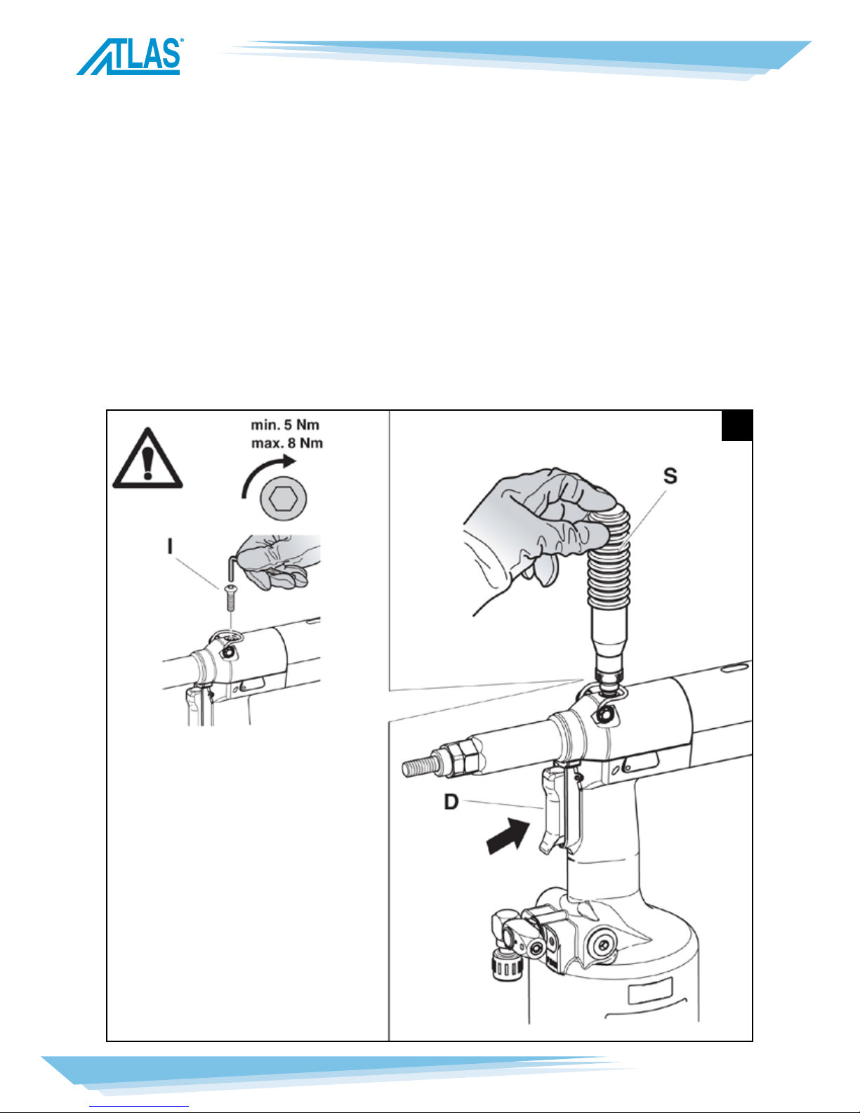
• Forallmaintenanceand/orrepairspleasecontactPennEngineeringanduseonlyoriginalspareparts.
PennEngineeringmaynotbeheldliablefordamagesfromdefectivepartscausedbyfailuretouse
orginalspareparts.
• Thetoolmustbeusedonlybyexpertworkers.
• Aprotectivevisorandglovesmustbeputonwhenusingthetool.
• Useequipmentrecommendedinthemaintenancechaptertodoanymaintenanceand/orregulationof
thetool.
• Fortoppingofftheoil,wesuggestusingonlyuidsinaccordancewiththefeaturesspeciedinthis
workingbook.
• Ifanydropofoiltouchesyourskin,youmustwashwithwaterandalkalinesoap.
• Thetoolcanbecarriedandwesuggestputtingitintoitsboxafterusing.
• Thetoolneedsathoroughsix-monthlyoverhaul.
• Repairingandcleaningoperationsmustbedonewhenthetoolisnotfed.
• Ifitispossible,wesuggestasafetybalancer.
• ThetoolismadesothatacousticpressurelevelcontinuousequivalentweightedAisnotmorethan75
dB(A)wherepeopleworks.
• Ifthenoiselevelismorethan85dB(A),youmustusesomehearingprotections(anti-noiseheadset,
etc.).
• Theworkbenchandtheworksurfacemustbealwayscleanandtidy.
• Donotallowunauthorizedpersonstousetheworkingtools.
• Makeyousurethatthecompressedairfeedinghoseshavethecorrectsizetobeused.
• Donotcarrytheconnectedtoolbypullingthehose.Theholemustbefarfromanyheatingsourcesor
fromcuttingparts.
• Keepthetoolsingoodconditions;donotremoveeithersafetypartsorsilencers.
• Afterrepairingand/oradjusting,makesureyouhavealreadyremovedtheadjustingspanners.
• Beforedisconnectingthecompressedairhosefromthetoolmakesurethatthereisnopressureinthe
hose.
• Theseinstructionsmustbecarefullyfollowed.
GENERAL NOTES AND USE
ThetoolcanbeemployedonlyforthreadedinsertswiththreadofM4toM12diameter.TheAE45oil
pneumaticsystemassuresmorepowerthanthepneumaticsystemusedforothermodels.Thatmeansa
reductionintheproblemsduetothewearandtearofthecomponents,therefore,therewillbeanincrease
inreliability.Thetechnicaisolutionsadoptedreducethedimensionsandtheweightofthetoolwhich,for
thesereasons,makeitveryhandy.Thepossibilitiesofleakagefromtheoil-dynamicsystem,areeliminated
bysomesealedgaskets,whichsolvethisproblem.
SAFETY MEASURES AND REQUIREMENTS

PennEngineering • www.pemnet.com
3
A)........................................................................................................................................ Threadedtierod
B)...........................................................................................................................................................Head
C).............................................................................................................................Ring-nutclampinghead
D).................................................................................................................................. Controlpush-button
E)...................................................................................................................... Compressedairconnection
F)................................................................................................................................Pressurecontrolvalve
G)..................................................................................................................................... Protectionbottom
H)........................................................................................................................................Pneumaticmotor
I)............................................................................................................................................... Oiltankplug
L).................................................................................................................................. Balancerconnection
M).............................................................................................................................. Stroke-adjustingknob
N)........................................................................................................................................ Strokeindicator
O).....................................................................................................................................Tubecarryinghead
P)............................................................................................................................. Forcedunscrewingrod
1
MAIN COMPONENTS

4 PennEngineering • www.pemnet.com
• Workingpressure...................................................................................................................... 6-7BAR
• Min.int.diam.ofthecompressedairfeedinghose............................................................ømin.=8mm
• Maxfreeairconsumptionpercycle.................................................................................................. 11NI
• Force(6BAR)................................................................................................................................. 28KN
• Noise.........................................................................................................................................<75db(A)
• Weight(withequipmentforM10)................................................................................................... 2.9Kg
• Workingtemperature.................................................................................................................–5°/+50°C
• Rootmeansquareintotalaccelerationfrequency(Ac)
towhichthearmsaresubjected............................................................................................ <2.5m/sec2
AIR FEED
Thecompressedairsystemmustbeprovidedwithaircleanersandcondensationdrainsandmustguaran-
teethattheairsuppliedtothefeederhasaconstantpressureofmin6bars.Theregulatormustbesetata
pressureof6.5bars.
Connectthemachinetothemaincompressedairsupplyasshowninthediagram(2):
1)Stopcock(usedduringmaintenanceoftheregulatorlterorofthelubricatingunit)
2)Mainsupplyinlet
3)Mainsupplybleed
4)Pressureregulatorandlter(bleeddaily)
5)Lubricatingunit
2
TECHNICAL DATA

PennEngineering • www.pemnet.com
5
Checkthatthethreadedtierod(A)andhead(B)coupleassembledontherivetingtoolissuitabletothe
sizeoftheinserttoclamp;otherwisechangethesize.Thecoupletierod(A)+head(B)assembledonthis
rivetingtool,correspondstoaM10thread.Beforeusingtherivetingtoolandaftereachchangeofsize,the
strokeshouldbeadjustedaccordingtothedimensions,sizeoftheinsertandthicknessofthematerialto
clamp.Beforecarryingoutthisoperationrotatetheknob(M)accordingtothedirectionofthearrow,(+)for
increasingthestrokeand(-)fordecreasingit.Increasingthestroke[rotationofknob(M)]inthedirection
indicatedwiththesymbol(+),thedistance“h”decreasesincreasingtheclampingaction.Forverifyingthat
thestrokeiscorrectlyadjustedchecktheindicator(N)[comparingitwiththevaluesofthetable(g.3)].
NOTE: Before the definitive placing of the insert, its clamping on the thicknesses involved should be
checked, carrying out other adjustments, as shown at page 9 (the specified adjustments are just an indica-
tion, it is advisable to see the technical data of the inserts used).
3
PRELIMINARY OPERATIONS

6 PennEngineering • www.pemnet.com
Checkthatthethreadedtierod(A)andhead(B)coupleassembledontherivetingtoolissuitabletothe
sizeoftheinserttobeused.Adjustthestrokeasindicatedonpage5.Introducetheinsertonthetierod
(A)andpushslightlyonitasindicatedingure4,soastomakeitclampautomaticallyonthethreaded-tie
rod.Makesurethattheinsertheadtouchesthehead(B)checkingthatthetierod(A)comesoutof2mm
fromtheinsert.Incaseoffurtheradjustmentsofthetierod(A)followtheinstructionsofpage9.
Itispossibletoplacetheinsertpushingthebutton(D)andkeepingitpusheduptothecompleterelease
ofthetierod.Foracorrectplacingandrightworkingofthemachine,theinsertstobeusedshouldbe
properlycleaned.
NOTE:According to the desired clamping, carry out other adjustments of the riveting tool stroke, rotating
the knob (M) (page 5), if necessary.
Insufficient deformation =the insert could rotate inside the housing compromising its use and resistance.
Excessive deformation = possible damages of the insert and tie rod (A) with eventual breaks of both com-
ponents.
45
6
PLACING OF THE INSERT

PennEngineering • www.pemnet.com
7
Whentheconditionscauseaforcedunscrewingofthetierodfromtheinsert,actasfollows:
removethepushrod(P)fromitsseat(1)andintroduceitintotheholeinthelowerpartofthetensile-
strengthbuttonpushingitslightly(2).
WARNING! Carry out this operation keeping the riveting tool firmly in order to avoid sharp movements
which could cause injury or damage (3).
Whenthetierodisfreefromtheinsert,puttherodbackinitsseatfornotloosingit(4).
WORKING PROBLEMS

8 PennEngineering • www.pemnet.com
Therivetingtoolissuppliedwith6pairsofthreadedtierods(A)andheads(B),fortighteningarangeof
threadedinsertsfromM4toM12.Dependingonthethreadsize,itisnecessarytoreplacethethreaded
tierod(A)andhead(B)group,asfollows:loosentheringnut(C)witha22mm.standardspannerand
removetherivetingtoolhead(B)[andspacer(Q)ifitrangesfromM4toM8].Withthesamespanner,
unscrewthetubecarryinghead(O).Usetwo20mm.standardspannersfordisassemblingtheringnut
(K)andextractthethreadedtierod(A).
NOTE: Use two spanners for unblocking the ring nut (K) as indicated in figure (9); the inobservance of this
procedure can damage the riveting tool.
Afterhavingreplacedthethreadedtierod(A)withthatoneoftherightsize,assembletheringnut(K)
againandcarryouttheabove-mentionedoperationsinreverseorder,beingsurethatthecomponent(R)is
therightone.Everytimeyoucarryoutanychangeofsize,repeattheadjustmentoperationsasindicated
onpage9.
78
910
CHANGE OF SIZE

PennEngineering • www.pemnet.com
9
Changingthelengthoftheinserttoclamp,thepositionofthehead(B)comparedtothethreadedtierod
(A)shouldbeadjusted.Disconnecttherivetingtoolfromthecompressed-airsupply.
Screwaninsertofthedesiredlengthonthethreadedtierodmanuallyuntiltheinsertheadtouchestheriv-
etingtoolhead(B).Theheadisadjustedcorrectlyifthethreadedtierodcomesoutoftheinsertscrewed
onitofabout2mm.Otherwiseunblocktheringnut(C)witha22-mmstandardspannerthenscrewor
unscrewthehead(B)uptotherightposition,andblocktheringnut(C).
11
12 13
ADJUSTMENT OF THE COUPLE TIE ROD/HEAD

10 PennEngineering • www.pemnet.com
Theoil-dynamiccircuitshouldbetoppedupafteralongperiodofworkorwhenthereisapowerlossof
therivetingtool.Puttherivetingtool(notfed)inaverticalpositionrotatingtheknob(M)towardsthesign
“+”uptotheendofstroke,andremovetheplug(I)bymeansofa4mmAllenwrench(equipped).During
thisoperationchecktheoillevelinordertoavoidanyoverowing.ThenpourtheoilVISCOSITY32°into
theoilcontainer(S)(equipped)whichshallbescrewedtoitsseatontheplug(I).
Whilekeepingtherivetingtoolinverticalpositionandstartingairfeeding,pushthebutton(D)andmake
therivetingtoolcarryoutsomecyclesuntilairbubblesinsidethecontainerstopcomingout.Thiscondi-
tionindicatesthatthetoppingupoftheoilhasbeenfullyachieved.Atthispointstoptheairfeedingand
whilekeepingtherivetingtoolinaverticalposition,unscrewandclosetheoilcontainer(S)andtheplug
(I)checkingthesoundnessofthehermeticwasherandrepeatalltheadjustmentsforplacingtheinsertas
indicatedatpage5.
WARNING: It is very important to follow the above-mentioned instructions and use gloves during oil top-
ping off. If you need to empty completely the hydraulic circuit, you must put the oil in a suitable container
and contact a company authorized to dispose of wastes.
14
TOPPING UP THE OIL-DYNAMIC CIRCUIT

PennEngineering • www.pemnet.com
11
Daily maintenance
•Checkthatthethreadedtierodisnotdamaged
•Checkthesupplysystemofthecompressedair
•Checkthatthestrokeofthetoolissuitablefortheselectedinserttoclamp(seethepertaininginstruc-
tionsforadjustingthestroke,indicatedatpage5).
•Checkthatthereareneitherairnoroilleakages.Inthiscasereplacepossibledamagedconnectorsor
seals
•Checkthatthesupplypressureofthecompressedairdoesnotexceed7bar.
Weekly maintenance
•Checktheoillevelcontrollingthestrokeoftherivetingtool.Ifnecessaryllupforpreventingfailuresof
therivetingtoolasindicatedatpage10.
Overhaul of the riveting tool
Itisadvisabletocarryoutacompleteoverhauloftherivetingtoolafter600,000cyclesoreveryyear.
InthiscaseapplyonlytocentresauthorizedbyPennEngineering.
MAINTENANCE

12 PennEngineering • www.pemnet.com
SPARE PARTS

PennEngineering • www.pemnet.com
13
NO. CODE QTY. DESCRIPTION
01 713291 1 HeadM10
02 71C00281 1 ScrewTCEIM10x70UNI5931
03 713176 1 HexagonalreductionM10
04 713292 1 HeadM12
05 713177 1 TierodM12
06 713030 1 HexagonalreductionM8-M12
07 713290 1 HeadM8
08 71345277 1 Spacerforscrew
09 71C00514 1 ScrewTCEIM8x70UNI5931
10 713289 1 HeadM6
11 71345276 1 Spacer
12 71C00279 1 ScrewTCEIM6x70UNI5931
13 713029 1 HexagonalreductionM6
14 713288 1 HeadM5
15 71345275 1 Spacer
16 71C00278 1 ScrewTCEIM5x70UNI5931
17 713027 1 HexagonalreductionM5
18 713287 1 HeadM4
19 71345274 1 Spacer
20 71C00277 1 ScrewTCEIM4x65UNI5931
21 713025 1 HexagonalreductionM4
22 709033 1 Vase
23 75036001 1 Instructionsforuse
24 72A00053 1 Oilcontainer
25 712225 1 Allenscrew4mm
NO. CODE QTY. DESCRIPTION
KIT A 74000026 1 Pneumatic Kit
01 71C00297 2 GasketOR6-700PARKER(N674-70)
02 713400 7 GasketOR-5-616PARKER(N674-70)
03 71C00355 2 GasketOR1.78x8.73(N674-70)
04 71C00356 2 GasketOR1.78x7.66(N674-70)
05 710921 1 GasketOR2-115PARKER(N674-70)
06 713399 1 GasketOR-5-614PARKER
07 71C00295 1 RingPARBAK8-028N300-90PARKER
08 71C00296 1 GasketOR5-670PARKER(N674-70)
09 710925 1 GasketOR027DOWTY(N674-70)
10 711062 1 GasketOR-2-126PARKER(N674-70)
11 710244 1 GasketOR-2-130PARKER(N674-70)
12 713275 1 GasketOR-2-122PARKER(N674-70)
13 710367 1 GasketOR2-008PARKER(N674-70)
14 710258 1 GasketOR-5-612PARKER(N674-70)
15AC 711338 2 GasketOR-2-003PARKER(N674-70)
16 710528 1 GasketOR008DOWTY
17AD 710918 2 GasketOR-2-005PARKER(N674-70)
18 710572 1 GasketOR2-120PARKER(N674-70)
19 710385 2 GasketOR2-006PARKER(N674-70)
20 713394 1 GasketOR2-106PARKER(N674-70)
21 710376 2 GasketOR2-009PARKER(N674-70)
22AB 716060 5 GasketOR2-010PARKER(N674-70)
23 713390 2 GasketOR2-007PARKER(N674-70)
26 710931 1 GasketOR-5-615PARKER(N674-70)
27 710914 1 GasketOR-2-116PARKER(N552-90)
28 710350 1 GasketOR2-109PARKER(N674-70)
29 713398 1 GasketOR-2-340PARKER(N674-70)
30 713192 5 Cage
KIT B 74000027 1 Tie rod container kit
KIT Q 74000037 1 Oil-dynamic kit
01 711827 1 GasketTS12-19-5.7/L
02 710390 1 GasketBALSELEB0750471
03 711722 1 GasketBALSELEB094063(B-NEI)
04 713389 1 GasketBALSELEB157118(B-NEI)
KIT
KIT indicates that the part is sold in kits consisting
of different parts in different quantities.

14 PennEngineering • www.pemnet.com
SPARE PARTS

PennEngineering • www.pemnet.com
15
NO. CODE QTY. DESCRIPTION
26 711722 1 GasketBALSELEB094063(B-NEI)
27 713402 1 SeegerringJV-25
28 71345258 1 Jacket
29 71345261 1 Flange
30 71C00295 1 RingPARBAK8-028N300-90PARKER
31 71C00296 1 GasketOR5-670PARKER(N674-70)
32 710925 1 GasketOR027DOWTY(N674-70)
33 71345264 1 Oil-dynamicpiston
34 713389 1 GasketBALSELEB157118(B-NEI)
35 711062 1 GasketOR-2-126PARKER(N674-70)
36 71345260 1 Ringnut
37 710244 1 GasketOR-2-130PARKER(N674-70)
38 713275 1 GasketOR-2-122PARKER(N674-70)
39 713348 1 MotorAM-0001
40 72A00022 1 Valveunitformotorcontrol
41 71345263 1 NutM16x1
42 71345265 1 Reduction
43 713333 1 Springfortie-rod
44 71345259 1 Drivingshaft
45 71345271 1 Tie-rodringnut
46 71345266 1 CannottoTubeCanneRöhrchen
47 713170 6 Ringnut
48 716198 1 ScrewTCEIM4x12UNI5931
49 72A00009 1 FendermotorProtection
50 710555 1 WasherERM400-004-4490
51 713405 1 ButtonheadscrewM6x10UNI-ISO7380
52 72A00043 1 Push-buttonBouton
53 713308 2 Cap
54 713406 2 ScrewTSEIM4X25UNI5933
55 72A00007 1 Airconnector
56 713390 2 GasketOR2-007PARKER(N674-70)
57 716150 2 ScrewTSEIM4x12UNI5933
58 710258 1 GasketOR5-612PARKER(N674-70))
59 710921 1 GasketOR2-115PARKER(N674-70)
NO. CODE QTY. DESCRIPTION
KITC 74000024 1 Oleodynamiccylinderkit
KITD 74000025 1 Hookkit
KITE 74000021 1 Silencerkit
KITF 74000029 1 Rodkit
KIT indicates that the part is sold in kits consisting
of different parts in different quantities.

16 PennEngineering • www.pemnet.com

PennEngineering • www.pemnet.com
17
NO. CODE QTY. DESCRIPTION
60 710528 1 GasketOR008DOWTY
61 710572 1 GasketOR2-120PARKER(N674-70)
62 710385 2 GasketOR2-006PARKER(N674-70)
63 713394 1 GasketOR2-106PARKER(N674-70)
64 713401 1 RollerNRBø3x19.8
65 710376 2 GasketOR2-009PARKER(N674-70)
66 74000020 1 Push-buttonunit
NO. CODE QTY. DESCRIPTION
KITH 74000033 1 Upperpistonkit
KITI 74000034 1 Lowerpistonkit
KITL 74000035 1 Retainingplatekit
KITM 74000036 1 Handgripkit
KIT indicates that the part is sold in kits consisting
of different parts in different quantities.

18 PennEngineering • www.pemnet.com

PennEngineering • www.pemnet.com
19
NO. CODE QTY. DESCRIPTION
67 72C00003 1 Body
68 713403 1 Ballø5.5
69 71345272 1 Valvecap
70 71345273 1 Coil
71 713400 1 GasketOR-5-616PARKER(N674-70)
72 71345299 1 Airconnector
73 71C00355 2 GasketOR1.78x8.73(N674-70)
74 71C00356 2 GasketOR1.78x7.66(N674-70)
75 713304 1 Guidestemconnector
76 711827 1 GasketTS12-19-5.7/L
77 710390 1 GasketBALSELEB075047
78 710931 1 GasketOR-5-615PARKER(N674-70)
79 710914 1 GasketOR-2-116PARKER(N552-90)
80 713319 1 NutM22X1.25
81 713320 1 Connector
82 713315 1 Stem
83 713197 1 Cover
84 713194 1 Knob
85 713316 1 Ringnut
86 713191 1 Disc
87 712575 1 ScrewTSEIM5X12UNI5933
88 713404 4 TappingscrewTSPø2.5x12forplastic
89 713317 1 Flangedconnector
90 713318 1 Drivingshaft
91 713321 1 Double-threadscrew
92 713322 1 ScrewM5
93 716060 1 GasketOR2-010PARKER(N674-70)
94 713199 1 Spring
95 713196 1 Protectionbottom
96 713434 2 Seegerringø11UNI7435
97 71C00297 2 GasketOR6-700PARKER(N674-70)
98 713398 1 GasketOR-2-340PARKER(N674-70)
99 710350 1 GasketOR2-109PARKER(N674-70)
100 72A00020 1 Overpressurevalveunit
101 72A00029 1 Airconnectorunit
NO. CODE QTY. DESCRIPTION
KITN 74000030 1 Pneumaticpistonkit
KITO 74000031 1 Pneumaticjacketkit
KITP 74000023 1 Coilkit
KIT indicates that the part is sold in kits consisting
of different parts in different quantities.

20 PennEngineering • www.pemnet.com
NO. CODE QTY. DESCRIPTION
1 71345183 1 Crowngear
2 71345382 1 Gearcage
3 71345181 4 Planetarygear
4 71345182 1 Planetarygear
5 71345180 1 Connector
6 71C00154 1 Bearing688ZZ
7 71345179 1 Frontcap
8 71345176 1 Outsidebody
9 71345171 1 Rollpin
10 71345177 5 Tongue
11 71345173 1 Rotor
12 71345172 1 Backcap
13 710943 1 Bearing624ZZ
A 713348 1 Completemotor
©2010 Rev. 510
Table of contents
Other Atlas Power Tools manuals
Popular Power Tools manuals by other brands

Westfalia
Westfalia S1C-ZP-125 Spare Parts Book and Instruction Manual

DeWalt
DeWalt DCS356E1T Original instructions

Makita
Makita HM0830T instruction manual

Kyocera
Kyocera TJEP HA-35 GAS 3G manual

Aimco
Aimco AcraDyne 1000 Series Operation manual

Parkside
Parkside POFA 12 A2 Translation of the original instructions