Comfee MPPH-10CRN1-BI0 User manual

model no. MPPH-06CRN1-BI0
AIR CONDITIONER
Instruction Manual
Toll-free: 1-866-646-4332
IMPORTANT: Before using your air conditioner, please
read this manual carefully and keep it for future reference.
PORTABLE
Downloaded from www.Manualslib.com manuals search engine

2
Safety Precautions 3
Identification Of Parts 4-5
Air Conditioner Features 6
Operating Instructions 7-8
Installation Instructions 9-13
Troubleshooting Tips 15
Air Conditioner Limited Warranty 27
Care And Maintenance 14
Remote Control Instructio 16-26
Table Of Contents
model no. MPPH-06CRN1-BI0 | contact us: 1.866.646.4332
Downloaded from www.Manualslib.com manuals search engine

3
SAFETY PRECAUTIONS
To prevent injury to the user or other people and property damage, these instructions must be followed.
Incorrect operation due to ignoring of instructions may cause harm or damage.
Your air conditioner should be protected fom
rmoisture,e.g. condensation, splashed water, etc.
Do not place or store your air conditioner where it
can fall or be pulled into water or any other liquid.
Unplug immediately.
Always transport your air conditioner in a vertical
position and stand on a stable, level surface during
use.
Turn off the product when not in use.
Always contact a qualified person to carry out
repairs. If the power supply cord is damaged it
must be repaired by a qualified technician.
Keep a free area of at least 1 ft (30 cm) all around the
unit from walls, furniture and curtains.
If the air conditioner is knocked over during use,
turn off the unit and unplug from the main power
supply immediately.
!
Always do this
Do not operate your air conditioner in a wet room
such as a bathroom or laundry room.
Do not touch the unit with wet or damp hands or
when barefoot.
Do not press the buttons on the control panel with
anything other than your fingers.
Do not remove any fixed covers. Never use this
appliance if it is not working properly, or if it has
been dropped or damaged.
Never use the plug to start and stop the unit.
Always use the switch on the control panel.
Do not cover or obsturct the inlet or outlet grilles.
Do not use hazardous chemicals to clean or to come
into contact with the unit. Do not use the unit in the
presence o
f flammable substances or vapours such
as alcohol, insecticides, petrol,etc.
Do not allow children to operate the unit
unsupervised.
Do not use this product for functions other than
those described in this instruction manual.
Never do this
Energy Saving Tips
Use the unit in the recommended room size.
Locate the unit where furniture cannot obstruct the air flow.
Keep blinds/curtains closed during the sunniest part of the day.
Keep the filters clean.
Keep doors and windows closed to keep cool air in and warm air out.
Safety rules
Be sure the electrical service is adequate for the model you have chosen. This information can be found
on the serial plate, which is located on the side of the cabinet and behind the grille.
Be sure the air conditioner is properly grounded. To minimize shock and fire hazards, proper grounding is
important. The power cord is equipped with a three-prong grounding plug for protection against shock
hazards.
Your air conditioner must be used in a properly grounded wall receptacle. If the wall receptacle you intend
to use is not adequately grounded or protected by a time delay fuse or circuit breaker, have a qualified
electrician install a proper receptacle.
Ensure the receptacle is accessible after the unit is installed.
WARNI NG For your safety
Do not store or use gasoline or other flammable vapours and liquids in the vicinity of this or any other
appliance.
Prevent fire hazard or electric shock. Do not use an extension cord or an adaptor plug. Do not remove
any prongs from the power cord.
WAR NI NG Electrical Information
Prior to first use or after moving, the product must remain in its upright position for at least 24 hours
prior to being turned on.
Downloaded from www.Manualslib.com manuals search engine

4
Accessories
PARTS YTITNAUQEMANSTRAP
Foam seal
Exhaust hose, adapter (flat mouth)
Window slider kit and bolt
1 set
1 set
Check that all the accessories are included in the package and please refer to the installation instructions
for their usage.
All illustrations in this manual are for explanation purposes only. Your air conditioner
may be slightly different. The actual unit shall prevail.
NOTE:
Remote control and battery
(For models with remote control only) 1 set
Drain hose 1 pc
(non-adhesive type)
Foam seal
(adhesive type)
Suggested tools for window kit installation
1. Screwdriver(medium size Phillips)
2. Tape m easure or ruler
3. Knife or scissors
4. Saw (In the event that the window kit needs to be cut dow n in size because
the window is too narrow for direct insta llation)
The air conditioner must be operated within the temperature range indicated below:
Operating conditions
MODE OOM TEMPERATURE
COOL
DRY
No te: Perform ance may be reduc ed outside of t hese o perating t emperatu res.
(The bolt is in the poly bag containing
the instruction manual)
MODE
LED
CLOCK
C
ON
OFF
SET TEMP.
FAN SPEED
AUTO
F
IDENTIFICATION OF PARTS
1 pcs
2 pcs
model no. MPPH-06CRN1-BI0 | contact us: 1.866.646.4332
Downloaded from www.Manualslib.com manuals search engine

5
Operation Panel
Remote Signal Receptor
Horizontal Louver Control Lever
(adjust manually)
Vertical Louver Control Lever
(adjust manually)
Panel
Carrying Handle
(both sides)
1
2
3
Fig.1
Fig.2
8
9
12
13
Upper Air Filter
(Behind the grille)
Air Outlet
Lower Air Filter
(Behind the grille)
14
4
Bottom tray drain outlet
7
Air Intake
Air Intake
Drain Outlet
1
2
6
5
8
7
9
12
13
14
3
4
5
6
10
11
10
11
NAMES OF PARTS
Front
Rear
Casters
IDENTIFICATION OF PARTS
Downloaded from www.Manualslib.com manuals search engine

6
Fig.3
11
2233
44
22
Power indicator
light
Timer mode indicator
light (set only by remote
ELECTRONIC CONTROL OPERATING INSTRUCTIONS
OPERATION PANEL OF THE AIR CONDITIONER
Before you begin, get fully familiar with the control panel and remote control and all their
functions, then follow the symbol for the functions desired.
The unit can be controlled by the unit control panel alone or with the remote control .
NOTE: For instructions on how to use the remote control, please see page 15 of this manual.
control)
AIR CONDITIONER FEATURES
model no. MPPH-06CRN1-BI0 | contact us: 1.866.646.4332
Downloaded from www.Manualslib.com manuals search engine

7
OPERATING INSTRUCTIONS
While on DRY and FAN modes, it shows the room
temperature.
E2- Evaporator temperature sensorerror-
Unplug the unitand plug itback in.
If error repeats,call for service.
E4- Display panel communication error-
Unplug the unitand plug itback in.
If error repeats,call for service.
Error codes:
E1- Room temperature sensorerror-
Unplug the unitand plug itback in.
If error repeats,call for service.
Protection codes:
P1- Bottom tray isfull - Connect the
drain hose anddrain the collected
water away.If error repeats, call
for service.
- Press the "MODE" button until the "COOL"
indicator light comes on. The unit will operate
the auto fan speed automatically.
- Press the ADJUST buttons " " or " " to
select your desired room temperature. The
temperature can be set within a range of
OOOO O
17 C-30 C/62 F-88 F(or 86 F).
- Press the "FAN" button on the remote cotroller
- Press the "MODE" button until the "DRY"
indicator light comes on.
- Under this mode, you cannot select a fan
speed or adjust the temperature. The fan
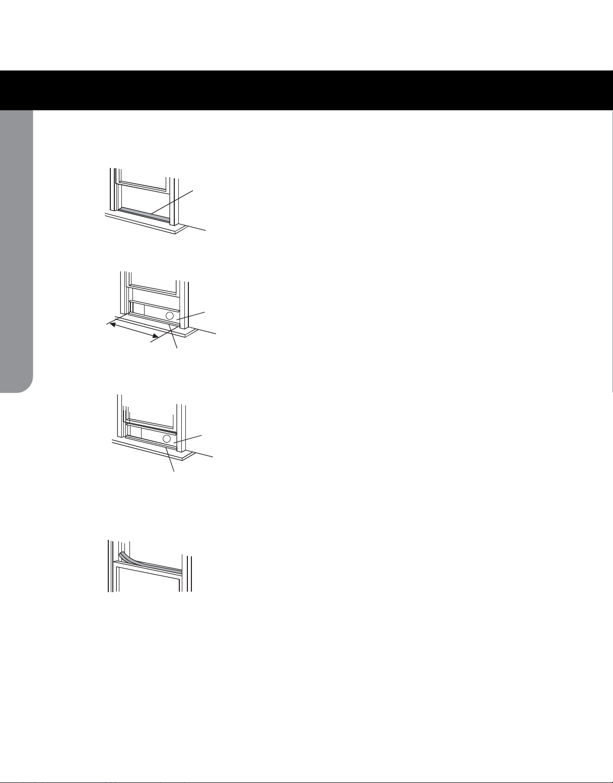
- Keep windows and doors closed for the best
dehumidifying effect.
- Do not put the duct to window.
- Press the "MODE" button until the "FAN "
indicator light comes on. The unit will operate
the auto fan speed automatically. The
temperature cannot be adjusted on fan mode.
- Press the "FAN" button on the remote control
- Do not put the duct to window.
This feature canbe activated from the
remote control ONLY.
NOTE: When more than one
error occurs,
the priority of the code display order is:
E4--E2--E1--P1.
motor operates at LOW speed.
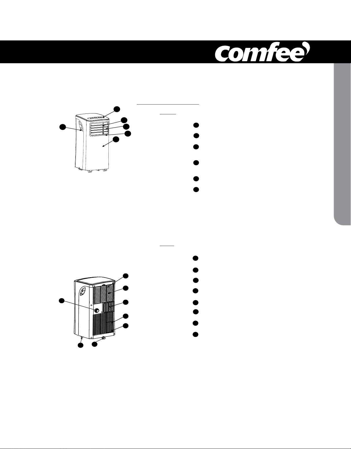
Sh ows th e s et t emperature in C
O
" "
" "
or
F an d the Aut o- timer settings.
O
UP( ) and DOWN( ) button
2
1MODE select button
ON-OFF button
4
Operating Instructions
COOL operation
DRY operation
FAN operation
SLEEP operation
3
LED Display
Selects the appropriate operating mode.
Each time you press the button, a mode
is selected in a sequence that alternates
between COOL, FAN and DRY. The mode
indicator light illuminates under the different
mode settings.
(Fig.3).
NOTE: On above modes, the unit operates the
auto fan speed automatically. You can set fan
speed only with the remote control, on COOL
and FAN modes.
to set the fan speed.
Used to adjust (increasing/decreasing)
O O
temperature settings in 1 C/2 F i ncrements
O O O O
in a range of 17 C/62 F to 30 C/88 F.
NOTE: The control can display temperature
in degrees Fahrenheit or degrees Celsius.
To convert from one to the other, press and
hold the Up and Down buttons at the same
time, for 3 seconds.
to set the fan speed.
When the SLEEP feature is selected, the set
temperature
O O O
will increase by 1 C/2 F(or 1 F)
in 30 minutes.The set temperature will then
increase by
O O O
another 1 C/2 F(or 1 F) after an
additional 30 minutes. This new temperature
will be maintained for 7 hours before it returns
to the initial temperature. This ends the Sleep
mode and the unit will continue to operate as
originally programmed.
Used to turn thepower off or on.
DRY mode. The room temperature may increase
over 30 C under sleep mode.
O
NOTE: This feature is unavailable under FAN or
Downloaded from www.Manualslib.com manuals search engine

8
Fig.4
Adjust
manually
Adjust
manually
If the unit turns off unexpectedly due to a
power outage or interruption, it will restart
automatically with its previous settings when
the power resumes.
After the unit has stopped, it cannot be restarted
in the first 3 minutes. This is to protect the unit.
Operation will automatically start after3 minutes.
Adjust the air flow direction manually
(Fig.4):
The louvers can be set to the desired position
manually.
Do not place any heavy objects or other loads
on the louvers; doing so will cause damage to
the unit.
Keep the louvers fully opened during
operation.
Other features
Auto-Restart
Wait 3 minutes before resuming operation
Air flow direction adjustment
OPERATING INS TRUCTIONS
model no. MPPH-06CRN1-BI0 | contact us: 1.866.646.4332
Downloaded from www.Manualslib.com manuals search engine

9
INSTALLATION INSTRUCTIONS
A:30cm (11.8")-100cm (39.4") B: 30cm (11.8")
INSTALLATION INSTRUCTIONS
LOCATION
Window Slider Kit Installation
Fig.5
bolt
Window slider kit
Horizontal
window
Horizontal
win do w
.)"6.62 ( mc5.76
Window Slider Kit
.)"6.62 ( mc5.76
Window Slider Kit
Fig.7a
Fig.6
Fig.7
The air conditioner should be placed on a firm
foundation to minimize noise and vibration. For
safe and secure positioning, place the unit on a
smooth, level flo or strong enough to support the unit.
The unit has casters for easier placement, but it should
only be rolled on smooth, flat surfaces. Use caution
when rolling on carpeted surfaces. Do not attempt to
roll the unit over objects.
The unit must be placed within reach of a properly
rated,grounded socket.
Never place any obstacles around the air inlet or
outlet of the unit.
of space
from the wall for efficient air-conditioning
(see Fig.5)
.
Your window slider kit has been designed to fit most
applications. However, it may be necessary for you to
improvise/modify some aspects of the installation
procedures for certain types of window. Please refer
to Fig. 6& Fig.7 for minimum and maximum window
openings.Window slider kit can be attached with a bolt
(see Fig.7a).
vertical
A
B
Allow at least
11.8" (30 cm) to 39.4" (100 cm)
hole A
The other piece of window slider kit would not be necessary.
Hole A
A in the
48.4''(123.0cm).
48.4''(123.0cm).
Downloaded from www.Manualslib.com manuals search engine

INSTALLATION INSTRUCTIONS
10
1. Cut the foam seal (adhesive type) to the proper
length and attach it to the windowsill. See Fig.8
2. Attach the window slider kit to the windowsill.
Adjust the length of the window slider kit according
to the width of window, shorten the adjustable window
kit if the width of window is less than 26.6 inches.
Open the window sash and place the window slider
kit on the windowsill. Fig.9.
3. Cut the foam seal (adhesive type) to the proper
length and attach it on the top of the window kit.
Se e Fig.10.
4. Close the window sash securely against the
window kit.
5. Cut the foam seal to an
appropriate length and seal the open gap
retuodnahsaswodniwdesolc potehtneewteb
window sash. See Fig.11.
Foam seal A
(adhesive type)
Window kit
windowsill
Foam seal
Fig. 8
Fig.9
Fi g.10
Fig.11
Window kit
windowsill
Installation in a double-hung sash
window
(non-adhesive type)
(non-adhesive type)
26.6"(67.5cm)~48.4"(123.0cm).
model no. MPPH-06CRN1-BI0 | contact us: 1.866.646.4332
Downloaded from www.Manualslib.com manuals search engine

INSTALLATION INSTRUCTIONS
11
Installation in a sliding sash window
1. Cut the foam seal A (adhesive type) to the proper
length and attach it to the window frame. See Fig.12.
2. Attach the window slider kit to the windowsill.
Adjust the length of the window slider kit according
to the width of window, shorten the adjustable window
kit if the width of window is less than 26.6 inches.
Open the window sash and place the window slider
kit on the windowsill. See Fig.13.
3. Cut the foam seal (adhesive type) to the proper
length and attach it on the top of the window kit.
See Fig.14.
4. Close the sliding sash securely against the window kit.
5. Cut the foam seal (non-adhesive type)
(non-adhesive type)
to an
appropriate length and seal the open gap
between the window sash and
outer window sash. See Fig.15.
Foam seal
Foam seal A
(adhesive type)
Window
panel
Fig.12
Fig. 13
Fig.14
Fig.15
closed side
26.6"(67.5cm)~48.4"(123.0cm).
Downloaded from www.Manualslib.com manuals search engine

12
Exhaust hose installation:
The exhaust hose and adaptor must be installed or removed
in accordance with the installation of the unit.
The duct can b e com pressed or extended moderately
accordin g to the installation requirements, but it is
preferable to ke ep the duct l ength to a minimum.
IMPORTANT:
DO NOT OVER
Fig.17
Note:
Cover thehole f or the adaptor cap when not in use.
Fig.16
COOL or AUTO mode
FAN
DEHUMIDIFY
or mode
Install
Rem ove
Fig
.
18
1. Install the window exhaust adaptor B onto the exhaust
hose as shown in Fig.1 Refer to the previous
pages for window kit installation.
2. Push the exhaust hose into the airoutlet opening along
the arrow direction(See Fig.1
6.
7).
18)
- BEND THE DUCT (SEE Fig.
INSTALLATION INSTRUCTIONS
model no. MPPH-06CRN1-BI0 | contact us: 1.866.646.4332
Downloaded from www.Manualslib.com manuals search engine

13
-
When the water level
in
the bottom tray reaches
a predetermined level,
Carefully move the unit to a drain location,
remove the bottom drain plug and let the
water drain away (Fig.2
1
). Reinstall the bottom
drain plug and restart the machine until the P1
symbol disappears. If the error repeats, call for
service.
" "
the unit beeps 8 times and
the digital display area shows P1 . At this time
the air conditioning/dehumidification process will
immediately stop. However, the fan motor will
continue to operate (this is normal).
" "
Fig.19
Fig.20
Fig.21
Water drainage:
R emove the
drain plug
Continuo us
drain hos e
Bottom dra in plug
-
plug from the back of the unit. You may also
connect a 3/4" (1.9cm) garden hose (sold
separately) onto the 5/8" (1.58cm) drain
connector on the unit. For models without a
drain connector, just attach the drain hose to
the hole. Place the open end of the hose directly
over the drain area in your basement floor.
Please refer to Fig.19 & 20.
I n dehumidifying mode,remove the drain
INSTALLATION INSTRUCTIONS
Downloaded from www.Manualslib.com manuals search engine

14
Fig.22
1) Be sure to unplug the unit before cleaning or servicing.
2) Do not use gasoline, thinner or other chemicals to clean
the unit.
IMPORTANT:
1. Air filter
- Clean the air filter at least once every two weeks to prevent
- Removal
Take the air filter out along the arrow direction (Fig.22).
- Cleaning
Wash the air filter by immersing it gently in warm water
OO
(about 40 C/104 F) with a neutral detergent. Rinse the filter
and dry it in a shady place.
- Mounting
Install the air filter after cleaning (see Fig.23).
2. Unit enclosure
- Remove the rubber plug at the back of the unit and attach
a hose to drain outlet. Place the open end of the hose
directly over the drain area in your basement floor
(See Fig.19 & 20).
- Remove the plug from the bottom drain outlet, all the water
in the bottom tray will drain out (See Fig.21).
- Keep the appliance running on FAN mode for half a day in
a warm room to dry the appliance inside and prevent mold.
- Stop the appliance and unplug it, wrap the cord and
bundle it with the tape. Remove batteries from
the remote control.
- Clean the air filter and reinstall it.
NOTE:
Fig.23
Air filter
(install)
Air filter
(take out)
CARE AND MAINTENANCE
3) Do not wash the unit directly under a tap or using a hose.
It may cause electrical shock.
4) If the power cord is damaged, it should be repaired/replaced
by the manufacturer or its authorized agent.
dust from affecting fan operation.
- Use a lint-free cloth soaked with neutral detergent to clean
the unit enclosure. Dry enclosure with a clean cloth.
3. If the unit will not be used for a long time
The grill and the air filter are connected but can be
separated.
CARE AND MAINTENANCE
model no. MPPH-06CRN1-BI0 | contact us: 1.866.646.4332
Downloaded from www.Manualslib.com manuals search engine

15
T R O U B L E S H OOTI N G
1. Uni t does not
start when
pres sing on /o f f
button
TROUB LES POSSIBLE CAUSES SUGGEST REMEDIES
Reset the temperature.
Make sure all the windows and
doors are closed.
Remove the heat sources if possible.
Connect the duct and make
sure it can function properly.
Decrease the set temperature.
Clean the air filter.
- Room temperature is lower than
the set temperature.(Cooling mode)
- The windows or doors in the room
are not closed.
- There are heat sources inside the
room.
- Exhaus t air duct is not connected or
is blocked.
- Temperature setting is too high.
- Air filter is blocked by dust.
2. Air is not cool enough
Place the unit on a flat, level
floor if possible.
This sound is normal.
- The floor is not level or not flat
enough.
- The sound comes from the
refrigerant flowing inside the
air conditioner.
4. Noise or vibra ti on
5. Gu rgling sou nd
Switch on again after the unit
has c ool down.
-Caused by the unit's overheating
protection function.
When the
t em perat ure at th e air ou t le t
e x c eeds 70 C/158 F, the unit
wi ll sto p .
O O
6. Power shut off in
heating mode
- P1 appears in the display window Drain the water in the bottom tray.
TROUBLESHOOTING TIPS
Downloaded from www.Manualslib.com manuals search engine

16
Model
Transmission Distance
Lowest Voltage of
CPU Emitting Signal
Rated Voltage
8m
2.0V
Environment
Specification
。 。 O O
-5 C 60 C(-41 F~140 F)
RG09E/BGCE
3.0V(Dry batteries R03/LR03×2)
CLOCK
C
ON
OFF
SET TE MP.
FAN SPEED
AUTO
F
~
REMOTE CONTROL INSTRUCTIO
model no. MPPH-06CRN1-BI0 | contact us: 1.866.646.4332
Downloaded from www.Manualslib.com manuals search engine

17
Features of remote control
1
ON/OFF Button: Push this button to start operation, push
the button again to stop operation.
2
MODE Select Button: Each time you push the button, a mode
is selected in a sequence that goes from AUTO, COOL, DRY
and FAN, as the following figure indicates:
AUTO
COOL
DRY
FAN
1
2
3
4
5
6
7
8
9
10
11
CLOCK
C
ON
OFF
SET TEMP.
FAN SPEED
AUTO
F
3
TEMP/TIME Button : Push the button to increase the
indoor temperature setting or to adjust the TIMER in a clockwise
direction. Push the button to decrease the indoor
REMOTE CONTROL INSTRUCTIO
Downloaded from www.Manualslib.com manuals search engine

18
Features of remote control(continued)
RESET Button: When you press the recessed RESET button,
all current settings are cancelled and the control will return to
the initial settings.
FAN Button: Used to select the Fan Speed in four steps-
AUTO、LOW 、MED(some models without) or HIGH. Each
time the button is pressed, the fan speed mode is shifted.
temperature setting or to adjust the TIMER in a counter-clockwise
direction.
NOTE: Press and hold and buttons together for 3 seconds
will alternate the temperature display between the C & F scale.
TIMER Button: This button is used to preset the time ON
(start to operate) and the time OFF (turn off the operation).
LOCK Button: When you press the LOCK button, all current
settings are locked in and the remote controller does not accept
any operation except that of the LOCK. Press again to cancel
the LOCK mode.
CANCEL Button:
(a). If the TIMER ON, TIMER ON OFF or TIMER OFF ON
feature has been set, press the CANCEL button will override
the TIMER program and turn off the unit as well.
(b). If only set TIMER OFF feature, press the CANCEL button
will cancel the timer off setting and turn on the unit (when
the unit is off).
(c). If no TIMER feature has been set, press the CANCEL button,
and nothing will happen.
CLOCK Button: Use to set the time.
LED Button: Press this button to clear the digit display in the
air conditioner, press it again to activate it .
SLEEP Button: In SLEEP mode,
Active/Disable sleep function. It can maintain the most
comfortable temperature and save energy. This function is
available on COOL or AUTO mode only. For the detail,
see Sleep operation in USER S MANUAL.
,,,
NOTE:
be cancelled if MODE, FAN SPEED or ON/OFF button is
pressed.
While the unit is running under SLEEP mode, it would
,,,,
,,
6
5
7
9
8
10
11
4
REMOTE CONTROL INSTRUCTIO
model no. MPPH-06CRN1-BI0 | contact us: 1.866.646.4332
Downloaded from www.Manualslib.com manuals search engine

19
CLOCK
C
ON
OFF
SET TEMP.
FAN SPEED
Indicators on remote controller
Transmission Indicator
Temp. display
Time display
Fan speed display
Sleep Display
Mode display
ON/OFF display
This transmission indicator lights when
remote controller transmits signals to the
indoor unit.
Displays the current operation mode. Including
AUTO( ), COOL( ), DRY( ) , FAN
ONLY
( )and back to AUTO( ).
。
Displays the temperature setting (17 C/62 F
to 30 C/86 F)when you set the operating
mode to FAN ONLY, no temperature setting is
displayed.
Displayed by pressing the ON/OFF button.
Press the ON/OFF button again to remove.
The clock time is indicated only when no
AUTO-ON/OFF timer is set. When AUTO-
TIMER feature is operating, it displays the
AUTO-ON/OFF time. To check the current
time, press the CLOCK button, and the time
will display.
Indicate Timer on/off time(0 24 hours)
or clock time.
Displays the selected fan speed, AUTO
and three fan speed levels " " (LOW)
" " (MED) " " (HIGH)
can be indicated. Displays AUTO when the
operating mode is either AUTO or DRY.
Displayed by pressing the SLEEP button.
Press the SLEEP button again to remove.
Note:
All displays on the remote controller are
shown for illustration purposes only.
AUTO
F
AUTO
AUTO
Lock Display
Displayed by pressing the LOCK button.
Press the LOCK button again to remove.
~
Note: Some models have no MED Fan
speed selection.
REMOTE CONTROL INSTRUCTIO
Downloaded from www.Manualslib.com manuals search engine

20
Keep the remote controller where its
signals can reach the receiver of the
unit (a distance of 8m is allowed).
When you select the timer operation, the
remote controller automatically transmits
a signal to the indoor unit at the specified
time.
If you keep the remote controller in a
position that hinders proper signal
transmission, a time lag of up to 15
minutes may occur.
Location of the remote controller.
.
.
8m
CAUTIONS
The air conditioner will not operate if curtains, doors or other materials
block the signals from the remote controller to the indoor unit.
Prevent any liquid from falling into the remote controller. Do not expose
the remote controller to direct sunlight or heat.
If the infrared signal receiver on the indoor unit is exposed to direct
sunlight, the air conditioner may not function properly. Use curtains to
prevent the sunlight from falling on the receiver.
If other electrical appliances react to the remote controller. either move
these appliances or consult your local dealer.
.
.
The remote controller uses two
dry batteries (R03/LR03X2)
(1) Slide the cover of the battery
compartment off according to the
arrow direction, then replace the
old batteries with new ones.
(2) Insert the new batteries making
sure that the(+) and (-) of battery
are installed correctly.
(3) Reattach the cover by sliding it
back into position.
After replacing batteries, set the
remote controller clock.
Replacing batteries
.
.
.
Handling the remote controller
Do not recharge batteries or dispose of them in fire.
Battery disposal-please dispose the used battery per municipal or provincial law.
protect the environment
containers to
REMOTE CONTROL INSTRUCTIO
model no. MPPH-06CRN1-BI0 | contact us: 1.866.646.4332
Downloaded from www.Manualslib.com manuals search engine
This manual suits for next models
1
Table of contents
Other Comfee Air Conditioner manuals

Comfee
Comfee GLACE 8C User manual

Comfee
Comfee PDA-12 Series User manual

Comfee
Comfee SOGNIDORO-09E User manual

Comfee
Comfee CP05S3WBA1RCM User manual

Comfee
Comfee Libeccio CF-XT09A IU Repair manual

Comfee
Comfee MPPH-07CRN7 User manual

Comfee
Comfee AMBRA 6C User manual

Comfee
Comfee MPPDB-12HRN7-QB6G1 User manual

Comfee
Comfee MPPH-06CRN1-BI0 User manual

Comfee
Comfee Eco Friendly Pro User manual