Comfort Bilt HP61 User manual

H P 6 1 P E L L E T S T O V E
O W N E R ' S M A N U A L
Please read this entire manual before installation and use of this fuel-burning pellet room heater, and save for future reference.
Failure to follow these instructions could result in property damage, bodily injury, or even death.
Contact local building or fire officials about restrictions and installation inspection requirements in your area.
WARNING!
Building Quality
Building Quality
Building Quality
Comforts
Comforts
Comforts


DANGER! HOT SURFACES
Glass and other surfaces are hot during operation and cool down.
Hot glass will cause burns.
DANGER! Indicates a hazardous situation which, if not avoided, will result in death or serious injury.
WARNING! Indicates a hazardous situation which, if not avoided, could result in death or serious injury.
CAUTION! Indicates a hazardous situation which, if not avoided, could result in minor or moderate injury.
NOTICE: Indicates practices which may cause damage to the stove or to property.
Pro Tip: Indicates additional information to help you better understand your stove and optimize its
performance.
Safety Alert Key: It is important to pay attention to alerts you will see throughout this manual to ensure your
safety.
Install or operate damaged stove.
Modify Stove.
Install other than as instructed by the manufacturer.
Operate the stove without fully assembling all components.
Over Fire (burning at higher temperatures than recommended, causing permanent
damage to the stove.)
Install any components not approved by the manufacturer.
Install parts or components not listed or approved.
Disable safety switches.
Do not touch glass until it is cooled.
NEVER allow children to touch glass or door.
Keep children away; if you expect that children may come into contact with the stove, we
recommend a barrier such as a decorative screen.
CAREFULLY SUPERVISE children in the same room as the stove.
Alert children and adults to hazards of high temperatures.
NOTICE: FIRE RISK
SMG Hearth and Home / ComfortBilt disclaims any responsibilty, and the warranty and agency listing
will be voided by the below actions.
This wood heater needs periodic inspection and repair for proper operation.
It is against federal regulations to operate this wood heater in a manner inconsistent with operating
instructions in this manual.
Keep clothing, furniture, draperies, and other flammable materials away.
High temperatures may ignite clothing or other flammable materials.
This product, and the fuels used to operate is (wood), and the products of combustion
of such fuels, can expose you to chemicals including carbon black, which is known to
the State of California to cause cancer, and carbon monoxide, which is known to the
State of California to cause birth defects and other reproductive harm.
For more information go to www.P65warnings.ca.gov
3
DO NOT:
WARNING!
comfortbilt.net
Stay Safe!

This stove should NOT be used as the only source of heat in the home. Power outages and periodic
maintenance will result in a total loss of heat.
Contact local building or fire officials regarding restrictions and installation inspection requirements for
your area.
Contact your local authority (Municipal building department, Fire department, Fire prevention bureau,
etc...) to determine the need for a permit.
Keep combustible materials (such as grass, leaves, etc...) at least 3 feet away from the flue outlet on the
outside of the building.
Installation and repair of this pellet stove should be done by a qualified service person. The appliance
should be inspected before use, and at least annually by a qualified service person. It is imperative that
the control compartments, fire box, and circulating air passageways of the stove be kept clean.
CAUTION!
During a power outage, the stove will shut down safely. Do not open the main door or ash pan door.
During a power failure, the exhaust fan will not run. Keeping the doors sealed will allow the exhaust
vent to draft out naturally. When the power is restored, the stove will not restart. If the exhaust
temperature is still 126° F (52° C) when power is restored, the exhaust and convection fans will
continue to run until the stove cools.
Over Fire Protection: If the stove is being over fired or burning too hot, the high limit switches will
automatically shut down the stove to avoid damage to other components. If the temperature on the
hopper reaches 197° F (92° C), the auger will automatically stop and the stove will shut down. The
exhaust fan will continue to run until the proof of fire switch cools. Allow the stove to cool before
attempting to re-ignite.
NOTICE!
Install at least one smoke detector on each floor of your home to ensure your safety. They
should be located away from the stove, and close to the sleeping areas.
You should have separate CO monitors for areas near the stove
4comfortbilt.net
CAUTION!
If the electrical power fails at any time when the stove is hot, keep all stove doors closed.
This will limit the amount of smoke in the space.
Never shut the stove down (while running) by unplugging it from the power source.
Never shut the stove down (while running) by switching off the main power switch on the
rear of the stove.
WARNING!
This stove has a manufacturer set minimum low burn rate that must not be altered. It is against federal
regulations to alter this setting or otherwise operate this stove in a manner inconsistent with the
operating instructions within this manual. If the unit is modified, it will no longer be compliant with the
EPA regulations.
Stay Safe!

5comfortbilt.net
Fuel Guide
Getting Ready
Control Panel Operation
Control Panel Display
Pre-Ignition Checklist
Operational Modes
Starting Your Stove
Settings
Pre-Installation
Floor Protection
Clearances to Combustibles
Vent Termination Clearances
Venting
Installation Examples
Troubleshooting Video
Total Power Loss
Low Temperature Alert
High Temperature Alert
Failure to Ignite
Lazy Burn / Pellet Buildup
Safety Key
Additional Warnings
Getting Familiar with Your Stove
What's Included
Maintenance & Cleaning Video
Side Panel Access
BTU & Efficiency Specifications
Electrical Rating
Glass Specifications
Warranty Coverage and Limitations
Table of Contents
Getting Started.........................................................................6
Installation...............................................................................8
Operation...................................................................................16
Maintenance.............................................................................28
Troubleshooting.....................................................................32
Certifications..........................................................................34

Room Temperature
Sensor
Igniter
(Behind Burn Pot)
Hopper Lid Switch
(Beneath Hopper Fill Lid)
Magnetic Side Panels
Serial # and
Safety Placard
Main Power Switch
(Backup Fuse Included)
Front Door Latch/Handle
(Behind Side Panel)
6comfortbilt.net
Getting Started
Getting Familiar with your Stove
Removable Ash Pan
Drawer
Control Panel
Pellet Feed Chute
Burn Pot
Heat Exchange Tubes
Heat Tube
Cleaner/Scraper
Inside the Stove Body:
-Auger System
-Circuit Board
-Combustion Blower
-Convection Blower
-Vacuum Switch
-POF Sensors
-Air Intake Damper
Exhaust Port
Air Intake Port
Data Cable
Glass Airwash Damper
(Behind Front Door)
Adjustable Leveling
Feet
Getting Started

Do NOT install damaged, incomplete, or
substitute components.
Inspect stove and components for damage.
Damaged parts may impair safe operation.
Report damaged parts to dealer or manufacturer.
Safety Equipment (Recommended for all installation and maintenance steps)
Pellet Vent Pipe
Must be an approved 3" or 4" diameter Type "L" or "PL" vent. Use 4" diameter vent if flue height is over 12 ft.
or if installation is over 5,000ft above sea level.
7comfortbilt.net
What's Included
Owner's Manual
Power Cord Control Panel & Bracket
WARNING! CAUTION!
Risk of cuts, abrasions, or flying
debris.
Wear protective gloves and safety
glasses during installation.
Metal edges may be sharp.
What You May Need
High temperature silicone (500°F+)
Screwdriver
Allen wrench set
Tools & Supplies
Tape measure
Framing square
Reciprocating saw
Electric drill & bits
Caulking gun
Level
Plumb Line
Stud Finder
Utility knife
Pliers
Flashlight
Hammer
WARNING!
NO OTHER vent component may be used. Substitute or damaged vent components may
impair safe operation.
Floor Protection
Non-combustible material
(such as a hearth pad) is
required underneath your
stove.
Surge Protector
Protect the electrical
components of your stove by
using a surge protector.
Pellet Fuel
Use only wood pellets in your
stove. For best performance,
use premium, low-ash pellets
(<1%), a length of 1" or less,
and avoid excess dust and
broken pieces in the bottom of
the bag.
Remote Control
1 Year Warranty
Data Cable
Online Guides and
Videos
Getting Started
Fire Risk:
Safety glasses Close-toed shoesGloves
Getting Started

Remove cardboard lid, outer box sleeve, and packing foam.
Inspect for any shipping damage. (Preferably before delivery
team leaves)
Unscrew the mounting L brackets that secure the rear of the
stove to the pallet. (4mm Allen)
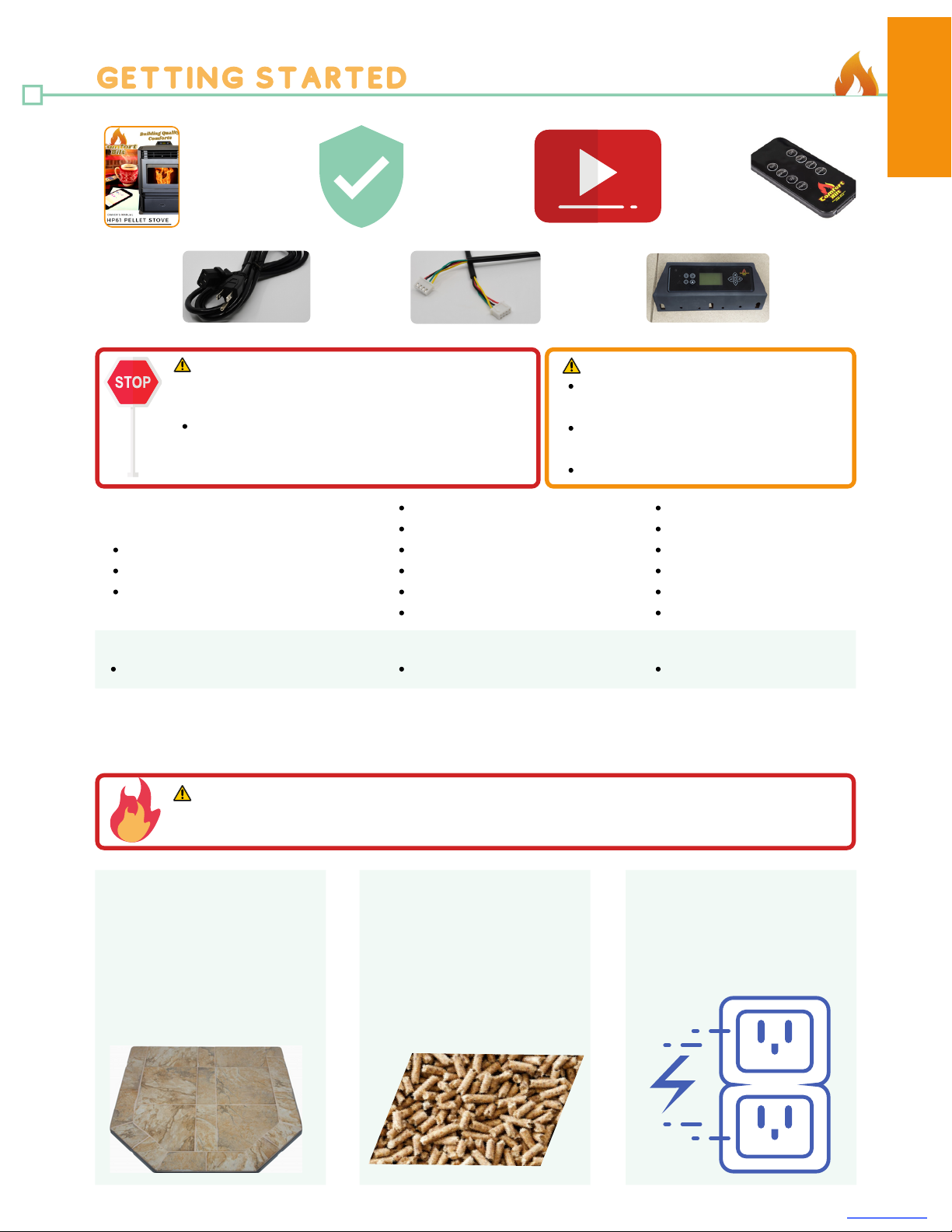
Open hopper lid and remove control panel, power cord, remote
control, and all literature and packing material from the hopper.
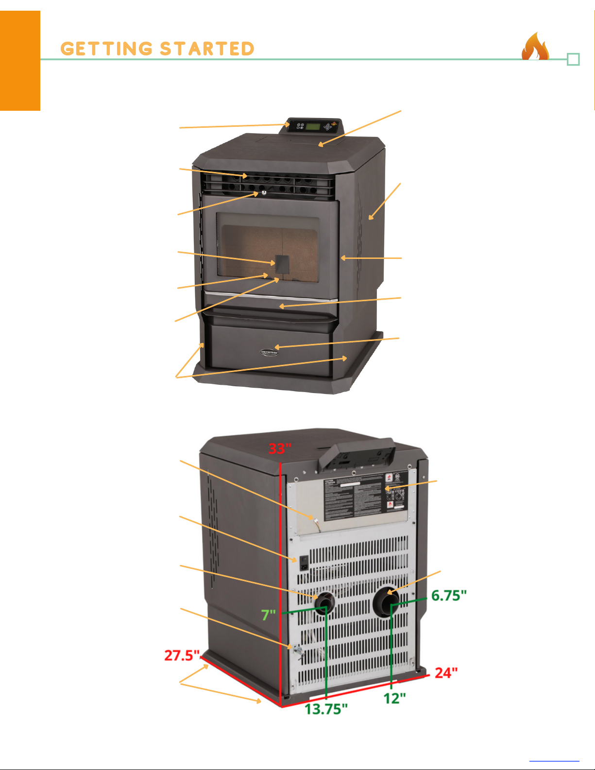
Open the front door via the latch on the right side behind the
magnetic side panel (see picture) and remove cardboard
packing material from the firebox chamber.
Remove any tape or adhesive on the outside of the glass.
Unpacking:
Remove all four Phillips mounting screws along the top rear of
the stove where you wish to mount the controller bracket.
Line up the holes in the back to the mounting bracket and
secure in place. (Note: Universal mounting brackets are used,
so only the far left and two right screws align. This is normal,
and will still secure the panel to the stove)
Find the data cable line at the rear of the stove, and plug it
snugly into the back of the control panel.
Mounting the Control Panel:
1.
2.
3.
8comfortbilt.net
Installation
Pre-Installation
The universal mounting bracket will also allow for the control
panel to be mounted to the side farthest from the exhaust port
for specific vertical venting scenarios. (The two left and the far
right screws are used in this case).
Installation MUST comply with local, regional, state and national codes and regulations.
Consult insurance carrier, local building inspector, fire officials, or authorities having jurisdiction over
restrictions, installation inspection and permits.
Pro Tip: It is recommended that your pellet vent pipe be installed and serviced by a professional installer.
Placement:
Where you place your stove can significantly affect its performance and safety.
Sketch out a plan for installing the stove, including dimensions, before permanent placement. When
determining the location for the stove, wall stud location is critical. You may need to adjust the location of the
stove to avoid encountering a wall stud. Before placing the pellet stove, connect the vent to allow for minimum
clearances to combustible walls.
WARNING!
Asphyxiation Risk:
DO NOT INSTALL IN A SLEEPING ROOM.
Stove consumes oxygen in the room.
Front Door Latch
Control Panel Mounting
Data Wire Connection
Side Mounting
Installation

Notice: Be careful to protect the bottom of the stove and floor surfaces when moving the stove. Bottom
edges of the stove may be sharp and can scratch surfaces.
Notice: Clearances may only be reduced by means approved by the regulatory authority having jurisdiction.
9comfortbilt.net
Installation
Floor Protection
It is necessary to install Ember Protection: a type 1 floor protector for this stove.
The floor protector must be non-combustible material, extending beneath the stove with a minimum of 6
inches (152mm) in front of the glass, and 6 inches (152mm) to both sides of the stove.
The stove must be installed on a noncombustible floor, with proper floor protection, or on a masonry hearth.
When a clean out T-vent is installed on the inside of a home, the floor protector must extend 2 inches beyond
the rear of the T-vent.
When stove is vented straight through the wall and the clean out T-vent is on the exterior of the home, the
minimum clearance is 2 inches from the back of the stove to the wall.
Non-combustible floor protection extending beneath the flue pipe is required with horizontal venting or
under the top vent adapter with vertical installation.
Non-combustible floor protection must extend 2 inches (51mm) beneath the flue pipe when installed
horizontal venting or under the top vent with vertical installation.
6"
6"
6"6"6"
6"
2"
2"
Installation

10 comfortbilt.net
Installation
5"
5"
5"
5"
2"
7"
7"
2"
Clearances to Combustibles
Confirm required clearances to combustibles (Combustibles include wood, drywall, etc...)
2"
Notice: When interior vent is installed vertically, the clearance to the back wall is determined by the vent
size used. Install vent at clearance specified by the vent manufacturer. Take into consideration any upward
turning elbows or tees.
Back walls to Stove rear corners: 5" (13cm)
Back wall to Stove back: 2" (5cm)
Side wall to Stove: 7" (18cm)
Horizontal installation
Back walls to Stove rear corners: 5" (13cm)
Back wall to pellet pipe: 2" (5cm)
Side wall to pellet pipe: 2" (5cm)
Side wall to Stove: 7" (18cm)
Vertical installation
Installation

11 comfortbilt.net
Installation
Vent Termination Clearances
Must have an approved cap (to prevent water from entering) or a 45 degree downturn with rodent screen.
If the termination is located on a windy side of the house, we suggest using an approved house shield to
prevent soot from building up on the side of the house.
A vent must not be located where it may become plugged by snow or other material.
The stove vent must terminate on the outside of the building. Horizontal terminations must extend a minimum
of 12" from the wall. Vertical terminations must protrude a minimum of 24" from the roof surface.
In addition, all clearances listed below must be met.
A: Minimum 48" clearance below or beside any door or window that opens. (This clearance may be reduced to
18" if using outside air). We recommend the door or window be kept closed during operation. Minimum 12"
clearance below or beside any window that does not open.
B: Minimum 12" clearance above any door or window that opens.
C: Minimum 24" clearance from any adjacent building.
D: Minimum 7' clearance above any grade, when adjacent to public walkways.
E: Minimum 24" clearance above any grass, plants, or other combustible materials.
F: Minimum 36" clearance from any forced air intake of another appliance.
G: Minimum 24" clearance below eaves or overhangs.
H: Minimum 12" clearance horizontally from combustible wall.
X: Must be a minimum of 24" above the roof.
NOTICE:
In any location that will allow flue gasses or soot to enter or stain the building.
In any location which could create a nuisance or hazard.
In any enclosed or semi enclosed area such as a carport, garage, attic, crawl space, under a sun deck
or porch, or narrow walkway.
Closely fenced area, or any location that can build up a concentration of fumes such as a stairwell,
covered breezeway, etc...
Do NOT terminate vent:
It is recommended that at least 3 ft of vertical pipe be installed when the stove is vented directly
through a wall - this will create a natural draft, which will help prevent the possibility of smoke or odor
venting into the home during a power outage.
Do NOT terminate vent below air inlet.
Installation

The pellet venting pipe (also known as L vent) is constructed of two layers with
air space between the layers. This air space acts as an insulator and reduces
the outside surface temperature of pipe to allow a clearance to combustibles.
A cap must be used at the termination of type L vent chimneys.
For elevations above 5,000 feet above sea level, 4" venting is recommended.
Some venting manufacturers offer pellet stove adapters for their venting for
easier installation.
Seal all pipe joints using high-temp silicone (500°+)
Install pellet venting through wall and connect vent/pipe to stove
Mark and cut wall for venting penetration on exterior wall (if needed).
Install wall thimble (sold separately) per manufacturer specifications.
Install venting.
Use a sealant (such as silicone) to create an effective vapor barrier at the location where the chimney or
other component penetrates the exterior of the structure.
1.
2.
3.
4.
Take appropriate precautions to locate utilities within the wall and avoid contact.
Pro Tip: Installing a clean-out “T” (sold separately), when venting vertically, can save time during
cleaning, and is recommended to aid in the periodic cleaning and maintenance.
Secure exhaust venting system to the Stove per the pipe manufacturer’s instructions.
Install termination cap.
Confirm all required Stove clearances to combustibles.
The vent must have a support bracket every 5' of pellet vent when on the exterior of the structure.
12 comfortbilt.net
Installation
Venting
CAUTION!
Do NOT connect to any air distribution duct or system.
Do NOT install a flue damper in the exhaust venting
system of this stove.
Do NOT Connect this stove to a chimney flue serving
another appliance.
The structural integrity of the manufactured home
floor, wall, and ceiling/roof must be maintained.
Adding bends in the exhaust path restricts air flow,
reduces performance, and provides a collection point for
ash deposits requiring more frequent cleaning.
CAUTION!
Required: Only use 3" or 4" type "L" or "PL" pellet pipe.
Secure 3" appliance adapter to the exhaust port using a
high temperature sealant (such as RTV silicone)
Improper drafting.
Smoke may seep into the house.
Excessive sooting.
Ensure that your stove venting terminates above the stove or the follow may occur:
Install at least one smoke detector on each floor of your home to ensure your safety.
They should be located away from the stove, and close to the sleeping areas.
You should have separate CO monitors for areas near the stove
CAUTION!
Installation

Connection from the intake pipe (2" diameter pipe in rear of stove) to the outside of the house is
REQUIRED for mobile home installation. It is recommended in tightly sealed homes with exhaust fans
such as kitchen or bathroom fans, or in basement installations. This will eliminate poor performance due to
negative pressure.
Only noncombustible pipe 2" (or greater) in diameter is approved for outside air connections (Straight or
flexible). PVC pipe is NOT approved and should NEVER be connected to the stove.
If the air inlet is connected to the outside, it MUST be terminated with a vertical 90° bend down, or with a
wind hood. Failure to do so could result in a burn-back if high winds blow directly into the air inlet during a
power outage.
Blockages, excessive length (more than 8 ft.), or excessive bends in the air intake pipe could lead to
starvation of combustible air to the stove.
Outside Air Intake (available separately)
The stove must be permanently attached to the floor.
Stove must have an outside air source.
Stove must be electrically grounded to the steel chassis of the mobile home, unless grounded or GFCI
power outlets are provided.
All vertical chimney vents must have wall supports.
All exhaust systems must have a spark arrestor.
Check with local building officials to see if other codes may apply.
Structural integrity of the floor, wall and ceiling/roof must be maintained.
Mobile Home Installation
Installation in a mobile home should be in accordance with the manufactured home and safety standard
(HUD), CFR 3280, Part 24. This stove must be vented to the outside. In addition to the standard installation
instructions, the following requirements are mandatory for installation in a mobile home:
Do not install flue damper in the exhaust venting system of this unit.
Use an approved wall thimble when passing the vent through walls. Use a ceiling support/fire stop spacer
when passing the vent through ceilings. (Make sure to maintain minimum clearances to combustibles).
If using more than one T-vent or exceeding 180° of elbows, the use of 4" venting pipe is recommended.
The vent must have a support bracket every 5' of pellet vent when on the exterior of the structure.
Horizontal sections of vent pipe should have a 1/4 inch rise per foot. We recommend using the shortest
venting and fewest elbows possible when venting horizontal.
Horizontal vent runs can accumulate ash and will need to be cleaned more often. Try to keep them as
short as possible.
Contact local building or fire officials about restrictions and installation inspection requirements in your
area.
Contact your local authority (such as municipal building department, fire department, fire prevention
bureau, etc.) to determine the need for a permit.
13 comfortbilt.net
Installation
Venting (Continued)
Pro Tip: Use the bottom adjustable leveling feet for vertical movement of the stove up to 3/4". This will
allow for micro adjustments when precise venting alignment is needed.
Notice: The operation of exhaust fans, such as bathroom and attic fans, could create a negative pressure
in the room, causing the stove to be starved of combustible air. Be sure to provide adequate ventilation in
the room the pellet stove is located. If not, the vacuum pressure switch may shut off the operation of the
pellet stove.
Installation

Exhaust cap
Exhaust cap
Exhaust cap
14 comfortbilt.net
Installation
Clean-out Tee
Clean-out Tee
Wall Thimble
Wall Thimble
90° Elbow 90° Elbow
Wall Wall
Wall strap
Floor Protection Floor Protection
Simple Vertical Installation (preferred)
Wall Thimble
Wall
Floor Protection
Appliance Adapter Appliance Adapter
Appliance Adapter
Simple Horizontal Installation
Air Intake
Air Intake
Installation

16 comfortbilt.net
Operation
Fuel Guide
Wood pellets are generally produced out of wood waste such as sawdust and shavings. The raw material
is dried, mechanically fractioned to size and extruded into pellets under high pressure.
This pellet stove is designed and approved to burn wood pellets, that comply with pellet fuels industry
standards. Minimum of 40 lbs. density per cubic foot, 1/4" to 5/16" in diameter, with a maximum length of
1", and less than 1% ash.
The performance of your pellet stove is greatly affected by the type and quality of the wood pellets you
use. As the heat output of various quality wood pellets differ, so too will the performance and heat output
of the pellet stove.
We recommend trying various brands and types before purchasing single-ton or muli-ton lots to ensure
satisfaction. A 5-bag sample of pellets will give a good indication of what to expect from a certain
brand/type.
Wood pellets need to be protected from direct exposure to moisture. Water, from sources such as
condensation and humidity, causes pellets to expand and break down into unusable fuel.
Store fuel in dry location, not within clearances to combustibles of your stove.
It is important to select and use only pellets that are dry and free from dirt and debris. Dirty fuel will
adversely affect the operation and performance of the unit, and can void the warranty. The Pellet Fuel
Institute (PFI) has established standards for wood pellet manufacturers. Only use pellets that meet or
exceed PFI standards for premium fuels.
Depending on the source material, pellets may have differing ash contents.
Fuel Material and Storage
The type of fuel you are burning will dictate how often you have to clean your fire pot.
If the fuel you are burning has a high dirt or ash content, it may be necessary to clean the burn pot more
than once per day.
Poor quality fuel will cause clinkers to form in the burn pot. Clinkers are formed when non-combustible
impurities are super heated and become glass-like.
Pro Tip: We recommend using Pellet Fuels Institute (PFI) certified pellet fuel with this stove.
Notice: Tested and approved for wood pellet fuel only. Burning any other type of fuel voids warranty.
(Cord wood, wood chips, corn, shells, cherry pits, etc...)
Hardwoods with a high mineral content.
Fuel that contains bark and other impurities.
Standard grade pellets.
Higher Ash Content Material:
Most softwoods.
Fuels with low mineral or impurity content.
Most premium grade pellets.
Lower Ash Content Material
Garbage, Lawn clippings or yard waste, Materials containing rubber, including tires, Materials
containing plastic, Waste petroleum products, paints or paint thinners, or asphalt products,
Materials containing asbestos, Construction or demolition debris, Railroad ties, or pressure-treated
wood, Manure or animal remains, or Paper products, cardboard, plywood, or particleboard
Do Not Burn:
Burning these materials may result in the release of toxic fumes or render the heater ineffective and
cause smoke.
WARNING!
Operation

17 comfortbilt.net
Operation
Getting Ready
Combustion blower will turn on. (Panel will display "Igniting")
Igniter will heat up.
Auger system will deliver pellets into the burn pot. (Smoke may occur during ignition but will evacuate once
the flame appears in the burn pot.)
Convection blower will turn on once the stove heats up. (Panel will display "Heating")
Combustion and convection blowers will continue to run even after your stove has been shut down. (Panel
will display "Fire off" or "Cooling")
What to Expect
Odors and vapors are released during initial startup after purchase, and may persist for several days.
Burning your stove on a higher level will speed the curing process. Open windows or doors for air
circulation until curing/burn off is complete, or perform a "pre-burn" outdoors.
During startup and operation, the stove's front door must be closed.
Priming is only required the first time the stove is lit, or after a "Low Temperature" fault due to low pellets
in the hopper. (see Pre-ignition checklist)
Pro Tip
Your stove utilizes a vertical auger fuel feed system that is operated by a microprocessor controlled digital
circuit board. The digital circuit board allows the vertical auger fuel system to run in a timer based, non-
continuous cycle. This cycling allows the auger to run for a predetermined amount of time. The auger
pushes pellets up a chute located in the hopper. The pellets will then turn and fall through another chute
into the burn pot.
Your stove is equipped with an automatic ignition system that should ignite the fuel within 5 minutes of
displaying "Igniting".
As pellets fill the burn pot and ignite, outside air is drawn through the fuel and heated during the
combustion process which is then pulled across the heat exchange tubes by the exhaust motor.
As the stove reaches operating temperature, the room air is then circulated through the heat exchange
tubes by a room air blower (convection blower), distributing warm air into the room.
The amount of heat that is produced by the stove is proportional to the rate of fuel that is burned.
Because a forced draft pressure is required for the combustion process inside the stove, it is extremely
important that the exhaust system be properly installed and maintained.
Front glass and ash pan doors must remain closed while in operation and the seals on the doors must be
properly maintained.
Understanding Your Stove
WARNING!
Do NOT operate stove with door open.
Do NOT operate stove without the ash pan drawer in place.
Do NOT operate stove without burn pot in place.
Do NOT store flammable materials in the stove's vicinity.
Do NOT use gasoline, lantern fuel, kerosene, lighter fluid or similar liquids to start a fire in this
stove.
Keep combustible materials, gasoline, and other flammable vapors and liquids clear of the stove.
Keep all such liquids well away from the stove while it is in use, as combustible materials may
ignite.
Fire Risk:
Operation

1) Infrared Receiver: Receives signal from remote control. (Included)
2) Power Indicator: Illuminates when main power is switched on.
3) Alarm Light: Illuminates when a fault is encountered (Low Temperature, High
Temperature, Ignite Failed, etc... see troubleshooting section for more information)
4) On/Off Button: Starts and stops operation of the stove.
5) Information Button (may look like a clock-face): Allows you to read the real-time status
of the stove at any time.
6) Mode Select Button: Allows you to set the unit to one of four operational mode settings:
Manual, Temp, Weekly, and Thermostat. (Thstat mode requires external thermostat and wifi
adapter to work correctly)
7) Combination Function Button (may look like a lock): After you press this key, the
alarm indicator will light. You can then press another key to complete an operation. See
the combination key function list below:
Button 6: Timer (use scroll up and down to change value)
Button 11: Feeding On (Used to prime the auger)
Button 9: Stop Feeding (Used when auger priming is finished)
Button 4: Child Lock (Hold button 4 for three seconds to activate child lock. Hold button
9 for three seconds to disengage child lock)
8) Scroll up Button: Allows you to scroll up to choose items in the menu.
9) Exit Button: Takes you out of current selection and returns to previous option and/or
screen.
10) Scroll Down Button: Allows you to scroll down to choose items in the menu.
11) Enter Button: Pressing "Enter" button allows you to adjust and select data on the
screen. Pressing the "Enter" button for 3 seconds will take you the "Set Data" menu, where
you can alter settings such as time, combustion, and weekly schedules.
18 comfortbilt.net
Operation
2
3
4
6
5
7
11
10
9
1 8
Control Panel Operation
WARNING!
Plug directly into properly grounded 3 prong receptacle.
Do NOT route power cord under or in front of the stove.
The use of a surge protector is recommended.
Shock Hazard.
Operation

19 comfortbilt.net
Operation
Control Panel Display
Mode: Displays operation mode (Manual, Temp, Weekly, or Thermostat).
Work Stage: Displays the operational stage the stove is currently in. (Igniting, Heating,
Fire Off, Cleaning, Standby, Stop, etc...)
Desired Temperature: In Temp or Weekly mode, this will show the currently set
temperature.
Heat Power Level: Displays the current set Heat level. (In Manual mode, you can
directly set this. In other modes, this will change automatically, based on other
requirements set by the stove)
Current Temperature: Displays the temperature that is being read by the room
temperature sensor wire.
Current Time Period: In weekly mode, this displays the current time setting.
Day and Time: Displays the day of the week and current time.
ECO Mode Indicator: Indicates when ECO is currently active.
Safe Mode Indicator: If the vacuum or limit switches are being bypassed, the stove will
operate in "Safe Mode".
On/Off Indicator: Indicates if the stove is on and in operation or in the process of
shutting down.
Information Bar: Displays real-time messages such as operations by App.
Wi-Fi Indicator: (Requires wi-fi adapter, not included)
Child Lock Indicator: Indicates when child lock is currently active.
1.
2.
3.
4.
5.
6.
7.
8.
9.
10.
11.
12.
13.
Operation

Check Hopper - Make sure the hopper is clean and free of foreign matter.
(Including pellet fines and dust).
Fill Hopper - Fill the hopper with wood pellets. (Make sure that NO parts of the
bag or any foreign objects enter the hopper, as this may cause harm to the auger
feed system).
Close Hopper Lid - Take care to ensure there is no pellet material on the hopper
lid seating surfaces. (This stove has a safety switch that will not allow pellets to
feed with the hopper door open or ajar).
Check Igniter - Ensure that the igniter rod is in a good position, and did not shift
during transit. (Centered in the tube and 1/4" - 1/2" back from flush)
Check Burn Pot - Seat the burn pot flush on the air intake/igniter cradle. Ensure
that the igniter port hole is toward the back, and that the lip of the burn pot is not
resting atop the front square catch.
Check Glass Air-wash - Adjust the glass air-wash damper to the open position.
(to the right)
Close Front Door - Ensure the main glass door is closed. (This stove has a
safety switch that will not allow pellets to feed unless there is a negative pressure
detected inside the stove).
Check Ash Pan Latches - Check the adjustable side latches for the ash pan.
Both should be snug and have close to even pressure.
Adjust Heat Tube Scraper - Push the heat tube scraper all the way in and out of
the way. (Knob and rod may get extremely hot during operation)
Check Air Damper - Make sure the air damper gate is at least 1/2 way open.
(End of handle should be flush with stove body)
Check Fans - Ensure that combustion and convection fans freely spin when
flicked and that no damage or seizing occurred during transport. (There should be
little resistance and the fan blades will spin like a skate wheel)
Plug Unit In - Plug the power cable into the main power switch assembly block at
the back of the stove and switch the power switch to the On position. (- is on, 0 is
off)
Boot Up - The panel will boot up, displaying the logo screen and the current
program being used. It should read: HP61_U01 115V 60Hz quickly before
displaying the home screen.
Prime Auger - Now test and prime the auger system. Press the Combination
Function button (#7) on the control panel. (red indicator light will come on). Then
the Enter button (#11). "Feeding On" message will display on the screen, and the
auger will engage to slowly draw pellets into the drop chute. After about a minute,
pellets should start dropping into the burn pot. Once pellets start to feed, press
the Exit button (#9) to stop the feeding. "Feeding Off" message will display. Now
press the Combination Function button (#7) again (red indicator light will go out).
Ready to start - The stove is now ready to start. (Empty any extra pellets from the
burn pot before igniting)
1.
2.
3.
4.
5.
6.
7.
8.
9.
10.
11.
12.
13.
14.
15.
5. Burn Pot catch
3. Hopper Lid Switch
9. Heat tube scraper
20 comfortbilt.net
Operation
Pre-Ignition Checklist
Notice: Every ignition sequence assumes an empty burn pot. Fuel left in the burn pot prior to ignition can
cause the following: Delays in ignition, excessive smoking, puffing starts, and over-large fires.
12. Power switch block
4. Igniter
11. Room blower fan
10. Air Damper
Operation
Other manuals for HP61
1
Table of contents
Other Comfort Bilt Pellet Stove manuals
Popular Pellet Stove manuals by other brands

England's Stove Works
England's Stove Works 25?PAH Installation & operation manual

Extraflame
Extraflame LCD user manual

Ecotec
Ecotec Monica Plus Owners & installation manual

EdilKamin
EdilKamin ECOIDRO Installation, use and maintenance

MCZ
MCZ EGO AIR 8 M2 installation guide

Pelpro
Pelpro PP130 owner's manual

Quadra-Fire
Quadra-Fire MTVERNON-AE-MBK owner's manual

Quadra-Fire
Quadra-Fire SANTAFE-B1 owner's manual

Opera
Opera AMLETO IDRO user manual

Euroalpi
Euroalpi Peralba C2 Use and maintenance manual

EdilKamin
EdilKamin PELLET-BLOK Installation, use and maintenance

Quadra-Fire
Quadra-Fire CASTILE CASTILE-CCR owner's manual