TABLE OF CONTENTS
1.0 SAFETY NFORMATON.........................................3-4
2.0 GENERAL NFORMATON.........................................5
2.1 CheckingProductReceived ...................................5
2.2 Application.................................................5
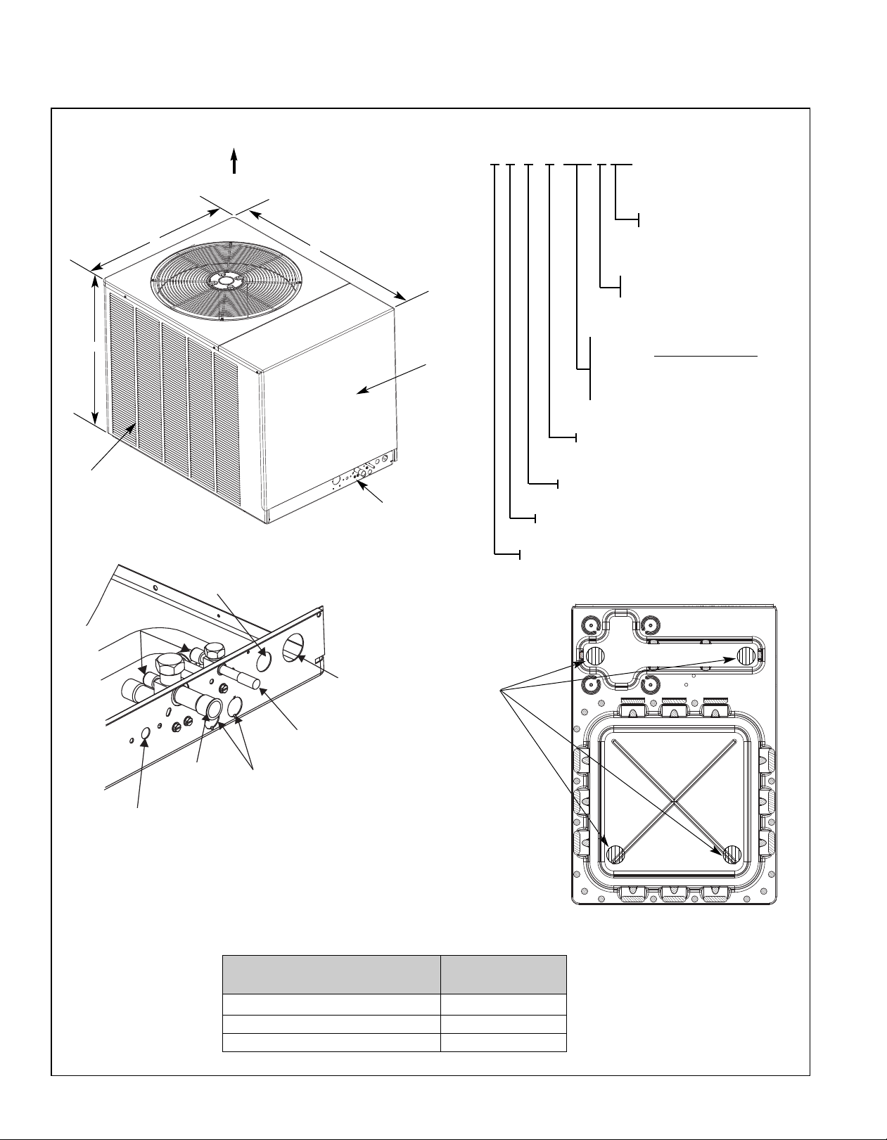
2.3 Dimensions ................................................6
2.4 lectricalandPhysicalData ...................................7
2.5 ProperInstallation...........................................7
3.0 LOCATNGUNT.................................................7
3.1 Corrosive nvironment .......................................7
3.2 HeatPumpLocation .........................................8
3.3 OperationalIssues...........................................8
3.4 For Units With Space Limitations. . . . . . . . . . . . . . . . . . . . . . . . . . . . . . . . 8
3.5 CustomerSatisfactionIssues ..................................8
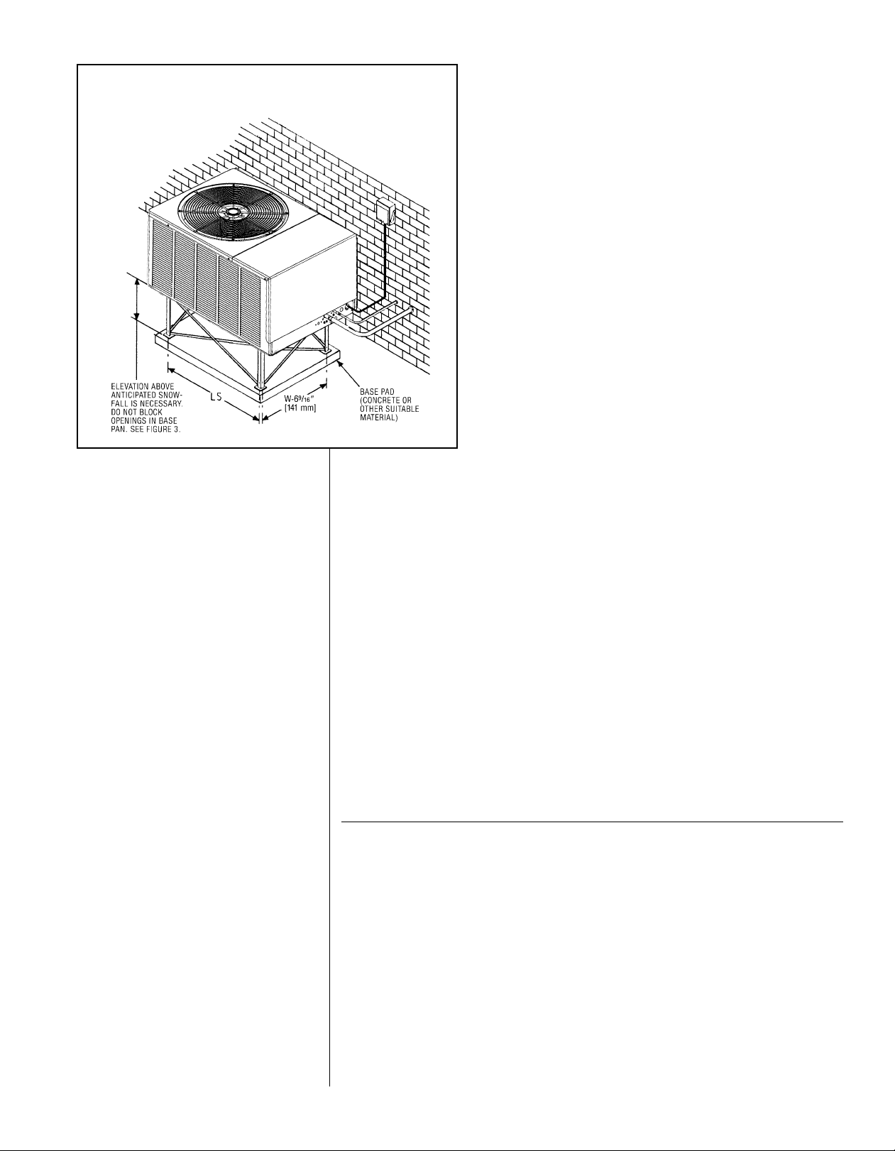
3.6 UnitMounting...............................................8
3.7 Factory-Preferred Tie-Down Method . . . . . . . . . . . . . . . . . . . . . . . . . . . . . 9
4.0 REFRGERANTCONNECTONS....................................9
4.1 Tools Required for Installing & Servicing R-410A Models . . . . . . . . . . . . . 9
4.2 SpecificationofR-410A......................................10
4.3 Quick Reference Guide for R-410A . . . . . . . . . . . . . . . . . . . . . . . . . . . . . 11
5.0 REPLACEMENTUNTS ..........................................11
6.0 NDOORCOL..................................................11
6.1 Location..................................................11
7.0 NTERCONNECTNGTUBNG.....................................12
7.1 Vapor&LiquidLines........................................12
7.2 MaximumLengthofLines....................................12
7.3 Outdoor Unit Installed Above or Below Indoor Coil . . . . . . . . . . . . . . . . . 13
7.4 TubingInstallation..........................................13
7.5 TubingConnections.........................................14
7.6 LeakTesting ..............................................15
8.0 DEMANDDEFROSTCONTROL ...................................15
8.1 DefrostInitiation............................................15
8.2 DefrostTermination.........................................16
8.3 TemperatureSensors .......................................16
8.4 DefrostTestMode..........................................16
8.5 Trouble Shooting Demand Defrost . . . . . . . . . . . . . . . . . . . . . . . . . . . . . 16
9.0 COMPRESSOR CRANKCASE HEAT (CCH) . . . . . . . . . . . . . . . . . . . . . . . . . . 16
10.0 HARDSTARTCOMPONENTS.....................................16
11.0 H GH & LOW PRESSURE CONTROLS (HPC AND LPC) . . . . . . . . . . . . . . . . 17
11.1 vacuationProcedure.......................................17
12.0 CONDENS NG UN TS EQU PPED W TH COMFORT CONTROL2
SYSTEM™.....................................................18
12.1 ControlDescription .........................................18
12.2 Comfort Contro 2ControlWiring ...............................20
12.3 Comfort Contro 2ICCControlOperation.........................20
12.4 Active Compressor Protection Mode . . . . . . . . . . . . . . . . . . . . . . . . . . . . 22
12.5 TestandFaultRecallModes..................................24
12.6 ICCDiagnosticCodes ....................................26-29
12.7 Conventional 24VAC Thermostat Control Wiring . . . . . . . . . . . . . . . . . . 29
12.8 Typical Thermostat Wiring Diagrams. . . . . . . . . . . . . . . . . . . . . . . . . . . . 30
12.9 ICC Control Operation with Conventional Thermostat Wiring . . . . . . . . . 31
12.10 Active Compressor Protection Mode . . . . . . . . . . . . . . . . . . . . . . . . . . . . 33
12.11 TestandFaultRecallModes..................................35
13.0 ELECTRCALWRNG ...........................................37
13.1 PowerWiring..............................................37
13.2 Grounding ................................................37
13.3 ControlWiring .............................................37
14.0 STARTUP&PERFORMANCE ....................................38
15.0 CHECKNGARFLOW ...........................................38
16.0 CHECK NG REFR GERANT CHARGE . . . . . . . . . . . . . . . . . . . . . . . . . . . . . . 39
16.1 Charging Units with R-410A Refrigerant . . . . . . . . . . . . . . . . . . . . . . . . . 39
16.2 ChargingByLiquidPressure..................................39
16.3 ChargingByWeight.........................................39
16.4 FinalLeakTesting..........................................40
17.0 ACCESSORES.................................................40
17.1 DualFuelKitModel.........................................40
17.2 Remote Outdoor Temperature Model . . . . . . . . . . . . . . . . . . . . . . . . . . . 40
18.0 TROUBLESHOOTNG............................................40
18.1 Serial Communicating System Initial Startup. . . . . . . . . . . . . . . . . . . . . . 40
18.2 Replacement of Comfort Contro 2System™ Control Board . . . . . . . . . . 41
18.3 lectricalChecksFlowChart..................................42
18.4 Cooling Mechanical Checks Flow Chart . . . . . . . . . . . . . . . . . . . . . . . . . 43
18.5 Defrost Mechanical Checks Flow Chart. . . . . . . . . . . . . . . . . . . . . . . . . . 44
18.6 General Troubleshooting Chart . . . . . . . . . . . . . . . . . . . . . . . . . . . . . . . . 45
18.7 ServiceAnalyzerCharts...................................46-50
18.8 SubcoolingCalculation ......................................51
19.0 WRNGDAGRAMS ..........................................52-53
2