1
A few simple tools are required:
- Measuring tape
- Power drill, drill bits
-
1⁄4”Hex head and/or Phillips driver bit
- Pencil
GETTING STARTED
1 1⁄4”
Hex Head
Bracket
Screw
Head rail
Extension
and Sidemount
Bracket
(optional)
Spacer
Block
(optional)
Additional fasteners other than those
sent with your shade may be required
depending on the mounting surface.
Wallboard and plaster require the
use of anchors such as expansion
or toggle bolts. Brick, tile or stone
need special plugs and drill bits.
Remember to always pre-drill holes
in wood to avoid splitting.
Mounting
Bracket
Hold
Down
Bracket
(optional)
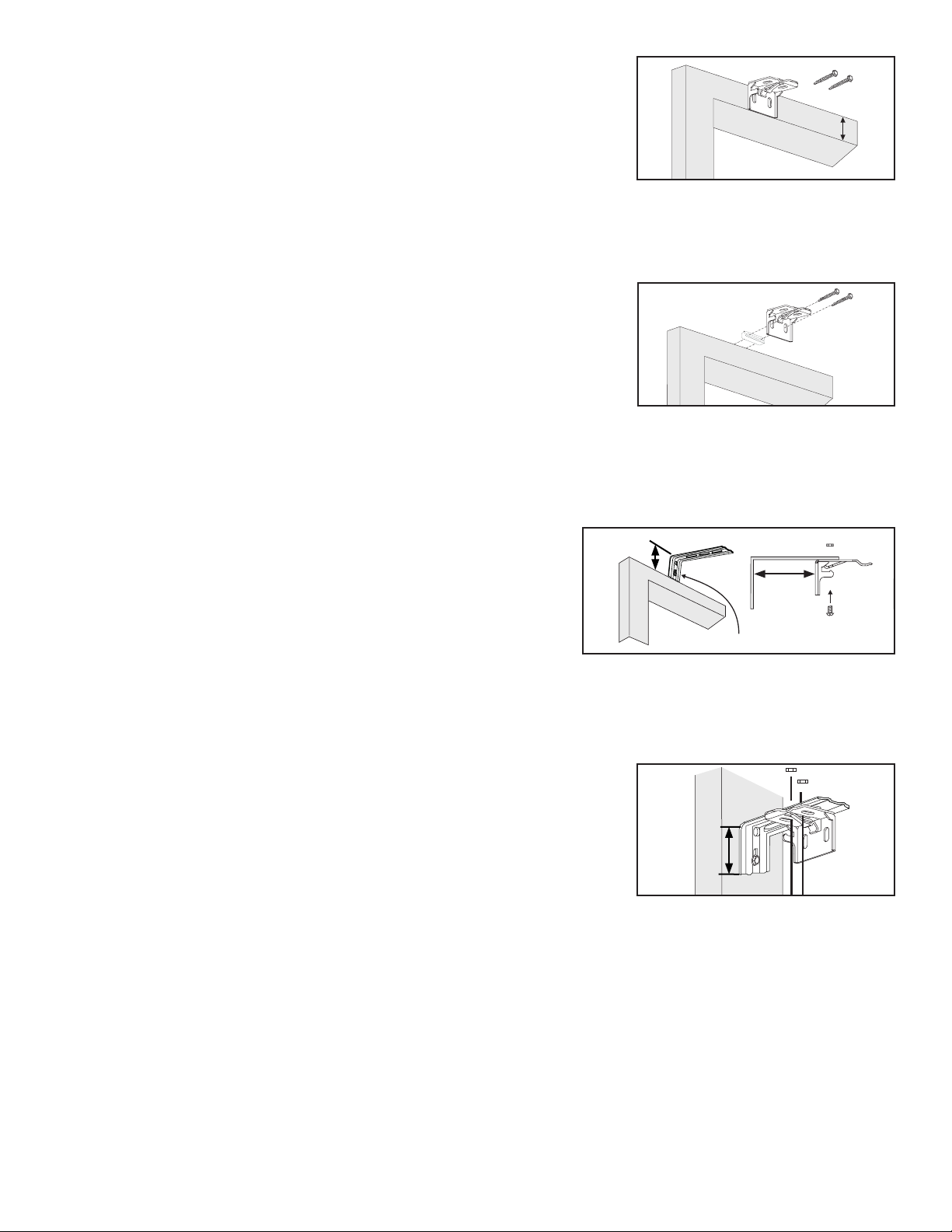
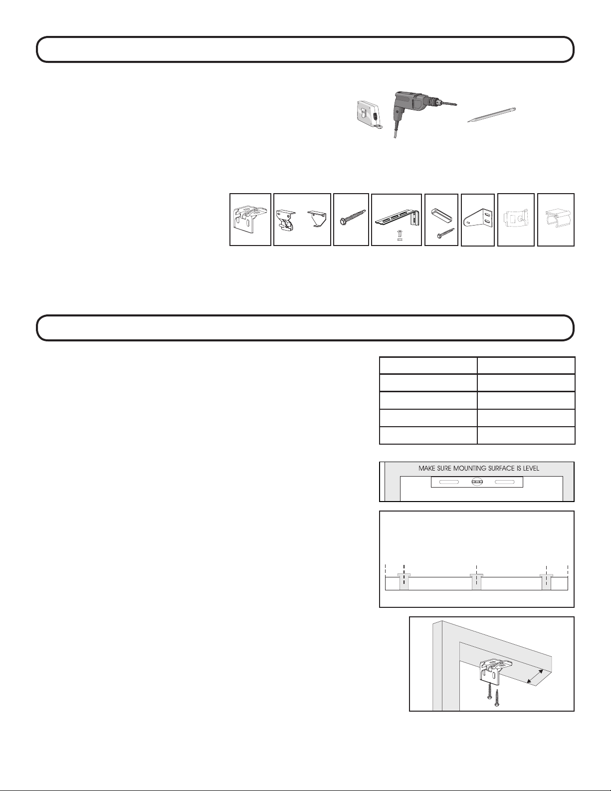
STEP 1: BRACKET INSTALLATION
PN: CS5402 PN: 20201012 PN: CS1000 PN: CS2000
Shades are shipped with the required number of brackets
for proper installation. End brackets should be located
approximately 3” from either end. Depending on the width of
the shade, additional brackets may be necessary, evenly spaced
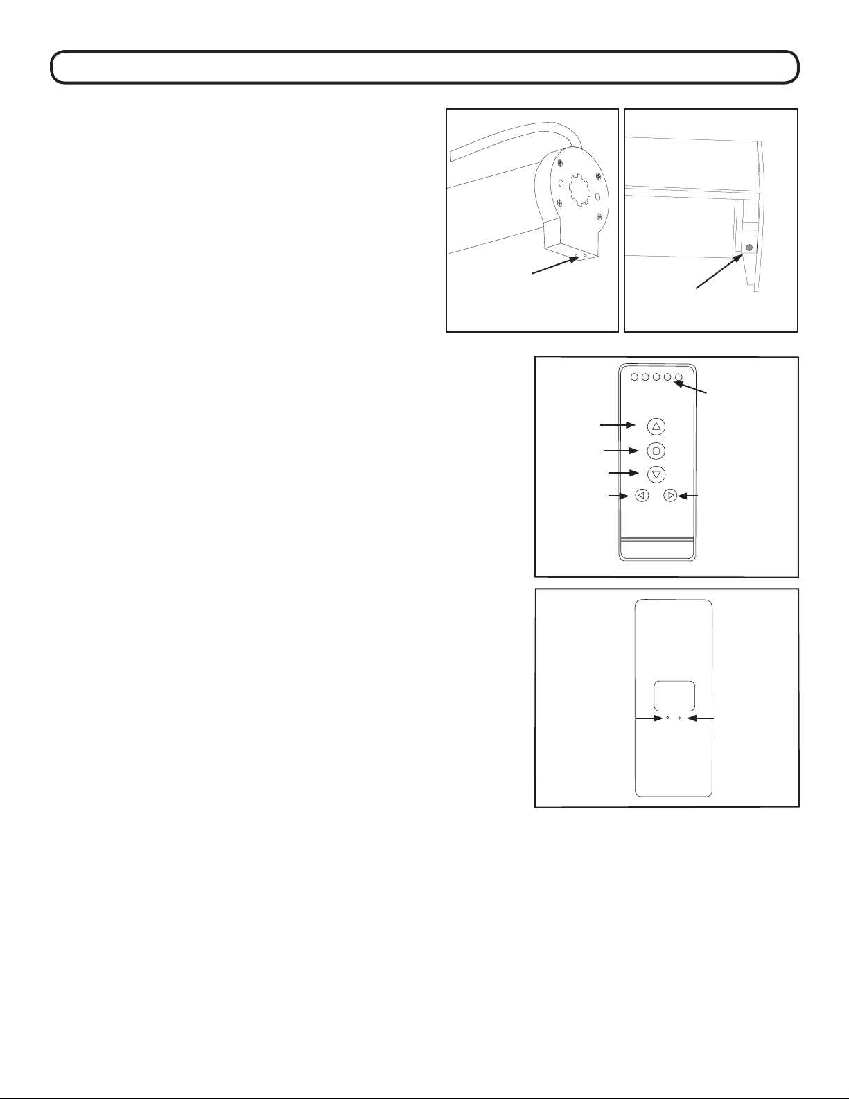
between the two end brackets. If mounting the battery wand
to the head rail, bracket positions may need to be adjusted
to accomodate the battery wand. You must have at least 19”
between bracket centerlines to t the battery wand.
Using the installation bracket as a template, measure to the
edge of the bracket and mark the hole locations with a pencil
for drilling.
Brackets must be in line and level. Shim brackets on inside
mounts if necessary. e head rail must be level for the shade
to operate properly.
Shade Width # of Brackets
Up to 40” 2
>40” - 72” 3
>72”- 84” 4
>84” and up 5
INSIDE MOUNT
e minimum mounting depth for an inside mount is 1”.
A minimum of 3 3⁄4”is needed to fully recess the shade.
Make sure the brackets are level and aligned.
Attach using two screws. Inside Mount
Shallow Mount - Minimum 1”surface
Flush Mount - Minimum 3 3⁄4”surface
1”
Wall
Mount
Battery
Wand Clip
head rail
Mount
Battery
Wand Clip
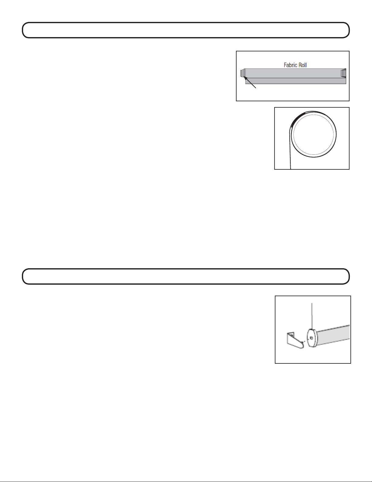
Mounting
Brackets for
Shades without
head rail
PN: CS5171 PN: CS5492
PN: CS1101
PN: CS5002(W or BLK)
CS5008 (W or BLK)
CS5529
CS5530
Depends on size of
shade
SHADES WITH HEAD RAIL
3” 3”
19” min. between
bracket center
lines to mount
battery wand to
head rail