commercial cool CCF43P40 User manual

42 in. Ceiling Fan
User Manual
MODEL CCF43P40

Page 2
ENGLISH
Thank you for purchasing our
Commercial Cool product. This
easy-to-use manual will guide you
in getting the best use of your fan.
Remember to record the model
and serial numbers. They are on a
label on the rear.
Staple your receipt to your manual.
You will need it to obtain warranty service.
Model number
Serial number
Date of purchase
PRODUCT REGISTRATION
CONTENTS
SAFETY INFORMATION
Important Safety Instructions..........................................................................................................................................3-4
SET UP & USE
Parts..............................................................................................................................................................................................5-6
Features.......................................................................................................................................................................................... 7
Preparing for Installation........................................................................................................................................................ 8
Mounting Bracket Installation........................................................................................................................................9-10
Blade Installation........................................................................................................................................................................11
Mounting Fan Assembly .................................................................................................................................................12-14
Wiring.............................................................................................................................................................................................15
Securing Fan to Ceiling..........................................................................................................................................................16
Light Fixture Installation........................................................................................................................................................17
Operation......................................................................................................................................................................................18
Cleaning + Maintenance........................................................................................................................................................19
TROUBLESHOOTING & WARRANTY
Before You Call For Service .............................................................................................................................................. 20
Customer Service ...................................................................................................................................................................20
Troubleshooting........................................................................................................................................................................21
Limited Warranty.....................................................................................................................................................................22

Page 3
ENGLISH
SAFETY INFORMATION
IMPORTANT SAFETY INSTRUCTIONS
1. READ ALL INSTRUCTIONS BEFORE USE
2. Installation work and electrical wiring must be done by qualied
person(s) in accordance with all applicable codes and standards,
including re-rated construction.
3. Use this unit only in the manner intended by the manufacturer. If you
have any questions contact the manufacturer.
4. After making the wire connections, gently push connections into
outlet box with wire nuts pointing up. The wires should be spread
apart with the grounded conductor and the equipment grounding
conductor on one side of the outlet box and ungrounded conductor
on the other side of the outlet box.
5. Before you begin installing the fan, Switch power off at Service panel
and lock service disconnecting means to prevent power from being
switched on accidentally. When the service disconnecting means
cannot be locked, securely fasten a prominent warning device, such
as a tag, to the service panel.
6. Be cautious! Read all instructions and safety information before
installing your new fan. Review the accompanying assembly
diagrams.
7. When cutting or drilling into wall or ceiling, do not damage electrical
wiring and other hidden utilities.
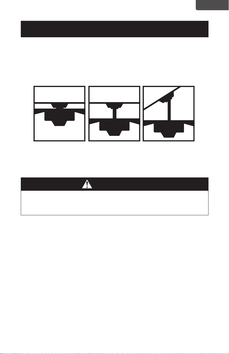
8. Make sure the installation site you choose allows the fan blades to
rotate without any obstructions. Allow a minimum clearance of 7
feet (2.1 meters) from the oor to the trailing edge of the blade.
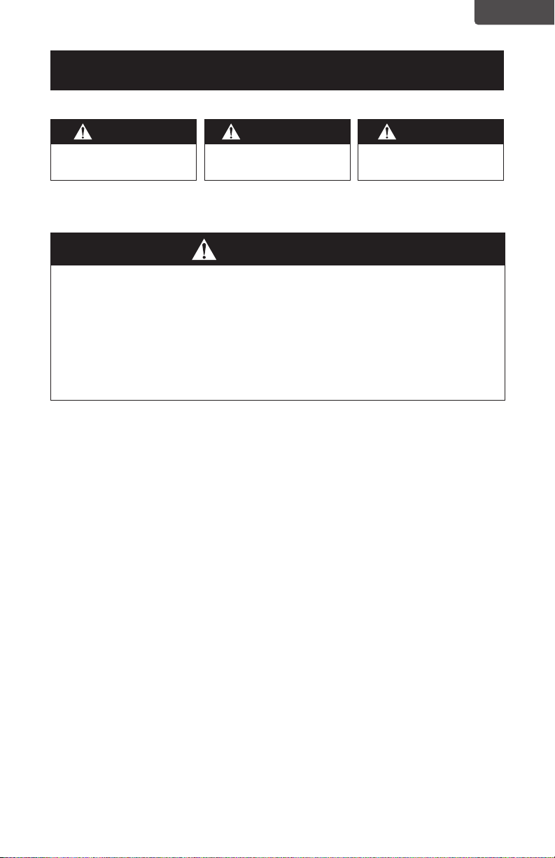
WARNING
WARNING - Hazards or unsafe
practices which COULD result in
severe personal injury or death
DANGER
DANGER - Immediate hazards
which WILL result in severe
personal injury or death
CAUTION
CAUTION - Hazards or unsafe
practices which COULD result in
minor personal injury
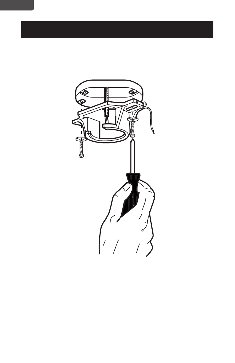
WARNING
TO REDUCE THE RISK OF FIRE, ELECTRIC SHOCK, OR PERSONAL INJURY, MOUNT
TO OUTLET BOX MARKED “ACCEPTABLE FOR FAN SUPPORT OF 35 LBS (15.9
KGS) OR LESS” AND USE MOUNTING SCREWS PROVIDED WITH THE OUTLET
BOX AND/OR SUPPORT DIRECTLY FROM BUILDING STRUCTURE. MOST OUTLET
BOXES COMMONLY USED FOR THE SUPPORT OF LUMINARIES
ARE NOT ACCEPTABLE FOR FAN SUPPORT AND MAY NEED TO BE REPLACED.
CONSULT A QUALIFIED ELECTRICIAN IF IN DOUBT.

Page 4
ENGLISH
SAFETY INFORMATION
9. To reduce the risk of re, electric shock, or personal injury, this fan
must be mounted to an outlet box marked suitable for fan support.
And use mounting screws provided with the outlet box. (Mounting
must support at least 35 lbs. (15.9 kgs)
10. WARNING: TO REDUCE THE RISK OF PERSONAL INJURY Do not
bend blade holders during installation to motor, balancing or during
cleaning. Do not insert foreign object between rotating blades.
11. Attach the mounting bracket using only the hardware supplied with
the outlet box. Fan is only to be mounted to an outlet box marked
“Acceptable for Fan Support”.
12. Do not install within a zone measured 3 feet horizontally and 8 feet
vertically from the top of the bathtub rim or shower stall threshold.
13. Before servicing or cleaning unit, Switch power off at Service panel
and lock service disconnecting means to prevent power from being
switched on accidentally. When the service disconnecting means
cannot be locked, securely fasten a prominent warning device, such
as a tag, to the service panel.
14. All set screws must be checked and re-tightened where necessary
before installation.
15. Installation work and electrical wiring must be done by qualied
person(s) in accordance with applicable codes and standards,
including re-rated construction.
READ AND SAVE THESE
INSTRUCTIONS
HOUSEHOLD USE ONLY
WARNING
To reduce the risk of re or electric shock, do not use this fan with any solid-state
speed control device.
WARNING
To reduce the risk of personal injury, do not bend the blade brackets when installing
the brackets, balancing the blades, or cleaning the fan. Do not insert forgeign objects
in between rotating fan blades. Use only with light kits marked suitable for use in
damp locations.

Page 5
ENGLISH
SET UP & USE
PARTS
Mounting Bracket
Blade (3)
*Light Fixture
Hardware Pack
* Bulbs not included with light xture (2) type A-19, 9W bulbs required.
Canopy
Screws
Screws for fan blade
Wire Connectors
Washers for fan blade
Motor Housing
Slide Switch
6” Downrod
Pull Chains (2)
Pull Chain Extentions (2)

Page 6
ENGLISH
Ladder
Screwdrivers
Pliers
Wire Strippers
Electrical Tape
(optional) Power drill and drill bit
A. Mounting Bracket
B. Canopy
C. 6” Downrod assembly
D. Yoke Cover
E. Fan Motor Assembly
F. Motor Cover
G. Glass Cover (Light Fixture)
H. Fan Blades (3)
Pull Chain (2)
Pull Chain Extensions (2)
A
B E
F
G
C
D
H
RECOMMENDED TOOLS
PARTS INCLUDED
SET UP & USE

Page 7
ENGLISH
SET UP & USE
FEATURES
Downrod
Installation
For normal ceilings
Vaulted Ceiling
Installation
May require a
longer downrod
(sold separately)
CAUTION
To reduce the risk of injury to persons, the fan must be installed so that the blades are
at a height greater than 7 feet (2.1 meters) above the floor.
This fan is designed for indoor use only.
Flush
Installation
For normal ceilings

Page 8
ENGLISH
PREPARING FOR INSTALLATION
1. Unpack and inspect fan carefully to be certain all contents are included.
WARNING: Turn off power at the breaker box or fuse panel to avoid possible
electrical shock.
2. Use a listed metal outlet box suitable for fan support (rated for 35 lbs (15.9 kgs).
Before attaching fan to outlet box, ensure the outlet box is securely fastened by at
least two points to a structural ceiling member (a loose box will cause the fan to
wobble).
SET UP & USE

Page 9
ENGLISH
MOUNTING BRACKET INSTALLATION
3. Remove the screws from the two mating holes (2) on the canopy. Loosen (do not
remove) the screws in the mating slots (1) on the canopy. Rotate the mounting
bracket and remove from the canopy.
2
1
1
2
2
1
1
2
SET UP & USE

Page 10
ENGLISH
4. Install mounting bracket to outlet box in ceiling using the screws and washers
provided with the outlet box.
SET UP & USE

Page 11
ENGLISH
5. Choose a MOUNTING OPTION (Shown on page 13):
FLUSH INSTALLATION OPTION
If installing ush, remove the screws from the canopy and reinstall 3 screws to attach
the canopy to the motor housing as shown.
Complete the wiring as shown on page 14. It will require two people to complete this
installation. Someone will need to hold the canopy and motor housing, while the wires
are being connected.
Proceed to secure the fan to the ceiling as shown on page 15, step 10.
NORMAL DOWNROD OPTION
6. Remove clamp pin (1) and cross pin (2) from
downrod (3). Proceed to DOWNROD
INSTALLATION on the next page.
1
2
3
Screws Motor
Housing
Canopy
SET UP & USE

Page 12
ENGLISH
SET UP & USE
DOWNROD INSTALLATION
7. Insert motor wires through the selected downrod and insert the downrod into
the downrod coupling. Make sure to align the hole in the downrod with the hole
in the downrod coupling. Install cross pin (1) removed in step 6 through coupling
and downrod. Insert clamp pin (2) into cross pin until it snaps into place. Tighten
set screws (3) in coupling. Slide coupling cover (4) and canopy onto the downrod
above the coupling cover. PROCEED TO PAGE 13, STEP 8.
1
4
3
2
Downrod Coupling
1
4
3
2
Downrod Coupling

Page 13
ENGLISH
MOUNTING
8. Carefully lift fan assembly onto mounting bracket. Rotate fan until notch on
downrod ball (1) engages the ridge on the mounting bracket (2). This will allow for
hands free wiring for downrod fan installation.
NOTE: If you are installing the fan ush, you will need assistance holding the fan while
doing the wiring.
SET UP & USE

Page 14
ENGLISH
SET UP & USE
WIRING
9. The frequency switches on your receiver and transmitter have been preset at the
factory. Please recheck to make sure the switches on transmitter and receiver are
set to the same position, any combination of settings will operate the fan as long as
the transmitter and receiver are set to the same position.
Use supplied wire connectors to connect the wires.
BLK BLK
BLUE
Fan
Light
GREEN
WHITE
REMOTE
RECEIVER
Live
Neutral
Ground
FANCEILING

Page 15
ENGLISH
SECURE TO CEILING
10. The canopy has two mating slots (1) and two mating holes (2). Position both slots
on canopy directly under and in line with two screws in the mounting bracket (3).
Lift the canopy, allowing the two screws to slide into the mating slots. Rotate the
canopy until both screws from the mounting bracket drop into the slot recesses.
Tighten screws securely. Install two screws into the mating holes of the canopy
and tighten to secure the canopy to the mounting bracket.
NOTE: For downrod fans, slide the canopy up to the mounting bracket.
2
3
1
2
3
1
SET UP & USE

Page 16
ENGLISH
SET UP & USE
BLADE INSTALLATION
11. Attach the blades to the blade brackets in the fan motor assembly using 3 screws
and 3 washers for each blade.
Remove 3 light kit screws and 3 washers from the fan motor housing. Insert the 2
appropriate sized light kit connections from the fan motor assembly to the motor
cover. Secure the motor cover to the fan motor assembly with the previously
removed screws and washers. Turn washer to lock in place and tighten screws
Blade Bracket
Screw
Washers
Blade
Blade Bracket
Light Kit Screw
Star Washer
Light Kit Connections

Page 17
ENGLISH
LIGHT FIXTURE INSTALLATION
12. Install 2 light bulbs Type A-19, 9W max (not included).
13. Locate the indentations on the neck of the glass (2) and align with the protrusions
from the light kit (1). Lift the glass up allowing the protrusions to engage the
indentations on the glass, and twist the glass clockwise to lock into place.
1
2
1
2
Blade Bracket
Screw
Washers
Blade
Blade Bracket
SET UP & USE

Page 18
ENGLISH
Page 18
SET UP & USE
OPERATION
The slide switch controls direction, forward or reverse.
Warm weather - switch on left position.
Fan turns counterclockwise direction. A downward air ow creates a cooling effect as
shown in illustration A.
Cool weather - switch on right position (see image).
Fan turns clockwise direction. An upward airow moves warm air off the ceiling area
as shown in illustration B (This function will usually be used in the winter).
NOTE: Turn off and wait for fan to stop before changing the setting
of the forward/reverse slide switch.

Page 19
ENGLISH
CLEANING + MAINTENANCE
1. Because of the fan’s natural movement, some connections may become loose.
Check the support connections, brackets, and blade attachments twice a year.
Make sure they are secure.
2. Clean your fan periodically to help maintain its new appearance over the years.
Do not use water when cleaning. This could damage the motor, or the wood, or
possibly cause electrical shock.
3. Use only a soft brush or lint-free cloth to avoid scratching the nish. The plating is
sealed with a lacquer coating to minimize discoloration or tarnishing.
4. There is no need to oil your fan. The motor has permanently lubricated bearings.
5. To change light bulbs, see page 17.
CLEANING + MAINTENANCE

Page 20
ENGLISH
SET UP & USE
BEFORE YOU CALL FOR SERVICE
IF THE APPLIANCE FAILS TO OPERATE:
Check for a blown circuit fuse or a tripped main circuit breaker. If these seem to be
operating properly, test the outlet with another appliance.
IF NONE OF THE ABOVE SOLVES THE PROBLEM, CONTACT A QUALIFIED
TECHNICIAN. DO NOT TRY TO ADJUST OR REPAIR THE APPLIANCE YOURSELF.
IMPORTANT
DO NOT RETURN THIS PRODUCT TO THE STORE
If you have a problem with this product, please contact the
W Appliance Co. Customer Satisfaction Center at
DATED PROOF OF PURCHASE, MODEL # AND SERIAL #
REQUIRED FOR WARRANTY SERVICE
Table of contents
Languages:
Other commercial cool Fan manuals

commercial cool
commercial cool CFF16B User manual

commercial cool
commercial cool CCF45P10 User manual

commercial cool
commercial cool CCFWR16W User manual

commercial cool
commercial cool CCF54P50 User manual

commercial cool
commercial cool CCF45P20 User manual

commercial cool
commercial cool CCF55P60 User manual
Popular Fan manuals by other brands

Ferono
Ferono FKP SILENT Installation directions

AirTech
AirTech Air+ WALL Installation & commissioning instructions

Bestron
Bestron ADV45S instruction manual

HOMCOM
HOMCOM 824-062V90 manual

Henley Fan
Henley Fan 6HE84+LK owner's manual

Zehnder Rittling
Zehnder Rittling Eversky 500 Installation, service and user manual