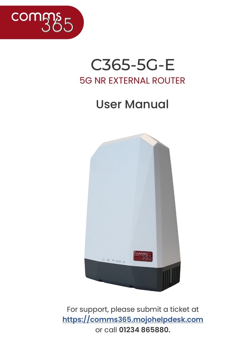
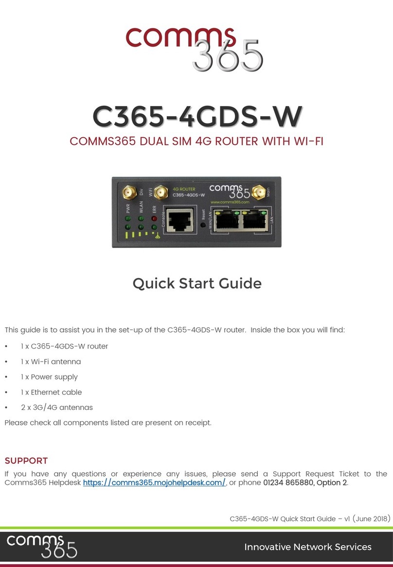
Comms365 C365-5G-Mini User manual

C365-5G-Mini User Manual CB-V1 .1
www.comms365.com | 01234 865880 | sales@comms365.com
C365-5G-Mini
COMMS365 5G Router
USER MANUAL

2
C365-5G-Mini User Manual CB-V1.1
www.comms365.com | 01234 865880 | sales@comms365.com
Contents
2 Hardware Installation . . . . . . . . . . . . . . . . . . . . . . . . . . . . . . . . . . . . . . . . . . . . . . . . . . . . . . . . .5
2.1 Overall Dimension . . . . . . . . . . . . . . . . . . . . . . . . . . . . . . . . . . . . . . . . . . . . . . . . . . . .5
2.2 The Ports . . . . . . . . . . . . . . . . . . . . . . . . . . . . . . . . . . . . . . . . . . . . . . . . . . . . . . . . . . . . . .5
2.3 Installation . . . . . . . . . . . . . . . . . . . . . . . . . . . . . . . . . . . . . . . . . . . . . . . . . . . . . . . . . . . .6
2.4 SIM/UIM card installation . . . . . . . . . . . . . . . . . . . . . . . . . . . . . . . . . . . . . . . . . . . .6
2.5 The installation of the terminal block . . . . . . . . . . . . . . . . . . . . . . . . . . . . . .7
2.6 Grounding . . . . . . . . . . . . . . . . . . . . . . . . . . . . . . . . . . . . . . . . . . . . . . . . . . . . . . . . . . . .8
2.7 Power Supply. . . . . . . . . . . . . . . . . . . . . . . . . . . . . . . . . . . . . . . . . . . . . . . . . . . . . . . . . 8
2.8 LED and Check Network Status. . . . . . . . . . . . . . . . . . . . . . . . . . . . . . . . . . . . . 8
3 Software Configuration. . . . . . . . . . . . . . . . . . . . . . . . . . . . . . . . . . . . . . . . . . . . . . . . . . . . . . . . . 9
3.1 Overview. . . . . . . . . . . . . . . . . . . . . . . . . . . . . . . . . . . . . . . . . . . . . . . . . . . . . . . . . . . . . . . 9
3.2 How to log into the Router. . . . . . . . . . . . . . . . . . . . . . . . . . . . . . . . . . . . . . . . . . 9, 10, 11
3.3 Router status. . . . . . . . . . . . . . . . . . . . . . . . . . . . . . . . . . . . . . . . . . . . . . . . . . . . . . . . . 12
3.3.1 Status overview. . . . . . . . . . . . . . . . . . . . . . . . . . . . . . . . . . . . . . . . . . . .12
3.3.2 Network status. . . . . . . . . . . . . . . . . . . . . . . . . . . . . . . . . . . . . . . . . . . . 13
3.3.3 Firewall status. . . . . . . . . . . . . . . . . . . . . . . . . . . . . . . . . . . . . . . . . . . . .14
3.3.4 Routes. . . . . . . . . . . . . . . . . . . . . . . . . . . . . . . . . . . . . . . . . . . . . . . . . . . . . 14
3.3.5 System log. . . . . . . . . . . . . . . . . . . . . . . . . . . . . . . . . . . . . . . . . . . . . . . . 14
3.3.6 Kernel log. . . . . . . . . . . . . . . . . . . . . . . . . . . . . . . . . . . . . . . . . . . . . . . . . .15
3.3.7 Realtime graphs. . . . . . . . . . . . . . . . . . . . . . . . . . . . . . . . . . . . . . . . . . 15
3.4 System Configuration. . . . . . . . . . . . . . . . . . . . . . . . . . . . . . . . . . . . . . . . . . . . . . . 16
3.4.1 Setup wizard. . . . . . . . . . . . . . . . . . . . . . . . . . . . . . . . . . . . . . . . . . . . . . . 16
3.4.2 System. . . . . . . . . . . . . . . . . . . . . . . . . . . . . . . . . . . . . . . . . . . . . . . . . . . . . 16, 17
3.4.3 Password. . . . . . . . . . . . . . . . . . . . . . . . . . . . . . . . . . . . . . . . . . . . . . . . . .18
3.4.4 NTP. . . . . . . . . . . . . . . . . . . . . . . . . . . . . . . . . . . . . . . . . . . . . . . . . . . . . . . . .18
3.4.5 Backup/Restore. . . . . . . . . . . . . . . . . . . . . . . . . . . . . . . . . . . . . . . . . . 19
3.4.6 Upgrade. . . . . . . . . . . . . . . . . . . . . . . . . . . . . . . . . . . . . . . . . . . . . . . . . . 19
3.4.7 Reset. . . . . . . . . . . . . . . . . . . . . . . . . . . . . . . . . . . . . . . . . . . . . . . . . . . . . . .20
3.4.8 Reboot. . . . . . . . . . . . . . . . . . . . . . . . . . . . . . . . . . . . . . . . . . . . . . . . . . . . .20
3.5 Services configuration. . . . . . . . . . . . . . . . . . . . . . . . . . . . . . . . . . . . . . . . . . . . . . 21
3.5.1 ICMP check. . . . . . . . . . . . . . . . . . . . . . . . . . . . . . . . . . . . . . . . . . . . . . . . .21
3.5.2 VRRP. . . . . . . . . . . . . . . . . . . . . . . . . . . . . . . . . . . . . . . . . . . . . . . . . . . . . . . .22

3
C365-5G-Mini User Manual CB-V1.1
www.comms365.com | 01234 865880 | sales@comms365.com
3.5.3 Failover (link backup) . . . . . . . . . . . . . . . . . . . . . . . . . . . . . . . . . . . .22
3.5.4 DTU. . . . . . . . . . . . . . . . . . . . . . . . . . . . . . . . . . . . . . . . . . . . . . . . . . . . . . . . . 23
3.5.5 SNMP. . . . . . . . . . . . . . . . . . . . . . . . . . . . . . . . . . . . . . . . . . . . . . . . . . . . . . . 24, 25
3.5.6 GPS. . . . . . . . . . . . . . . . . . . . . . . . . . . . . . . . . . . . . . . . . . . . . . . . . . . . . . . . . 26
3.5.7 SMS. . . . . . . . . . . . . . . . . . . . . . . . . . . . . . . . . . . . . . . . . . . . . . . . . . . . . . . . . 27, 28
3.5.8 VPN. . . . . . . . . . . . . . . . . . . . . . . . . . . . . . . . . . . . . . . . . . . . . . . . . . . . . . . . . 29
3.5.8.1 IPSEC. . . . . . . . . . . . . . . . . . . . . . . . . . . . . . . . . . . . . . . . . . . . .29
3.5.8.2 PPTP. . . . . . . . . . . . . . . . . . . . . . . . . . . . . . . . . . . . . . . . . . . . . 30, 31
3.5.8.3 L2TP. . . . . . . . . . . . . . . . . . . . . . . . . . . . . . . . . . . . . . . . . . . . . .32
3.5.8.4 OpenVPN. . . . . . . . . . . . . . . . . . . . . . . . . . . . . . . . . . . . . . . .33
3.5.8.5 GRE tunnel. . . . . . . . . . . . . . . . . . . . . . . . . . . . . . . . . . . . . . 34
3.5.9 DDNS. . . . . . . . . . . . . . . . . . . . . . . . . . . . . . . . . . . . . . . . . . . . . . . . . . . . . . . .35, 36,
3.5.10 Connect Radio Module. . . . . . . . . . . . . . . . . . . . . . . . . . . . . . . . . . .37
3.6 Network Configuration. . . . . . . . . . . . . . . . . . . . . . . . . . . . . . . . . . . . . . . . . . . . . . . .38
3.6.1 Operation Mode. . . . . . . . . . . . . . . . . . . . . . . . . . . . . . . . . . . . . . . . . . . . 38
3.6.1.1 Gets two LAN Ethernet Port for H685. . . . . . . . . . . 38
3.6.2 Mobile configuration. . . . . . . . . . . . . . . . . . . . . . . . . . . . . . . . . . . . . . 39
3.6.3 Cell mobile data limitation. . . . . . . . . . . . . . . . . . . . . . . . . . . . . . . .40
3.6.4 LAN settings. . . . . . . . . . . . . . . . . . . . . . . . . . . . . . . . . . . . . . . . . . . . . . . . .41, 42
3.6.5 Wired-WAN . . . . . . . . . . . . . . . . . . . . . . . . . . . . . . . . . . . . . . . . . . . . . . . . .43
3.6.6 Wi-Fi Settings. . . . . . . . . . . . . . . . . . . . . . . . . . . . . . . . . . . . . . . . . . . . . . .44
3.6.6.1 Wi-Fi General configuration. . . . . . . . . . . . . . . . . . . .44
3.6.6.2 Wi-Fi Advanced configuration. . . . . . . . . . . . . . . . 45
3.6.6.3 Wi-Fi Interface configuration. . . . . . . . . . . . . . . . . 45, 46
3.6.6.4 Wi-Fi AP Client. . . . . . . . . . . . . . . . . . . . . . . . . . . . . . . . . . .47
3.6.7 Interfaces Overview. . . . . . . . . . . . . . . . . . . . . . . . . . . . . . . . . . . . . . . .48
3.6.8 Firewall. . . . . . . . . . . . . . . . . . . . . . . . . . . . . . . . . . . . . . . . . . . . . . . . . . . . . . 49
3.6.8.1 General Settings. . . . . . . . . . . . . . . . . . . . . . . . . . . . . . . . .49
3.6.8.2 Port Forwards. . . . . . . . . . . . . . . . . . . . . . . . . . . . . . . . . . . 49
3.6.8.3 traffic rules. . . . . . . . . . . . . . . . . . . . . . . . . . . . . . . . . . . . . . 50, 51
3.6.8.4 DMZ. . . . . . . . . . . . . . . . . . . . . . . . . . . . . . . . . . . . . . . . . . . . . . .52
3.6.8.5 Security. . . . . . . . . . . . . . . . . . . . . . . . . . . . . . . . . . . . . . . . . . 52
3.6.9 Static Routes. . . . . . . . . . . . . . . . . . . . . . . . . . . . . . . . . . . . . . . . . . . . . . . .53
3.6.10 Switch. . . . . . . . . . . . . . . . . . . . . . . . . . . . . . . . . . . . . . . . . . . . . . . . . . . . . . .53

4
C365-5G-Mini User Manual CB-V1.1
www.comms365.com | 01234 865880 | sales@comms365.com
3.6.11 DHCP and DNS. . . . . . . . . . . . . . . . . . . . . . . . . . . . . . . . . . . . . . . . . . . . . . 54
3.6.12 Diagnostics. . . . . . . . . . . . . . . . . . . . . . . . . . . . . . . . . . . . . . . . . . . . . . . . .55
3.6.13 Loopback Interface. . . . . . . . . . . . . . . . . . . . . . . . . . . . . . . . . . . . . . . .55
3.6.14 Dynamic Routing. . . . . . . . . . . . . . . . . . . . . . . . . . . . . . . . . . . . . . . . . . 56
3.6.15 QoS. . . . . . . . . . . . . . . . . . . . . . . . . . . . . . . . . . . . . . . . . . . . . . . . . . . . . . . . . .57

5
C365-5G-Mini User Manual CB-V1.1
www.comms365.com | 01234 865880 | sales@comms365.com
2. Hardware Installation
This chapter mainly describes the appearance, model and function of the C365-5G-MINI series and
how to install and set the configurations.
1. Dimensions
2. Accessories
3. Installation
2.1 Overall Dimension
2.2 The Ports

6
C365-5G-Mini User Manual CB-V1.1
www.comms365.com | 01234 865880 | sales@comms365.com
•LAN: LAN RJ45 Ethernet ports.
•WAN: WAN RJ45 Ethernet ports.
•RST: Sys reset button
•PWR: DC power socket. DC5~40V, DC5~50V option depends on the router version
•VCC: DC wire positive pole. DC5~40V, DC5~50V option depends on the router version
•GND: DC wire ground
•GND: Serial ground
•RX: Serial receiving
•TX: Serial transmission
•RST: Reset router
•DIO0: Digit I/O port 0
•IDO1: Digit I/O port 1
•NC: No connection
•GND: DC wire ground
•VCC: DC wire positive pole. DC5~40V, DC5~50V option depends on the router version
•WPS: WPS button
Antenna Connection Table
Antenna Connector
Marks
Cell
for main cell antenna
Aux
for auxiliary cell antenna
Wi-Fi / WLAN
for Wi-Fi antenna
GPS
for GPS antenna
2.3 Installation
The C365-5G-MINI should be installed and configured properly before using. The installation and
configuration should be done under supervision or by a qualified engineer.
Attention:
Do not install or connect/disconnect the cable when its power is turned on.
2.4 SIM/UIM card installation
If your router has a SIM/UIM card protector, please remove it, insert the sim card correctly, and close.
If your router has no SIM/UIM card protector, please insert the sim card correctly.
Attention: If the SIM/UIM card is not fully inserted, the router cannot identify the card normally.
Please check that the card is fully inserted.

7
C365-5G-Mini User Manual CB-V1.1
www.comms365.com | 01234 865880 | sales@comms365.com
2.5 The installation of the terminal block
Only applicable if the router requires a terminal block. The C365-5G-MINI is provided with a DB9
connector as standard. Please use the DB9 cable to connect the C365-5G-MINI and the equipment
directly.
The following is for use with a terminal block:
The C365-5G-MINI uses a pluggable terminal to connect the user’s data and the power supply.
Spacing: 3.81mm, 10 Pin; User data and power supply suggestion: 14~24AWG. Please refer to the table
below for the interface definition of the power cable and connection sequence. The the power cable
specification and the connection sequence can be read on the labels of the C365-4G-H685. Using a
14~24AWG cable and referring to the C365-5G-MINI product label or the below interface specification,
you will need to use a screwdriver to fix the cable to the connecting jacks of the terminal. After
achieving a successful connection, you need to insert the terminal into the corresponding position in
the bottom of the C365-5G-MINI router.
Notes: The connection sequence should be
accurate. Cable’s insulating striping length is
about 7mm. (For safety, the length of the wire
should be at least 7mm long.)
Attention:
1. The power cable should be connected correctly. We “suggest double checking it before
switching it on. An incorrect connection may destroy the equipment.
2. Power terminals: Pin 1 and Pin 2;
3. Pin 2 is “GND”, PIN 1 is power input “Vin” (DC5~40V, or DV5~50V).
PIN
Signal
Description
Note
1
VCC
+5-40V DC Input, +5~50V option
Current: 12V/1A
2
GND
Ground
3
TX
Transmit Data
4
RX
Receive Data
5
PGND
Ground
6
RST
Reset
7
DIO0
General Purpose I/O
8
DIO1
General Purpose I/O
9
NC
Not connect
I/O Terminal on router
Serial port (RS485 or RS232)
Port 3 (GND)
Pin 5
Port 4 (RX)
Pin 2
Port 5 (TX)
Pin 3
Notes: If the connection is unsuccessful, then you can switch to Port4 and Port5.

8
C365-5G-Mini User Manual CB-V1.1
www.comms365.com | 01234 865880 | sales@comms365.com
2.6 Grounding
To ensure the safe, stable and reliable operation of the C365-4G-H685, the router casing should be
grounded properly.
2.7 Power Supply
The C365-5G-MINI can be used in difficult environments and usually the power range is very large.
So, in order to overcome troublesome environments and improve the stability of the system, the
C365-5G-MINI is designed with advanced power management technology. The DC power supply to
the device is transferred using the terminal, PIN 2(GND) and PIN 1(Vin). Please refer to the above table
for specifications of the terminal.
Normally, the C365-5G-MINI router inputs a power supply of +5~+40V (if your H685 support 50V, the
option is +5~+50V). In most cases, the standard configuration is 12V/1A.
2.8 LED and Check Network Status
Please connect the antenna after you successfully connect the cable. Insert the valid SIM/UIM card
and provide the power to the router via the cable. When the power is turned on the SYS LED starts to
blink after a few seconds, this means that the system start-up has been started; if the CELL LED lights
up, this means that the network is online; if the VPN light works, this means that the VPN tunnel has
been set up. Please refer to the below table as a guide for the indication lights.

9
C365-5G-Mini User Manual CB-V1.1
www.comms365.com | 01234 865880 | sales@comms365.com
SYS
On for 25 seconds
On for 25 seconds after power supply
Blink
System set-up normally
Off or still on after 25
seconds
System set-up failure
LAN
Blink
Data transmission in Ethernet
Off
Ethernet connection abnormal
On
Ethernet is connected
VPN
On
VPN tunnel set-up
Off
VPN tunnel set-up failure or unactuated
CELL
On
Access to the Internet
WIFI
On
Enable
Off
Disable
WAN
Blink
Data transmission in Ethernet
Off
Ethernet connection abnormal
On
Ethernet is connected
SIGNAL
Off
No signal, or signal checking is not ready
4s blink 1 time
Signal bar is 1
3s blink 1 time
Signal bar is 2
2s blink 1 time
Signal bar is 3
1s blink 1 time
Signal bar is 4
1s blink 2 times
Signal bar is 5
3. Software Configuration
1. Overview
2. How to log into the Router
3. How to config the web
3.1 Overview
The C365-5G-MINI router has a built-in WEB interface configuration, management and debugging
tools. The parameters require configuring first; these parameters offer flexibility for software
upgrades and testing. Users can set up and manage the parameters of the router on its interface,
detailed steps are below:
3.2 How to log into the Router
Network Configuration of the Computer
The router default parameters are as follows: _Default IP: 192.168.1.1, sub mask: 255.255.255.0.
There are two ways to set the PC’s IP address.

10
C365-5G-Mini User Manual CB-V1.1
www.comms365.com | 01234 865880 | sales@comms365.com
Option 1) Manual setting
Set the PC IP as 192.168.1.xxx (xxx = 2~254), subnet mask: 255.255.255.0, default gateway: 192.168.1.1,
primary DNS: 192.168.1.1.
Option 2) DHCP
Choose “Obtain an IP address automatically” and “Obtain DNS server address automatically”.

11
C365-5G-Mini User Manual CB-V1.1
www.comms365.com | 01234 865880 | sales@comms365.com
After obtaining the IP setting, check it by carrying out a ping test. Click the Windows start menu, run,
execute “CMD” command.
Enter “ping 192.168.1.1” in the DOS window.
This information means that the connection is active.
This information means that the connection has failed. Please check that the network cable and the
IP address setting. Please refer to Chapter 4.9.
Log into the Router
•Open the Web Browser, and type http://192.168.1.1 into the address field and press Enter.
•Type Username “admin” and Password “admin” in the Login page, and then press the “Login”
button.

12
C365-5G-Mini User Manual CB-V1.1
www.comms365.com | 01234 865880 | sales@comms365.com
•If you type in the correct Username and Password, you will get access into the Router’s status
overview page.
The password can be changed using the setup wizard. See page 19.
3.3 Router status
3.3.1 Status overview
Click “Status” in the navigation bar, and then click “Overview”.

13
C365-5G-Mini User Manual CB-V1.1
www.comms365.com | 01234 865880 | sales@comms365.com
3.3.2 Network status
The network status page shows detailed information of the cell mobile interface, WAN and LAN.
Cell mobile interface page:
WAN status page:
LAN status page:

14
C365-5G-Mini User Manual CB-V1.1
www.comms365.com | 01234 865880 | sales@comms365.com
3.3.3 Firewall status
The firewall status page shows the IPv4 and IPv6 rules and counters. The user can reset counters and
restart firewall functionality here.
3.3.4 Routes
The routes page shows rules which are currently active on this router. The ARP table is displayed as
well.
3.3.5 System log
This page shows the system log from initial system boot up. The system log is not saved when the
router restarts. It can be exported by clicking the “Export syslog” button.

15
C365-5G-Mini User Manual CB-V1.1
www.comms365.com | 01234 865880 | sales@comms365.com
3.3.6 Kernel log
This page shows the Kernel log from the system boot up. This log is not saved when the router
restarts. It can be exported by clicking the “Export syslog” button.
3.3.7 Realtime graphs
The real time graphs page shows real time system load, interfaces, traffic, etc.

16
C365-5G-Mini User Manual CB-V1.1
www.comms365.com | 01234 865880 | sales@comms365.com
3.4 System Configuration
3.4.1 Setup wizard
When you login into the router for the first time, the setup wizard appears.
Note: pressing the “Save & Next” button will save the configuration and jump to the next page. All
configurations will be applied after clicking the “Finish” button at the final step (Step Wi-Fi).
3.4.2 System
General Settings
•Local Time
Displays system time, and the user can Sync this time with the browser by clicking the “Sync with
browser” button.
•Hostname
This is the router’s name; the default name is Cell Router.
•Time zone
Select a suitable time zone. The default value is UTC.

17
C365-5G-Mini User Manual CB-V1.1
www.comms365.com | 01234 865880 | sales@comms365.com
Logging settings
•System log buffer size
The unit is KB, default value is 64 KB. If the log size is bigger than the value that has been configured,
the oldest log will be over written.
•External system log server
This is the IP address of the external log server. The user can setup a Linux machine with syslog
running as a log server.
•External system log server port
The UDP port of the external log server.
•Log output level
Log level, the default setting is debug which is the highest level, Emergency is the lowest level.
•Cron log level
This is the log level for process Cron.
•Language
The default language is set to “Auto”. The user can choose English or Chinese.

18
C365-5G-Mini User Manual CB-V1.1
www.comms365.com | 01234 865880 | sales@comms365.com
3.4.3 Password
Change the administrator’s password to create new login details. Click the “eye button” which will
show the new password that you entered.
3.4.4 NTP
NTP is the network timing protocol.
•Enable NTP client
The default value is set to enabled. The router acts as an NTP client.
•Provide NTP server
The default setting is marked as unchecked. The router acts as an NTP server.
•NTP server candidates
This is the NTP server list, multiple NTP servers are accepted. The user can click the button to
delete an entry or click the button to add a new entry.

19
C365-5G-Mini User Manual CB-V1.1
www.comms365.com | 01234 865880 | sales@comms365.com
3.4.5 Backup/Restore
This is used for configuring file backup and restoration.
For configuring backup files, click the “Download” button, an archive file will be generated and
downloaded to your PC automatically.
For restoration configuration files, you can click the “Choose File” button, then select an archived
configuration file, and click the “Upload” button, then the system will load this file and apply it, and the
router will restart.
3.4.6 Upgrade
Upload a compatible firmware to replace the running system firmware. The default setting for “Keep
settings” is checked. This means that the current configuration will be kept after the system upgrade.
An unchecked box will restore the router back to settings. We highly recommend that you check this
box “Keep settings”, otherwise there may be uncertain conflicting parameters after updating.
Click the “Choose File” button to select a compatible firmware then click the “Upload image”button.
The router will do a basic check of the uploaded file. If it is not a compatible file, an error will be
generated. For example:
If the firmware file is OK, a verification page will appear, then click the “Proceed” button, and the
system will restart.

20
C365-5G-Mini User Manual CB-V1.1
www.comms365.com | 01234 865880 | sales@comms365.com
3.4.7 Reset
Reset all the configurations back to factory settings. After clicking the “Reset” button, a window will
appear, click the “cancel” button to cancel. click the “OK” button to continue.
3.4.8 Reboot
Click the “Reboot” button and the system will restart in several seconds.
Table of contents
Other Comms365 Network Router manuals
Popular Network Router manuals by other brands

Belkin
Belkin INVENTEL CONFIG XP Mode d'emploi

Enterasys
Enterasys 6H308-24 installation guide

KYLAND Technology
KYLAND Technology SICOM6000 Series Software Operation manual

Baby TEL
Baby TEL babyBOX installation manual

AudioCodes
AudioCodes Mediant MSBR Series reference guide

TP-Link
TP-Link CR1900 user guide