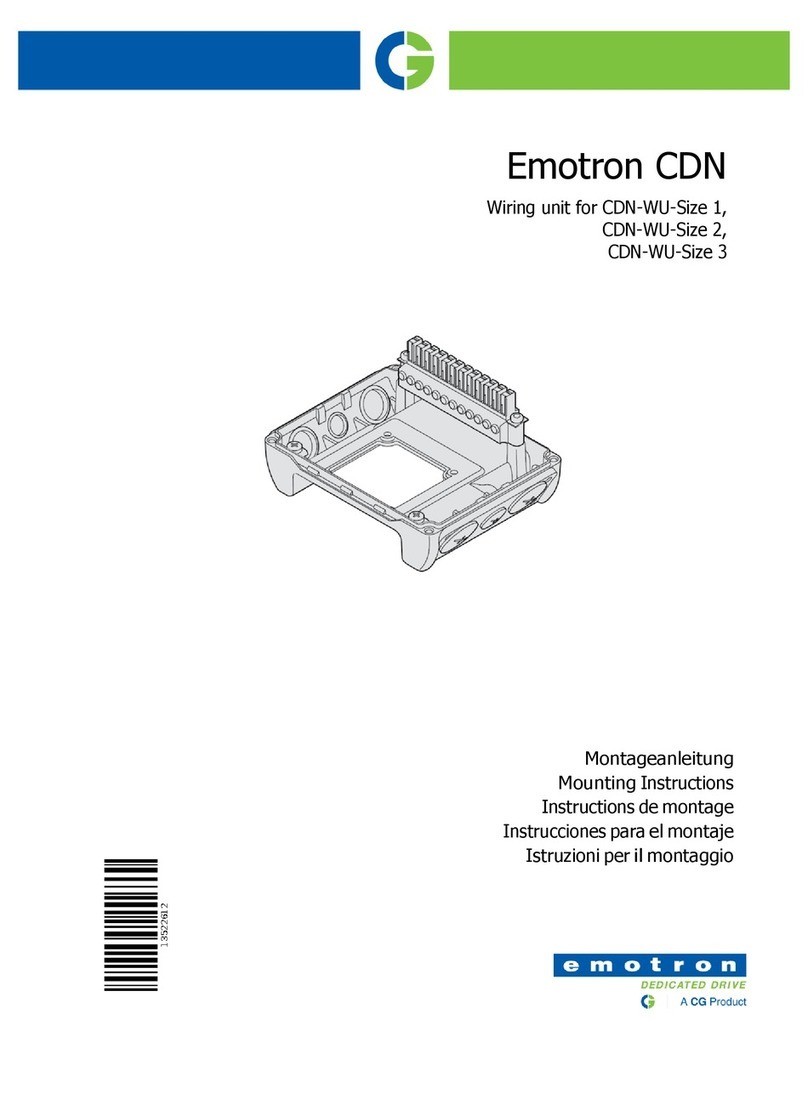
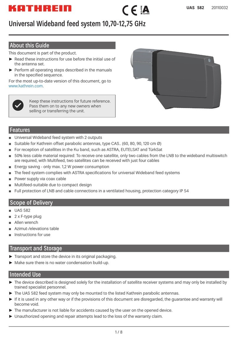
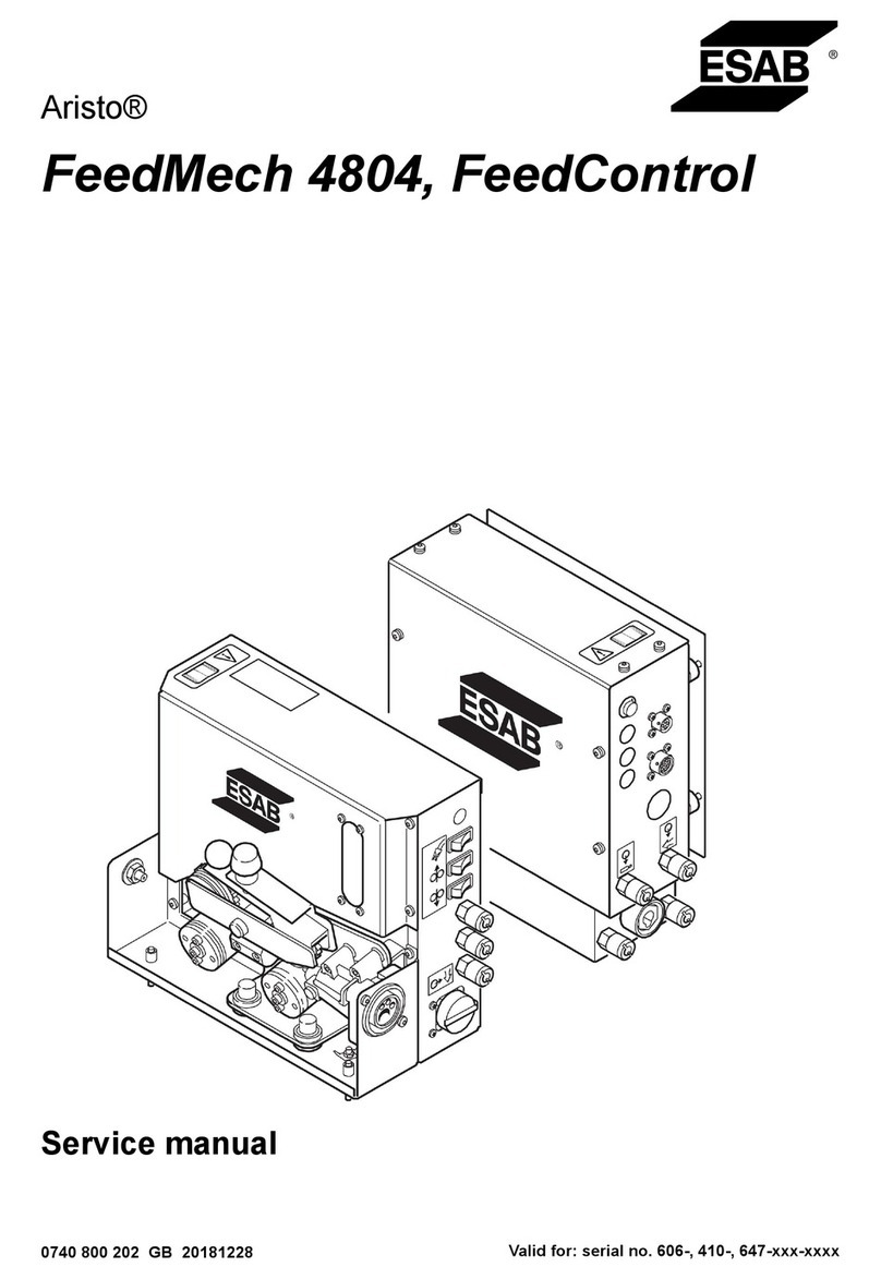
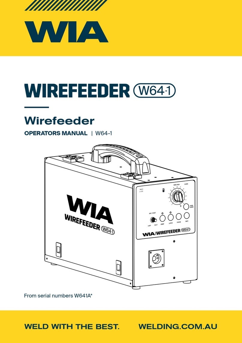
Comparc MM 300-ES User manual

PM1379 REV. 0
E.12-08-2021
MM 300 - ES
DC ARC WELDING POWER SOURCE
WIRE FEEDER
PROCESSES
DESCRIPTION
CONSTANT VOLTAGE (CV).
MIG (GMAW).
DC TYPEOUTPUT.
SINGLE PHASE.
302-589
OWNER´S MANUAL
T M
OWNER´S MANUAL
GIVETHISMANUALTOTHEOPERATOR

TABLE OF CONTENTS
ARCWELDING SAFETYPRECAUTIONS.................................................................................i
SECTION 1 -- SAFETY SIGNALS AND WORDS .....................................................................1
SECTION 2 -- SPECIFICATIONS .............................................................................................1
SECTION 3 -- INSTALLATION .................................................................................................3
SECTION 4 -- FUNCTION OF CONTROLS .............................................................................7
SECTION 5 -- MAINTENANCE & TROUBLESHOOTING......................................................10
SECTION 6 -- ELECTRICAL DIAGRAM.................................................................................13
SECTION 7 -- PARTS LIST ....................................................................................................14

i
SAFETY PRECAUTIONS - READ BEFORE USING
WARNING
- DANGER! - Indicates a hazardous situation which, if not avoided, will result in death or serious injury. The possible hazards are shown
in the adjoining symbols or explained in the text
- Indicates a hazardous situation which, if not avoided, could result in death or serious injury. The possible hazards are shown in the
adjoining symbols or explained in the text.
- The symbols shown below are used throughout this manual to call attention to and identify possible hazards. When you
see the symbol, watch out, and follow the related instructions to avoid the hazard. The safety information given below is
only a summary of the more complete safety information found in the Safety Standards.
- Only qualified persons should install, operate, maintain, and
repair this unit.
- During operation, keep everybody, especially children, away.
ARC WELDING can be hazardous.
ELECTRIC SHOCK can kill.
Touching live electrical parts can cause fatal shocks or
severe burns. The electrode and work circuit is
electrically live whenever the output is on. The input
power circuit and machine internal circuits are also live
when power is on. In semiautomatic or automatic wire
welding, the wire, wire reel, drive roll housing, and all
metal parts touching the welding wire are electrically live. Incorrectly
installed or improperly grounded equiment is a hazard.
1.- Do not touch live electrical parts.
2.- Wear dry, hole-free insulating gloves and body protection.
3.- Insulate yourself from work and ground using dry insulating
mats or covers.
4.- Disconnect input power or stop engine before installing or
servicing this equipment.
5.- Properly install and ground this equipment according to this
Owner's Manual and national, state, and local codes.
6.- Turn off all equipment when not in use.
7.- Do not use worn, damaged, undersized, or poorly spliced cables.
8.- Do not wrap cables around your body.
9.- Ground the workpiece to a good electrical (earth) ground.
10.- Do not touch electrode while in contact with the work (ground)
circuit.
11.- Use only well-maintained equipment. Repair or replace damaged
parts at once.
12.- Wear a safety harness to prevent falling if working above floor
level.
13.- Keep all panels and cover securely in place.
ARC RAYS can burn eyes and skin;
NOISE can damage hearing.
Arc rays from the welding process produce intense heat
and strong ultraviolet rays that can burn eyes and skin.
Noise from some processes can damage hearing.
1.- Wear a welding helmet fitted with a proper shade of
filter (see ANSIZ49.1 listed in Safety Standards) to protect
FUMES AND GASES can be hazardous
to your health.
Welding produces fumes and gases. Breathing these
fumes and gases can be hazardous to your health.
1.- Keep your head out of the fumes. Do not breath the fumes.
2.- If inside, ventilate the area and / or use forced ventilation at the arc to
remove welding fumes and gases.
3.- If ventilation is poor, use an approved air-supplied respirator.
4.- Read the Material Safety Data Sheets (MSDSs) and the
manufacturer´s instruction for metal, consumables, coatings, and
cleaners.
5.- Work in a confined space only if it is well ventilated, or while wearing
an air-supplied respirator. Shielding gases used for welding can
displace air causing injury or death. Be sure the breathing air is safe.
6.- Do not weld in locations near degreasing, cleaning, or spraying
operations. The heat and rays of the arc can react with vapors to
form highly toxic and irritating gases.
7.- Do not weld on coated metals, such as galvanized, lead, or cadmium
plated steel, unless the coating is removed from the weld area, the
area is well ventilated, and if necessary, while wearing an air-
supplied respirator. The coatings and any metals containing these
elements can give off toxic fumes if welded.
FLYING SPARK AND HOT METAL can
cause injury
Chipping and grinding cause flying metal . As welds
cool, they can throw off slag.
1.- Wear approved face shield or safety goggles. Side shields
recommended.
2.- Wear proper body protection to protect skin.
your face and eyes when welding or watching.
2.- Wear approved safety glasses. Side shields recommended.
3.- Use protective screens or barriers to protect others from flash and
glade; warn others not to watch the arc.
4.- Wear protective clothing made from durable, flame- resistant mate
rial (wool and leather) and foot protection.
5.- Use approved ear plugs or ear muffs if noise level is high.
ii
CYLINDERS can explode if damaged.
Shieldinggas cylinders contain gas under high pressure.
If damaged, a cylinder can explode. Since gas cylinders
are normally part of the welding process, be sure to treat
them carefully.
1.- Protect compressed gas cylinders from excessive heat, mechanical
shocks, and arcs.
2.- Install and secure cylinders in an upright position by chaining them
to a stationary support or equipment cylinder rack to prevent falling
or tipping.
3.- Keep cylinders away from any welding or other electrical circuits.
4.- Never allow a welding electrode to touch any cylinder.
5.- Use only correct shielding gas cylinders, regulators, hoses, and
fittings designed for the specific application; maintain them and
associated parts in good condition.
6.- Turn face away from valve outlet when opening cylinder valve.
7.- Keep protective cap in place over valve except when cylinder is in
use or connected for use.
8.- Read and follow instructions on compressed gas cylinders, associated
equipment, and CGA publication P-1 listed in Safety Standards.
ENGINES can be hazardous.
WARNING
ENGINE EXHAUST GASES can kill.
Engines produce harmful exhaust gases.
1.- Use equipment outside in open, well-ventilated
areas.
2.- If used in a closed area, vent engine exhaust outside and away from
any building air intakes.
ENGINE FUEL can cause fire or
explosion.
Engine fuel is highly flammable.
1.- Stop engine before checking or adding fuel.
2.- Do not add fuel while smoking or if unit is near any sparks or open
flames.
3.- Allow engine to cool beforefueling. If possible, check and add fuel
to cold engine before beginning job.
4.- Do not overfill tank - allow room for fuel to expand.
5.- Do not spill fuel. If fuel is spilled, clean up before starting engine.
MOVING PARTS can cause injury.
Moving parts, such as fans, rotors, and belts can cut
fingers and hands and catch loose clothing.
1.- Keep all doors, panels, covers, and guards closed
and securely in place.
2.- Stop engine before installing or connecting unit.
3.- Have only qualified people remove guards or covers for maintenance
and troubleshooting as necessary.
4.- To prevent accidental stating during servicing, disconnect negative
(-) battery cable from battery.
5.- Keep hands, hair, loose clothing, and tools away from moving parts.
6.- Reinstall panels or guards and close doors when servicing is finished
and before starting engine.
SPARKS can cause BATTERY GA-
SES TO EXPLODE; BATTERY ACID
can burn eyes and skin.
Batteries contain acid and generate explosive gases.
1.- Always wear a faceshield when working on a battery.
2.-Stopenginebeforedisconnectingorconnectingbattery
cables.
3.- Do not allow tools to cause sparks when working on a battery.
4.- Do not use welder to charge batteries or jump start vehicles.
5.- Observe correct polarity (+ and -) on batteries.
WELDING can cause fire or explosion.
Sparks and spatter flyoff from theweldingarc. The flying
sparks and hot metal, weld spatter, hot workpiece, and
hot equipment can cause fires and burns. Accidental
contact of electrode or welding wire to metal objects can
cause sparks, overheating, or fire.
1.- Protect yourself and others from flying sparks and hot metal.
2.- Do not weld where flying sparks can strike flammable material.
3.- Remove all flammables within 35ft (10.7 m) of the welding arc. If
this is not possible, tightly cover them with approved covers.
4.- Be alert that welding sparks and hot materials from welding can
easily go through small cracks and openings to adjacent areas.
5.- Watch for fire, and keep a fire extinguisher nearby.
6.- Be aware that welding on a ceiling, floor, bulkhead, or partition can
cause fire on the hidden side.
7.- Do not weld on closed containers surch as tanks or drums.
8.- Connect work cable to the work as close to the welding areas as
practical to prevent welding current from traveling long, possibly
unknown paths and causing electric shock and fire hazards.
9.- Do not use welder to thaw frozen pipes.
10.- Remove stick electrode from holder or cut off welding wire at
contact tip when not in use.
11.- Wear oil-free protective garments such as leather gloves, heavy
shirt, cuffless trousers, high shoes, and a cap.

STEAM AND PRESSURIZED HOT
COOLANT can burn face, eyes, and
skin.
The coolant in the radiator can be very hot and under
pressure.
1.- Do not remove radiator cap when engine is hot. Allow engine to cool.
2.- Wear gloves and put a rag over cap area when removing cap.
3.- Allow pressure to escape before completely removing cap.
- Additional Symbols For Installation, Operation, And Maintenance
NOISE can damage hearing.
Noise from some processes or equipment can damage hearing.
- Wear approved ear protection if noise level is high.

FALLING EQUIPMENT can injure
-Use lifting eye to lift unit and properly installed
accessories only, NOT gas cylinders. Do not
exceed maximum lift eye weight rating (see
Specifications).
-Use equipment of adequate capacity to lift and support unit.
-If using lift forks to move unit, be sure forks arelong enough to extend
beyond opposite side of unit.
-Keep equipment (cables and cords) away from moving vehicles when
working from an aerial location.
OVERUSE can cause OVERHEATING
-Allow cooling period; follow rated duty cycle.
-Reduce current or reduce duty cycle before starting to
weld again.
-Do not block or filter airflow to unit.
STATIC (ESD) can damage PC boards.
-Put on grounded wrist strap BEFORE handling boards or parts.
-Use proper static-proof bags and boxes to store, move, or ship PC boards.
ARC WELDING can cause interference.
-Electromagnetic energy can interfere with sensitive
electronic equipment such as microprocessors, computers,
and computer-driven equipment such as robots.
-Be sure all equipment in the welding area is
electromagnetically compatible.
- To reduce possible interference, keep weld cables as short as possible,
close together, and down low, such as on the floor.
-Locate welding operation 100 meters from any sensitive electronic
equipment.
-Be sure this welding machine is installed and grounded according to this
manual.
-If interference still occurs, the user must take extra measures such as
moving the welding machine, using shielded cables, using line filters, or
shielding the work area.
-Read and follow all labels and the Owner’s Manual carefully before installing, operating, or servicing unit.
Read the safety information at the beginning of the manual and in each section.
- Definitions
iii

PM1379
1
SECTION 1 SAFETY SIGNALS AND WORDS
IMPORTANT: Statements identify special instructions necessary for the most efficient
operationofthisequipment.
WARNING WARNINGstatementsidentifyproceduresorpracticeswhichmustbefollowedto
avoid seriuos personal injury or loss of life.
CAUTION CAUTIONstatementsidentifyproceduresorpracticeswhichmustbefollowedto
avoid minor personal injury or damage to this equipment.
Thefollowingsafetyalertsymbolandsignalwordsareusedthroughoutthismanualtocallattentiontoand
identifydifferentlevelsofhazardandspecialinstructions.
SECTION 2 SPECIFICATIONS
Rated Weld Amperage
Duty Cycle
Wire Diameter
Length
Cooling System
250 Amperes
60 % With CO2
.035" to .045" ( 0.89 to 1.14 mm)
10 ft. (3 m.)
Air
RECOMMENDED GUN
FIGURE2-1 VOLT-AMPERECURVES.
2-1 VOLT-AMPERE CURVES.
Thevolt-amperecurvesshowthe
minimumandmaximumvoltage
andamperageoutputcapabilities
ofthe welding source. Curves of
othersettingsfallbetweencurves
shown.
A=HIGHRANGE
B= LOW RANGE
DCAMPERES
DCVOLTS
Nominal
60% Continue
100% Maximum
40% A kW
230V ac 43
460V ac 21.5
575V ac 17.2
Powersupply Open circuit
voltage
InputatRated load,
60Hz
OutputCurrent
Duty cycle Welding
voltage range
Currentrange Weight
lb (kg)
250A @26.5V dc 190A @23.5 Vdc 300A @28V dc 30 A - 300A
Dimensions
in (mm)
10- 28V dc 32V dc 7.7 Heigh:31.2(794)
Width: 14.2(362)
Length:38(965)
Net:264.5(120)
Ship.: 271(123)

PM1379 2
Definition
Duty Cycle is percentage of 10
minutes that unit or gun can weld
at ratedloadwithoutoverheating.
FIGURE 2-2 DUTYCYCLECURVES.
60% DutyCycle At 250 Amperes
MINUTES 6 Minutes Welding 4 Minutes Resting
2-2 DUTY CYCLE.WELDINGLONGERTHANRATEDDUTYCYCLEcandamageunitandvoidwarranty.
Do not weld at rated load longer than shown below.
CAUTION
20
100
150
200
250
300
35 60 90
40 70
100 %
30 50
Duty Cycle
Rated output
W
e
l
d
A
m
p
e
r
e
s
80

PM1379
3
3-2. POSITIONING JUMPER LINKS.
3-1. GUN INSTALLATION
FIGURE 3-1. GUN INSTALLATION
1 MIG GUN OPENING.
2 TRIGGER RECEPTACLE.
3 WIREFEEDERMECHANISM.
4 LOCKING KNOB.
5GUNEND.
Loosen locking knob and insert gun end through access hole into gun adapter. Tighten locking knob.
6 GUNTRIGGER PLUG.
Insert plug into receptacle, and tighten threated collar.
Check input voltage available at site.
1.- Jumper Links Access Door
Open door.
2.- Jumper Link Label
Check label - only one is on unit.
3.- Input Voltage Jumper Links
Movejumperlinkstomatchinputvoltage.
Close and secure access door.
DCTP0022
460 VOL TS
230 VOLTS
575 VOLTS
JUMPER LINKSLOCATION
L1
L1
L1L2
L2
L2
1
2
3
DCTP0022
460 VOLT S
230 VOLTS
575 VOLTS
JUMPER LINKSLOCATI ON
L1
L1
L1
L2
L2
L2
SECTION 3 INSTALLATION
3
4
TURN TO TIGHTEN
OR LOOSEN

PM1379 4
3-4 CONNECTING INPUT POWER
3-3 ELECTRICAL SERVICE GUIDE
220 440
45 22.5
50 25
60 30
8 12
127
(39) 206
(63)
10 12
Max Recommended Input Conductor Length In Feet (Meters)
Min Grounding Conductor Size In AWG 4
Input Voltage
Input Amperes (A) At Rated Output
Max Recommended Standard Fuse Rating In Amperes 1
Time-Delay Fuses 2
Normal Operating Fuses 3
Min Input Conductor Size In AWG 4
Installation must meet all National
and Local Codes - have only qualified
persons make this installation.
Disconnect and lockout/tagout input
power before connecting input
conductors from unit.
Always connect green or green/
yellow conductor to supply
grounding terminal first, and never
to a line terminal.
See rating label on unit and check input
voltage available at site.
1 Plug (NEMA Type 6-50P)
2 Receptacle
[NEMA Type 6-50R (Customer Supplied)]
3 Input Power Cord.
Connect directly to line disconnect device if
hard wiring is required.
4 Disconnect Device (switch shown in
the OFF position)
5 Disconnect Device Grounding Terminal
6 Disconnect Device Line Terminals
7 Green Or Green/Yellow Grounding
Conductor
8 Black and White Input Conductor (L1
and L2)
Connect green or green/yellow grounding
conductor to disconnect device grounding
terminal first.
Connect input conductors L1 and L2 to
disconnect device line terminals.
9 Over-Current Protection
Select type and size of over-current
protection using Section 3.3 (fused
disconnect switch shown).
Connect plug to receptacle if hard wiring
method is not used.
Close and secure door on disconnect
device.
Remove lockout/tagout device, and place
switch in the On position.

PM1379
3-5 WIRE WELDING INSTALLATION.
1
2
7
4
6
5
3
1.- WIRE SPOOL / REEL.
2.- WELDING WIRE.
3.- GUN END.
4.- PRESSURE ADJUSTMENT KNOB.
5.- DRIVE ROLL.
6.- INLET WIRE GUIDE.
7.- GUN CONDUIT CABLE. Try to keep straight gun
conduit when you going to install welding wire.
8Wood
5
9
67
4
3
1
2
FUERA
INTERRUPTOR
DE LINEA
DENTRO
1.- PRESSURE GEAR ASSEMBLY.
Release pressure knob.
2.- PULL AND HOLD WIRE. Cut off end.
3.-PUSHWIRETHROUGHGUIDESINTO
GUN. Continue holding wire.
4.- CLOSE AND LATCH pressure gear
assembly and let go wire. Install gun into
receptacle and tighten locking screw.
5.- REMOVE CONTACT TIP and nozzle.
6.- PLACE SWITCH in "ON" position.
7.- PRESS TRIGGER until wirecomes out
of MIG gun.
Reinstall contact tip and nozzle on MIG
gun.
8.-FEEDWIRETOCHECKDRIVEROLLS
pressure, tighten knob enough to prevent
slipping.
9.-CUT OFFENDOF WIRE.
Close and latch door.
Hold Wire Tightly to Keep It From Unraveling.
FIGURE3-5.WIREINSTALLATION.
3
POWER
5

PM1379 6
Obtaingascylinderandchaintorunninggear,wall,orother
stationarysupportsocylindercannotfallandbreakoffvalve.
1.-CAP.
2.-CYLINDERVALVE.
Removecap,standtosideofvalve,andopenvalveslightly.
Gasflowblowsdustanddirtfromvalve.Closevalve.
3.-CYLINDER.
4.-REGULATOR/FLOWMETER.
5.-GASHOSECONNECTION.
6.-FLOWADJUST.
Typical flowrate is 20 cfh ( Cubic Feetper Hour).
FIGURE3-6SHIELDEDGASCONNECTIONS.
1
2
3
6
5
4
3-6 SHIELDED GAS CONNECTIONS.
WARNING SEE SAFETY SIGNAL AT THE BEGINING THIS MANUAL
28.5, 15.8mm (1-1/8",5/8")
ToolsNeeded
3-7 SPOOL WIRE INSTALLATION.
For 8" and 12" (standard) wire spools
turn unit off anddisconnect it.
1.-Hubspool.
2.- Pin of Hub spool.
3.- Wire spool / Reel.
4.- Hud spool cap.
Turn thehub spool cap clockwise
andremove it.Install thewirespool, be
sure the hub spool´s pin enters oneof the
holesof the wire spool. Reinstall the hub
spool cap.
1
2
3
4
FIGURE3-7SPOOLWIREINSTALLATION.

PM1379
V
F-0371
REV. 0
F-0372
REV. 0
FIGURE 4-3.FRONTOFTHEMACHINE
MEASUREMENT (AMP /
PPM)
SPEEDADJUSTMENT
SPOT CONTROL
7
BURNBACK
TIME CONTROL
SECTION 4 FUNCTION OF CONTROLS
CAUTION SEE SAFETY SIGNAL AT THE BEGINING
THIS MANUAL
FIGURE 4-1 SAFETYEQUIPMENT.
1-InsulatingGloves.
2- Safety Glasses With Side Shields.
3- Welding Helmet. Wear dry insulating gloves,
safety glasses with sideshields, and a welding helmet
withacorrectshadeof filter(seeANSI Z49.1).
321
14.3mm,19mm
(9/16", 3/4")
-
+
-
+
GUN
POLARITY
REVERSEPOLARITY
(ELECTRODEPOSITIVE) STRAIGHTPOLARITY
(ELECTRODENEGATIVE)
FIGURE4-2 GUNPOLARITY.
GUNTRIGGER
RECEPTACLE
INPUT POWER SWITCH RECEPTACLERC14
FOR SPOOL GUN
GUN
CONNECTOR
OUTPUT
WORKCABLE
VOLTAGE
ADJUSTMENT
VOLTMETER
AMMETER/
SPEEDOMETER
SELECTOR
SWITCH FOR
SPOT
ToolsNeeded

PM1379
FIGURE4-6. INPUTPOWERSWITCH
8
VOLTAGE ADJUSTMENT CONTROL.
With this knob the same arc voltage (PRESET) that is displayed on
the '' voltmeter '' is selected when the output of the machine is not
operating
FIGURE 4-7. VOLTAGE ADJUSTMENT CONTROL
FIGURE 4-8 WIRESPEEDCONTROL
Wire Speed Control
Use control to select a wire feed speed. As Voltage switch setting increases, wire speed
range also increases. The numbers around the control are not a wire feed speed and are
for reference only
Gun Connector. Connect gun into gun
receptacle until bottom and be sure be
perfectlytighten.
FIGURE 4-4 GUNCONNECTOR.
GUN TRIGGER
GUN
FIGURE 4-5 RECEPTACLE RC14.
RC14 RECEPTACLE. This connector is a receptacle for a gun spool. To connect thisreceptacle,
align keyway, insert plug, and tighten threaded collar.
Socket Information:
SOCKET A: 24 Volts AC, 10 Amperes, 60 Hz., respect G socket (common).
SOCKET B: Contact closure to pin A completes 24 Volts AC contactor control circuit
SOCKET G: Circuit common for 24 and 120 VAC circuit.
SOCKET I: 120 VAC respect socket G.
SOCKET J: Contact closure to pin I completes 120 VAC contactor control circuit.
SOCKET K: Common .
REMAININGSOCKETSARENOTUSED.
INPUT POWER SWITCH.Placing the power switch in ON
position energizes the welding power source. Placing the
power switch in the OFF position the unit shuts down.
V
SPEED
VOLTAGE

PM1379
9
FIGURE 4-10. SELECTOR OF SPOT/BURNBACK
BURNBACK. The time control for the wire trimmer allows to select the time that the electrode remains
energized after the feeding of the wire has been suspended.
The appropriate time is that which allows the electrode to be free of the weld bead. If the time of the
trimmer is very long the electrode can be fused with the torch contact tube. Turning the knob of the
control clockwise increases the time from 0 to 0.25 seconds. The scale is calibrated in percentages
and does not indicate the operating time of the wire cutter.
FIGURE 4-11. SPOT
CONTROL OF SPOT TIME. This control allows you to adjust the tapping time (duration of the
operation or welding interval) from 0.5 to 4 seconds. Turning the knob clockwise increases
the time. The scale of the control is calibrated in percentage and does not indicate the interval
time.
FIGURE 4-12. BURNBACK
FUNCTION SELECTOR TIP / TRIM. Placing the switch in the "PUNTEE / TRIM" position activates
two functions:
1.- Dotting: Welding by time intervals, the duration of each interval (from when the torch trigger
is pressed) will depend on the position pre-set in the control of the spot time.
2.- Burnback: As soon as the torch trigger is deactivated, the wire feed is suspended while the
electrode (wire) is kept energized for a period of time (established by the trimming control).
DIGITAL METERS
DIGITAL VOLTMETER
When the trigger of the gun is not activated the preset voltage value (Preset) is displayed.
When the trigger of the gun is activated, the real voltage value that exists between the output terminals of the machine is shown, which depending
on the situation, can open circuit, arc voltage or short circuit
AMPERMETER/DIGITALSPEEDMETER
This meter has two functions to select by means of the switch located on the right of it:
1.- DIGITAL AMPERMETER. During the welding process, the value of the output current is shown. When it is extinguished, the last value shown
is retained for approximately 4 seconds and then the display goes off (it remains off while the current is zero).
2.- DIGITAL SPEEDOMETER. The value of the wire feed speed is shown during the welding process. When the arc current is extinguished,
the last displayed speed value is retained for approximately 4 seconds and then the preset or desired speed (Preset) value is displayed and
remains so as long as the current is zero.
FIGURE 4-9. DISPLAY
SPOT
SPOT/BURNBACK
SPOT
BURNBACK

PM1379 10
Readjust
Controls And
begin welding
Do a Weld
Test
Adjust
Controls
Turn On Unit And
supply gas
(If Applicable)
Put On Personal
Safety Equipment
Install &
Connect
Equipment
FIGURE 4-12 SECUENCE FOR SOLID WIRE AND FLUX CORED ARC WELDING.
FIGURE4-13. SECUENCEFORALUMINUMWIREWELDING.
Put On safety
equipment.
Adjust drive roll
Pressure at
minimum
Adjust hub
tension at
minimum
Readjust controls
and beging
welding
Do a test weld
Install & Connect
equipment using
"U" rolls
Turn on
equipment and
adjust gas at 30cfh
Adjust controls and
keep away GUN
from work piece.
FIGURE5-1.CHANGINGCONTACTTIP.
Turnoff anddisconnect theunit.
1.- NOZZLE.
2.-CONTACTTIP.Cut wire remaining
ofthecontacttip,removeNozzle,remove
the contact tip and install one new.
Reinstallnozzle.
ToolsNeeded
2
1
5-1 ROUTINE MAINTENANCE.
TIME
Replace unreadable Labels ; Clean And Tighten Weld Terminals; Tape Or Replace Cracket
Weld Cable; Replace Cracket Parts (such as 14-Pin Cord,Gas Hose, Gun Cable).
Each3Months
Each6Months
MAINTENANCE
Blow Out Or Vacuum Inside; During Heavy Service Clean Monthly; Clean Drive Rolls.
5-2 CHANGING CONTACT TIP.
SECTION 5 MAINTENANCE &
TROUBLESHOOTING
WARNING SEE SAFETY PRECAUTIONS SECTION

PM1379
11
5-3. OVERLOAD PROTECTION.
Disconnect the unit from the power supply
before removing the left side cover.
1.- Left cover.
2.- Fuse F4.
3.- Fuse F5.
If fuses F4 and F5 are open, there will be no
energy in the fan motor.
4.- Fuse F6.
Protect at control transformer from overload, if F6
open, output unit stops.
5.- 10 A fuse. F1.
ThefuseF1protectsthecontrolcardPC3against
shortcircuitsoroverloadsproducedintheremote
receptacle14.
6.- Fuse F2
7.- Fuse F3
ThefusesF2andF3protectsthecontrolcardPC1
against short circuits.
Usingincorrectfusesmaydamagetheunitor
the power supply network. Use only original
fuses (same type, size and rating).
Figure 5-2 Overload protection.
Replacingafuse.
1.-Removetheleftsidecover.
2.- Replace theopen or damaged fuse.
3.-Reinstallthesidecover.
5
6
7
1
2
3
4

PM1379 12
5-4 TROUBLESHOOTINGS.
No weld output; wire doesnot feed; fan
doesnot run.
Table5-1.WeldingTrouble
RECOMENDEDACTION
TROUBLE
Lowweldoutput.
No weld output; wiredoesnot feed; fan
motor continuesto run.
Noweldoutput;wirefeeds.
Straightenguncableand/orreplacedamagedparts.
Adjustdriverollpressure.
Changetopropergroove.
---------------- ------------------ -------------------- ---------------
Replacecontact tipif blocked
Cleanorreplacewire inletguideorlinerif dirtyorplugged.
Replacedriverollorpressurebearingifwornorslipping.
Secureguntriggerpluginreceptacle.
Checkandreplace motorfuseF1.
Check and clearany restrictionsat drive assembly and liner.
HavenearestFactoryAuthorizedServiceStation/ServiceDistributorcheckdrive
motor.
RECOMMENDEDACTIONTROUBLE
Table5-2.WireDrive/GunTrouble
Wirefeedingstopsduringwelding
Securepowercordpluginreceptacle.
Replacebuildingline fuseorreset circuit breakerif open.
Secureguntriggerpluginreceptacle.
Power switch in On position.
HaveFactoryAuthorizedServiceStation/ServiceDistributorcheckallboard
connections andshut downPC1 board.
Connect work clamp to get goodmetal to metal contact.
Replacecontact tip.
Checkforproperconnectionsatpolaritychangeoverboard.
Connectunit toproperinputvoltageorcheckforlowlinevoltage
Placevoltageswitchindesiredposition.

PM1379
13
SECTION 6. ELECTRICAL DIAGRAM
C4
RC4-7 T ERMOSTH AT
RC3-5
RC1-3
RC4-8 GND
RC4-6 +15V
RC1-1
R5
RC2 / PLG2
RC1 / PLG1
PC1
POSITIVE
TP1
2 0V3
4 0V6
2 0V3
1
2
3
4
L1
L2
GND
C5
NEGATIVE
RC3-3 +VFB
RC3-2 0V
RC3-6 -VFB
FM
NOT :E
“T "WISTED
RC4-1 AMP / SPEED
RC1 / PLG5
PC2
RC1-2
5
6
+
C3
T1
SCR1
SCR2
RC2-4
WHITE
RC2-2
RED
RC2-3
WHITE
RC2-1
RED
A
B
C
D
2
RC1-A +24V
1
RC1-B GND
R1
RC4-5
THERMAL P.
RC1-1
RC1-6
RC1-2
RC1-5
RC1-3
RC4-2 IFB
RC4-4 VFB
RC4-3 +24V
43
16
8
10
41
40
20
21
32
31
30
22
23
25
24
THERMAL PROTECTION
OF RECTIFIER
COM ANDM
RC3 / PLG3
RC4 / PLG4
CONTROL MM300 ES
REMOTE SIGNAL
VOLTS/AMPER METER
RC1, RMT 4P
C2
C1
DIGITAL
18V . .a c
RC3-4 +5V
RC1-F SPEED REF (+8V)
RC1-G COM SPEED
RC1-E GND R2
35
34
33
SPEED CONTROL
S1-A
43
S1-B
Z1
GS1
VALVE
RC4-F 24 Vc.a.
RC4-B CR1 PCB
36
37
33 Vac
33 Vac
18V . .a c
230 a cV . .
RC3 / PLG7
RC1 / PLG6
PC3
RC4-E
RC4-C
RC4 / PLG8
MOTOR CONTROL
43
F1
10 Amp.
24V . .a c
M1 MOTOR
RC4-G M +
RC4-H M -
38
39
RC3-A
RC4-A CONTACTOR
RC3-E
RC4-10 +10V/REF
RC4-9 COM ANDM
RC3-F
RC3-D
RC3-C
26
27
RC5-F +24V
RC5-L MIN R3
45
44
BURNBACK
TIME
RC5-H
RC5-E
RC5-D
RC5-C
RC5-K
RC5-A SPOT
RC5-J GND49
48
S3
RC5-B MIN
RC5-G +24V
R4
47
46
SPOT TIME
51
50
54
53
52 MAX
1
4
43
12
8
9
8
10
43
14
15
19
RC5 / PLG9
PC4
TIMER
A
RC2, RMT 14
B
K
G
CR1
4356
55
43
43
SPOOL GUN
SPOOL GUN
CR1
S2
37
MAX
MAX
MAX
HDR 2x3P
HDR 2x5P
TERMINALS P/PCB
HDR 1x3P HDR 2x2P
E8
E7
E9
E5
E6
(R )ED
( / )GREEN BLACK
COIL CR1 PCB
HABILIT M1
+24V
SPOT CONTROL
COMUN
R6
MEANING
2
3
T2
43
SPOT
7 4
A B
C6 C7 C8
RC3-1 +IFB
LEM
7
11
13
28
DE-0190
REV. 0
18V . .a c
T2
2 0 V3 AC
TO PRIMARY
CONNECTIONS
1
3
REMOTE SIGNAL
T ERMOSTH AT
T1
PRIMARY
CONECTIONS
MM 300 ES
F4
F5
F2
F3
575V
5
6
F6

PM1379
SECTIÓN 7. PARTS LIST
14
Ref. I.D. Quantity
1 PC1802 Chasis. 1
2 Front assembly (fig. 7-2) 1
3 PR0815 SR1 Main rectifier. Consisting of: 1
MT08386 SCR1, 2 Tyristor 2
4 PR0587 Wheel, rear assembly. 1
5 PT3684 T1 Transformer, main assembly. Consisting of: 1
PB2412 Coil 1
PC1807 Head core 1
PN0161 Core 1
6 MT08939 T2 Transformerof control. Consisting of: 1
7 PE0706 Z1 Stabilizer assembly. Consisting of: 1
PB2044 Coil 1
PN0160 Core 1
PC1806 Head core 1
8 PC3352 Cover 1
9 PC3351 Mobile covel 1
10 PC1803 Panel, cover complement 1
11 MV01110 Fan motor 1
12 PB0967 C3 Capacitor bank. Consisting of: 1
MC00698 Capacitor 27000uF, 50V 5
13 MV00768 GS1 Válve solenoid 1
14 PT2255 PC1 Pc control board 1
15 PT3636 PC3 Pc control of motor 1
16 PT3605 PC4 Pc burnback 1
17 PM0406 M1 Wire feeder mechanism. (fig. 7-3) 1
18 MT08758 CT1 Sensor Hall 1
19 PB1925 Baffle 1
20 PR0464 Bracket, bottle retainer 1
21 Overload protection . Consisting of:
MF02310 F1 Fuse 10A 1
MF02311 F2, F3 Fuse 2A 2
MP00014 Fuse holder 15A 250V 3
22 MR05740 Wheel, rotatory front 2
23 MR09534 CR1 Relay 2P2T 24 Vac. 1
24 PT2923 Cover rear 1
25 PT3612 Terminal, input connections 1
26 PS2180 Gun support 1
27 PP3658 Spool wire 1
28 MR01495 Resistor 5 ohm 300W 1
29 PT0923 Terminal power, black.
30 PT0924 Terminal power, red 1
31 MF02313 F4, F5 Fuse, 2.5A 2
MB05896 Fuse base 1
32 MF02311 F6 Fuse 2A 1
MB05897 Fuse base 1
Part No. Description

PM1379
15
FIGURE 7-1 MAIN ASSEMBLY.
9
10
2
2
2
4
8
2
6
1
6
1
5
1
9
1
2
1
2
8
2
5
3
7
29
5
1
7
18
23
2
7
21
2
4
1
1
1
3
6
1
4
2
0
3
1
3
2
30
Table of contents
Popular Wire Feeder manuals by other brands

RNA
RNA SLC 500-200 operating instructions

Oerlikon
Oerlikon DMU P400 Instruction for operation and maintenance

Shibuya Hoppmann
Shibuya Hoppmann FR-20 Installation & maintenance manual

Oerlikon
Oerlikon DV 4004 CTLW Safety instruction for use and maintenance

Miller
Miller S-74 MPa Plus owner's manual

PROFAX
PROFAX PX20-TIG owner's manual