COMPRO IP540 User manual

Network Camera
IP540
IP540P
IP570
IP570P
Model No.
V2-111102

Copyright
© 2011 Compro Technology, Inc. All rights reserved.
Trademark
Compro Technology is the registered trademarks of Compro Technology Inc. Seedonk
and Seedonk Messenger are registered trademarks of Seedonk Inc. Apple, Mac and Mac OS are
trademarks of Apple Inc., registered in the U.S. and other countries. Seedonk and Seedonk Messenger
are registered trademarks of Seedonk Inc. SD, SDHC, microSDHC Logos are trademarks of SD-3C, LLC.
All other company and product names mentioned in this document are registered trademarks of the
respective companies.
Restriction
No part of this document may be copied or reproduced in any form or by any means without the prior
written consent of Compro Technology, Inc.
Disclaimer
Compro Technology makes no warranties with respect to this documentation and disclaims any implied
warranties of merchantability, quality, or fitness for any particular purpose. The information in this
document is subject to change without notice. COMPRO reserves the right to make revisions to this
publication without obligation to notify any person or entity of any such changes.
Revision History
2011/11/02 Updated power supply information
2011/03/31 Marked features that currently are not available on IP570(P)
2011/01/20 Original 2.0 version
Compro Technology Inc.
www.comprosecurity.com
Tel. +886 2 2918 0169, Fax +886 2 2915 2389
3F, No.12, Alley 6, Lane 45, Pao Shin Road,
Hsintien District, New Taipei City 231, Taiwan

Contents
<頁頁頁頁頁頁>
Contents
01
Contents
Chapter 1: Important Notices . . . . . . . . . . . . . . . . . . . . . . . . . . . . . . . . . . . . . . . . . . . . . . . . . . . . . .1-1
Regulatory Notice . . . . . . . . . . . . . . . . . . . . . . . . . . . . . . . . . . . . . . . . . . . . . . . . . . . . . . . . . . 1-1
Operation Safety . . . . . . . . . . . . . . . . . . . . . . . . . . . . . . . . . . . . . . . . . . . . . . . . . . . . . . . . . . . 1-1
About this Manual . . . . . . . . . . . . . . . . . . . . . . . . . . . . . . . . . . . . . . . . . . . . . . . . . . . . . . . . . . 1-2
Conventions in this Manual . . . . . . . . . . . . . . . . . . . . . . . . . . . . . . . . . . . . . . . . . . . . . . . . . . . . 1-2
Chapter 2: Product Overview. . . . . . . . . . . . . . . . . . . . . . . . . . . . . . . . . . . . . . . . . . . . . . . . . . . . . . . 2-1
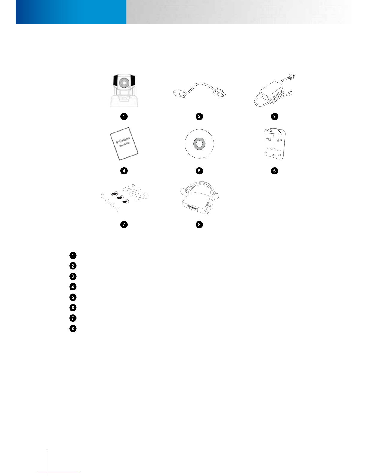
Package Contents . . . . . . . . . . . . . . . . . . . . . . . . . . . . . . . . . . . . . . . . . . . . . . . . . . . . . . . . . . 2-1
IP540(P) . . . . . . . . . . . . . . . . . . . . . . . . . . . . . . . . . . . . . . . . . . . . . . . . . . . . . . . . . . . . . .2-1
IP570(P) . . . . . . . . . . . . . . . . . . . . . . . . . . . . . . . . . . . . . . . . . . . . . . . . . . . . . . . . . . . . . .2-2
Features . . . . . . . . . . . . . . . . . . . . . . . . . . . . . . . . . . . . . . . . . . . . . . . . . . . . . . . . . . . . . . . .2-3
IP540(P) Full Feature List . . . . . . . . . . . . . . . . . . . . . . . . . . . . . . . . . . . . . . . . . . . . . . . . . . . .2-3
IP570(P) Full Feature List . . . . . . . . . . . . . . . . . . . . . . . . . . . . . . . . . . . . . . . . . . . . . . . . . . . .2-4
Application Diagram . . . . . . . . . . . . . . . . . . . . . . . . . . . . . . . . . . . . . . . . . . . . . . . . . . . . . . . .2-5
Camera Layout . . . . . . . . . . . . . . . . . . . . . . . . . . . . . . . . . . . . . . . . . . . . . . . . . . . . . . . . . . . . 2-6
LED Status Indicator . . . . . . . . . . . . . . . . . . . . . . . . . . . . . . . . . . . . . . . . . . . . . . . . . . . . . . . . . 2-7
Chapter 3: Installation . . . . . . . . . . . . . . . . . . . . . . . . . . . . . . . . . . . . . . . . . . . . . . . . . . . . . . . . . . . 3-1
Connecting the Cables . . . . . . . . . . . . . . . . . . . . . . . . . . . . . . . . . . . . . . . . . . . . . . . . . . . . . . .3-1
Connecting Using PoE Function . . . . . . . . . . . . . . . . . . . . . . . . . . . . . . . . . . . . . . . . . . . . . . . . . 3-2
Wireless Connection. . . . . . . . . . . . . . . . . . . . . . . . . . . . . . . . . . . . . . . . . . . . . . . . . . . . . . . . . 3-3
Mounting on the Wall or Ceiling . . . . . . . . . . . . . . . . . . . . . . . . . . . . . . . . . . . . . . . . . . . . . . . . . 3-4
Installing Camera Software . . . . . . . . . . . . . . . . . . . . . . . . . . . . . . . . . . . . . . . . . . . . . . . . . . . .3-5
Running the iWizard Setup Utility . . . . . . . . . . . . . . . . . . . . . . . . . . . . . . . . . . . . . . . . . . . . . . 3-6
Running the iWizard Installer (for IP570 / 570P) . . . . . . . . . . . . . . . . . . . . . . . . . . . . . . . . . . . .3-12
Installing ComproView . . . . . . . . . . . . . . . . . . . . . . . . . . . . . . . . . . . . . . . . . . . . . . . . . . . . 3-17
Chapter 4: Accessing the Camera . . . . . . . . . . . . . . . . . . . . . . . . . . . . . . . . . . . . . . . . . . . . . . . . . . . . 4-1
Viewing Live Video Stream. . . . . . . . . . . . . . . . . . . . . . . . . . . . . . . . . . . . . . . . . . . . . . . . . . . . . 4-1
Accessing via PC Web Browser . . . . . . . . . . . . . . . . . . . . . . . . . . . . . . . . . . . . . . . . . . . . . . . . . .4-2
Accessing via iPhone/Smartphone . . . . . . . . . . . . . . . . . . . . . . . . . . . . . . . . . . . . . . . . . . . . . . .4-4
Accessing via 3GPP Mobile Phone . . . . . . . . . . . . . . . . . . . . . . . . . . . . . . . . . . . . . . . . . . . . . . . . 4-5
Accessing via Seedonk IM Client (IP540 / 540P only) . . . . . . . . . . . . . . . . . . . . . . . . . . . . . . . . . . . .4-5
Chapter 5: Live View . . . . . . . . . . . . . . . . . . . . . . . . . . . . . . . . . . . . . . . . . . . . . . . . . . . . . . . . . . . .5-1
Page Layout - 540(P). . . . . . . . . . . . . . . . . . . . . . . . . . . . . . . . . . . . . . . . . . . . . . . . . . . . . . . . . 5-1
Page Layout - 570(P). . . . . . . . . . . . . . . . . . . . . . . . . . . . . . . . . . . . . . . . . . . . . . . . . . . . . . . . . 5-2
Icons on Live View Page . . . . . . . . . . . . . . . . . . . . . . . . . . . . . . . . . . . . . . . . . . . . . . . . . . . . . .5-3
Voice Communication . . . . . . . . . . . . . . . . . . . . . . . . . . . . . . . . . . . . . . . . . . . . . . . . . . . . . . .5-6
Chapter 6: Conguration . . . . . . . . . . . . . . . . . . . . . . . . . . . . . . . . . . . . . . . . . . . . . . . . . . . . . . . . . 6-1
Main Setup Page . . . . . . . . . . . . . . . . . . . . . . . . . . . . . . . . . . . . . . . . . . . . . . . . . . . . . . . . . . . 6-1
Video Settings . . . . . . . . . . . . . . . . . . . . . . . . . . . . . . . . . . . . . . . . . . . . . . . . . . . . . . . . . . . .6-2
Video Mode . . . . . . . . . . . . . . . . . . . . . . . . . . . . . . . . . . . . . . . . . . . . . . . . . . . . . . . . . . . . 6-2
Stream Setting . . . . . . . . . . . . . . . . . . . . . . . . . . . . . . . . . . . . . . . . . . . . . . . . . . . . . . . . . . 6-2
Active Bandwidth Management . . . . . . . . . . . . . . . . . . . . . . . . . . . . . . . . . . . . . . . . . . . . . . . 6-2
Video Preference. . . . . . . . . . . . . . . . . . . . . . . . . . . . . . . . . . . . . . . . . . . . . . . . . . . . . . . . . 6-3
Camera Settings . . . . . . . . . . . . . . . . . . . . . . . . . . . . . . . . . . . . . . . . . . . . . . . . . . . . . . . . . . .6-3
Video Properties . . . . . . . . . . . . . . . . . . . . . . . . . . . . . . . . . . . . . . . . . . . . . . . . . . . . . . . . . 6-3
White Balance . . . . . . . . . . . . . . . . . . . . . . . . . . . . . . . . . . . . . . . . . . . . . . . . . . . . . . . . . .6-4
Backlight Compensation. . . . . . . . . . . . . . . . . . . . . . . . . . . . . . . . . . . . . . . . . . . . . . . . . . . . 6-4
Flickerless . . . . . . . . . . . . . . . . . . . . . . . . . . . . . . . . . . . . . . . . . . . . . . . . . . . . . . . . . . . . . 6-4
Exposure Control. . . . . . . . . . . . . . . . . . . . . . . . . . . . . . . . . . . . . . . . . . . . . . . . . . . . . . . . . 6-4
Low Light Behavior . . . . . . . . . . . . . . . . . . . . . . . . . . . . . . . . . . . . . . . . . . . . . . . . . . . . . . .6-4
LED Indicator . . . . . . . . . . . . . . . . . . . . . . . . . . . . . . . . . . . . . . . . . . . . . . . . . . . . . . . . . . .6-4
IR Light Control. . . . . . . . . . . . . . . . . . . . . . . . . . . . . . . . . . . . . . . . . . . . . . . . . . . . . . . . . . 6-4
Embed Text and Image . . . . . . . . . . . . . . . . . . . . . . . . . . . . . . . . . . . . . . . . . . . . . . . . . . . . . 6-5

<頁頁頁頁頁頁>
Contents
Compro IP540(P) / IP570(P)
02
Flip Mode . . . . . . . . . . . . . . . . . . . . . . . . . . . . . . . . . . . . . . . . . . . . . . . . . . . . . . . . . . . . .6-5
Autoiris mode (570/570P only) . . . . . . . . . . . . . . . . . . . . . . . . . . . . . . . . . . . . . . . . . . . . . . . . 6-5
Smart Focus . . . . . . . . . . . . . . . . . . . . . . . . . . . . . . . . . . . . . . . . . . . . . . . . . . . . . . . . . . . . 6-5
Audio Settings . . . . . . . . . . . . . . . . . . . . . . . . . . . . . . . . . . . . . . . . . . . . . . . . . . . . . . . . . . . .6-6
User Settings . . . . . . . . . . . . . . . . . . . . . . . . . . . . . . . . . . . . . . . . . . . . . . . . . . . . . . . . . . . . .6-6
Network Settings. . . . . . . . . . . . . . . . . . . . . . . . . . . . . . . . . . . . . . . . . . . . . . . . . . . . . . . . . . . 6-7
Ethernet . . . . . . . . . . . . . . . . . . . . . . . . . . . . . . . . . . . . . . . . . . . . . . . . . . . . . . . . . . . . . . 6-7
Wireless . . . . . . . . . . . . . . . . . . . . . . . . . . . . . . . . . . . . . . . . . . . . . . . . . . . . . . . . . . . . . .6-7
Network Diagnostic . . . . . . . . . . . . . . . . . . . . . . . . . . . . . . . . . . . . . . . . . . . . . . . . . . . . . . . 6-8
Network Bandwidth. . . . . . . . . . . . . . . . . . . . . . . . . . . . . . . . . . . . . . . . . . . . . . . . . . . . . . . 6-8
Advanced . . . . . . . . . . . . . . . . . . . . . . . . . . . . . . . . . . . . . . . . . . . . . . . . . . . . . . . . . . . . .6-9
DDNS . . . . . . . . . . . . . . . . . . . . . . . . . . . . . . . . . . . . . . . . . . . . . . . . . . . . . . . . . . . . . . . . 6-9
UPnP . . . . . . . . . . . . . . . . . . . . . . . . . . . . . . . . . . . . . . . . . . . . . . . . . . . . . . . . . . . . . . . .6-9
RTP . . . . . . . . . . . . . . . . . . . . . . . . . . . . . . . . . . . . . . . . . . . . . . . . . . . . . . . . . . . . . . . .6-10
PTZ Control . . . . . . . . . . . . . . . . . . . . . . . . . . . . . . . . . . . . . . . . . . . . . . . . . . . . . . . . . . . . .6-10
Preset Points . . . . . . . . . . . . . . . . . . . . . . . . . . . . . . . . . . . . . . . . . . . . . . . . . . . . . . . . . .6-10
Patrol Mode . . . . . . . . . . . . . . . . . . . . . . . . . . . . . . . . . . . . . . . . . . . . . . . . . . . . . . . . . . . 6-11
Event Setup . . . . . . . . . . . . . . . . . . . . . . . . . . . . . . . . . . . . . . . . . . . . . . . . . . . . . . . . . . . . . 6-12
Event Server Setup . . . . . . . . . . . . . . . . . . . . . . . . . . . . . . . . . . . . . . . . . . . . . . . . . . . . . .6-12
Trigger Setup . . . . . . . . . . . . . . . . . . . . . . . . . . . . . . . . . . . . . . . . . . . . . . . . . . . . . . . . . . 6-14
Motion Detection Setup . . . . . . . . . . . . . . . . . . . . . . . . . . . . . . . . . . . . . . . . . . . . . . . . . . . 6-14
I/O Status . . . . . . . . . . . . . . . . . . . . . . . . . . . . . . . . . . . . . . . . . . . . . . . . . . . . . . . . . . . .6-14
Audio Detection . . . . . . . . . . . . . . . . . . . . . . . . . . . . . . . . . . . . . . . . . . . . . . . . . . . . . . . . 6-14
Recording Setup . . . . . . . . . . . . . . . . . . . . . . . . . . . . . . . . . . . . . . . . . . . . . . . . . . . . . . . . . . 6-15
Recording History . . . . . . . . . . . . . . . . . . . . . . . . . . . . . . . . . . . . . . . . . . . . . . . . . . . . . . . . . 6-15
Date Setup. . . . . . . . . . . . . . . . . . . . . . . . . . . . . . . . . . . . . . . . . . . . . . . . . . . . . . . . . . . . . . 6-16
Multi-Camera . . . . . . . . . . . . . . . . . . . . . . . . . . . . . . . . . . . . . . . . . . . . . . . . . . . . . . . . . . . . 6-16
Chapter 7: Event Viewer . . . . . . . . . . . . . . . . . . . . . . . . . . . . . . . . . . . . . . . . . . . . . . . . . . . . . . . . . . 7-1
Chapter 8: Maintenance . . . . . . . . . . . . . . . . . . . . . . . . . . . . . . . . . . . . . . . . . . . . . . . . . . . . . . . . . . 8-1
Information . . . . . . . . . . . . . . . . . . . . . . . . . . . . . . . . . . . . . . . . . . . . . . . . . . . . . . . . . . . . . . 8-1
Log . . . . . . . . . . . . . . . . . . . . . . . . . . . . . . . . . . . . . . . . . . . . . . . . . . . . . . . . . . . . . . . . . . .8-1
Maintenance . . . . . . . . . . . . . . . . . . . . . . . . . . . . . . . . . . . . . . . . . . . . . . . . . . . . . . . . . . . . . 8-1
Prole Management . . . . . . . . . . . . . . . . . . . . . . . . . . . . . . . . . . . . . . . . . . . . . . . . . . . . . .8-2
Reset All Settings to Default. . . . . . . . . . . . . . . . . . . . . . . . . . . . . . . . . . . . . . . . . . . . . . . . . . 8-2
Firmware Update . . . . . . . . . . . . . . . . . . . . . . . . . . . . . . . . . . . . . . . . . . . . . . . . . . . . . . . .8-2
Chapter 9: Troubleshooting. . . . . . . . . . . . . . . . . . . . . . . . . . . . . . . . . . . . . . . . . . . . . . . . . . . . . . . . 9-1
Reconguring Your Device. . . . . . . . . . . . . . . . . . . . . . . . . . . . . . . . . . . . . . . . . . . . . . . . . . . . . 9-1
Cabling Check. . . . . . . . . . . . . . . . . . . . . . . . . . . . . . . . . . . . . . . . . . . . . . . . . . . . . . . . . . . . . 9-1
Reset to the Factory Default Settings . . . . . . . . . . . . . . . . . . . . . . . . . . . . . . . . . . . . . . . . . . . . . . 9-2
Trouble with the ActiveX Client . . . . . . . . . . . . . . . . . . . . . . . . . . . . . . . . . . . . . . . . . . . . . . . . .9-3
Trouble with Remote Viewing on Browser . . . . . . . . . . . . . . . . . . . . . . . . . . . . . . . . . . . . . . . . . . . 9-5
DDNS Conguration. . . . . . . . . . . . . . . . . . . . . . . . . . . . . . . . . . . . . . . . . . . . . . . . . . . . . . . . . 9-7
Symptoms, Causes and Solutions . . . . . . . . . . . . . . . . . . . . . . . . . . . . . . . . . . . . . . . . . . . . . . . .9-8
Contacting Compro Technical Support . . . . . . . . . . . . . . . . . . . . . . . . . . . . . . . . . . . . . . . . . . . . 9-13
Chapter 10: Technical Specications . . . . . . . . . . . . . . . . . . . . . . . . . . . . . . . . . . . . . . . . . . . . . . . . . 10-1
Technical Specications . . . . . . . . . . . . . . . . . . . . . . . . . . . . . . . . . . . . . . . . . . . . . . . . . . . . .10-1
Chapter 11: Appendix . . . . . . . . . . . . . . . . . . . . . . . . . . . . . . . . . . . . . . . . . . . . . . . . . . . . . . . . . . 11-1
Examples of Port Forwarding Setup on Routers . . . . . . . . . . . . . . . . . . . . . . . . . . . . . . . . . . . . . .11-1
IP540(P) / IP570(P) Available Video Modes. . . . . . . . . . . . . . . . . . . . . . . . . . . . . . . . . . . . . . . . . . 11-4
List of Compatible DVR / NVR / NAS . . . . . . . . . . . . . . . . . . . . . . . . . . . . . . . . . . . . . . . . . . . . . . 11-4
List of Figures and Tables. . . . . . . . . . . . . . . . . . . . . . . . . . . . . . . . . . . . . . . . . . . . . . . . . . . . . 11-5

1-1Regulatory Notice
<頁頁頁頁頁頁>
Chapter 1: Important Notices
Regulatory Notice
This device complies with Part 15 of the FCC Rules. Operation is subject to the following two conditions: (1)
This device may not cause harmful interference, and (2) This device must accept any interference received,
including interference that may cause undesired operation.
FCC Interference Statement
This equipment has been tested and found to comply with the limits for a Class B digital device, pursuant
to Part 15 of the FCC Rules. These limits are designed to provide reasonable protection against harmful
interference in a residential installation.
This equipment generates, uses and can radiate radio frequency energy and, if not installed and used in
accordance with the instructions, may cause harmful interference to radio communications. However, there is
no guarantee that interference will not occur in a particular installation. If this equipment does cause harmful
interference to radio or television reception, which can be determined by turning the equipment o and on,
the user is encouraged to try to correct the interference by one of the following measures:
• Reorientorrelocatethereceivingantenna.
• Increasetheseparationbetweentheequipmentandreceiver.
• Connecttheequipmentintoanoutletonacircuitdierentfromthattowhichthereceiverisconnected.
• Consultthedealeroranexperiencedradio/TVtechnicianforhelp.
To assure continued compliance, any changes or modifications not expressly approved by the party
responsible for compliance could void the user's authority to operate this equipment.
Operation Safety
Before starting using the camera, please read and follow the steps below to protect your IP camera.
• PleaseplacetheIPcameraonalevelsurfaceandoutofdirectsunshine.
• PleasekeeptheIPcameraindoorsandawayfromwater,dust,humidityormagneticproducts.
• PleasedonotrotateyourIPcamerabyhand.ItmaycausethedamageoftheIPcamera.
• PleasedonotdroptheIPCamerabodytotheoor;itmaycausethedamagetomainparts.
• Pleasedonotdisassembleorremodeltheproduct;itmaycausedamageorre.
• Donotshake,moveordisturbtheIPcamerawhenitisinoperation,assuchactionsmayresultinthe
malfunction of the device.
• PowerotheIPCameraassoonasitisfoundsmokingorsmeltunusual.
• PleasedonotplacetheIPCameraaroundtheheatsources,suchastelevisionormicrowaveoven.

1-2
<頁頁頁頁頁頁>
About this Manual
Compro IP540(P) / IP570(P)
About this Manual
This manual is only intended for the users of Compro IP540, IP540P, IP570, and IP570P network camera. The
content of this manual is applicable to firmware release 2.0. The camera on the cover of this manual is a
Compro IP540, which slightly diers with IP570 in appearance.
Conventions in this Manual
While you are using this manual, pay attention to some symbols and notations that are used to draw
attention to special situations such as:
Caution!
Information provided here is critical to prevent damage to the product or
injury to the user.
!
Important:
Here it provides instructions that a user must follow in order to complete
a task.
Note:
Additional information or tips to help the user operate the product.

2-1Package Contents
<頁頁頁頁頁頁>
Chapter 2: Product Overview
Package Contents
IP540(P)
Please check the package contents on your hand. If anything is missing, please don’t hesitate to contact your
local distributor.
Figure 2-1. IP540(P) Parts list
IP540(P) Network Camera
RJ-45 LAN Cable
Power adapter (12V, 2A) & cable
Quick installation guide
Installation CD
Wall mount plate
Screw for ceiling mount x 3, screw mount x 3, camera pad x4

2-2
Features
Package Contents
Compro IP540(P) / IP570(P)
IP570(P)
Figure 2-2. IP570(P) Parts list
IP570(P) Network Camera
RJ-45 LAN Cable
Power adapter (12V, 2A) & cable
Quick installation guide
Installation CD
Wall mount plate
Screw for ceiling mount x 5, screw mount x 5, camera pad x4
I/O expansion box and cable (only available on IP570/570P)

2-3Features
Package Contents
Chapter 2: Product Overview
Features
IP540(P) Full Feature List
• 1/3”CMOSprogressivescansensor
• Pan,Tilt(Panof340degrees,Tiltof100degrees),2xprecisionzoom
• DayandnightfunctionalitywithmechanicalIRcutlterswitching
• Built-inIRLEDx12
• Supportsreal-timeH.264,MPEG-4andMJPEGcompression(TripleCodec)
• Supportsdualsimultaneousstreams
• Videoframerateisupto30framespersecondat640x480resolution
• Smartmotiondetection
• Two-wayaudiowithbuilt-inMIC(Externalspeakernotincluded)
• SupportsUPnP(Universalplugandplay)
• Supports10/100802.3/Ethernet
• Optional802.11b/g/nWLANupgrademodule
• Supportslocalstorage(microSD/SDHC)
• EasytoinstallwithIPCamWizard
• RemoteMonitoringon3GPPMobile
• Bundledwithapowerful32-channelIPvideomanagementsoftware---ComproView®
• OptionalDigitalI/OboxforExternalSensorandAlarm(3In/3Out)
• SupportsPower-over-Ethernet(PoE)on540P

2-4
Application Diagram
Features
Compro IP540(P) / IP570(P)
IP570(P) Full Feature List
• 1/4”CMOSprogressivescansensor
• Pan,Tilt(panof340degrees,tiltof100degrees),12xopticalzoomwithautofocus
• DayandnightfunctionalitywithmechanicalIRcutlterswitching
• Built-inIRLEDx12
• Supportsreal-timeH.264,MPEG-4andMJPEGcompression(TripleCodec)
• Supportsdualsimultaneousstreams
• Videoframerateisupto15framespersecondat1280x1024resolution
• Smartmotiondetection
• Two-wayaudiowithbuilt-inMIC(Externalspeakernotincluded)
• SupportsUPnP(Universalplugandplay)
• Supports10/100802.3/Ethernet
• Optional802.11b/g/nWLANupgrademodule
• Supportslocalstorage(microSD/SDHC)
• EasytoInstallwithIPCamWizard
• RemoteMonitoringfrom3GPPMobile
• Bundlewithpowerful32-channelIPvideomanagementsoftware---ComproView®
• IncludesDigitalI/OboxforExternalSensorandAlarm(3In/3Out)
• SupportsPower-over-Ethernet(PoE)on570P

2-5Application Diagram
Features
Chapter 2: Product Overview
Application Diagram
I/O Module
I/O Input
Sensor
I/O Output
Alarm
Wireless
Module
Video
Analytics
32-CH ComproView iPhone
16-CH WebVUer
Compro NVR
3GPP
microSD/SDHC
Local Storage
Audio Input
Audio Output
Internet
Figure 2-3. Application diagram
Important:
Begining from firmware version 2.0, 3rd-party NAS /NVR support
on this Compro IP camera is currently limited to the usage of RTSP
(Real Time Streaming Protocol) protocol. Support for other protocols,
namely samba-based CIFS and NFS, is only available in older
firmware. In particular, only certain NAS /NVR products from select
manufacturers are supported by this camera. For the list of compatible
NAS products, please refer to the "List of Compatible DVR / NVR / NAS"
section in the appendix. Compro does not guarantee other DVR/
NVR / NAS products not on the list will work properly with this Compro
IP camera.

2-6
LED Status Indicator
Camera Layout
Compro IP540(P) / IP570(P)
Camera Layout
Figure 2-4. Front and rear view of IP540(P) and 570(P)
IR LEDs x 6 (12 in total)
Light sensor
Lens
IR LEDs x 6 (12 in total)
Microphone
LED status indicator
USB wireless adaptor connector
Power connector
Ethernet port
I/O box connector
Audio output
microSD/SDHC card slot
Reset button
Microphone input

2-7LED Status Indicator
Camera Layout
Chapter 2: Product Overview
LED Status Indicator
The LED status indicator comprises a blue LED and a red LED. When you turn on the power of IP camera, the
camera will start booting procedure. The IR LEDs and LED status indicator will be lit in the following patterns:
1. A few seconds after the IP camera powers on, the IR LEDs and LED status indicator becomes lit. The IR
LEDs appears red.
2. After about 5 more seconds, the IR LEDs turns o.
3. Attempting to connect: Establishing connection takes about 60 seconds. After the connection is
established, the blue LED will remain lit.
4. Connection established: LED status indicator remains lit in blue.
5. Connectionfailed:BlueLEDlightashingonando.
Red LED Blue LED Indication
On On System booting up
O On Successfully established network
connection
On O Performing hardware test
O O Powered o
Blinking (every 0.5 sec.) O Failed to connect to network / failed to
establish a WPS connection
O Blinking (every 0.5 sec.) Attempting to establish a WPS connection
O Blinking (every 0.2 sec.
in a 3-second period)
Successfully established a WPS connection
Blinking (every 0.5 sec.) Blinking Attempting to establish network
connection
Table 2-1. Table 2-1. LED status
Figure 2-5. IR LEDs (left) and LED status indicator (right)

2-8
<頁頁頁頁頁頁>
LED Status Indicator
Compro IP540(P) / IP570(P)

3-1Connecting the Cables
<頁頁頁頁頁頁>
Chapter 3: Installtion
Chapter 3: Installation
Connecting the Cables
The picture below shows the basic connection of your IP camera.
Figure 3-1. Connection of cables
LAN cable from PC to hub/router: If your LAN cable from PC has been connected to the Cable/ADSL
modem, please re-connect it to the Ethernet port of your hub/router.
Ethernet port on camera: Use the bundled RJ-45 LAN cable to connect the Ethernet port of the IP
camera to the Ethernet port of your hub/router.
Wireless adaptor (Optional accessory): If you have purchased the Compro USB wireless adaptor for
wireless connection, please plug it into the USB port of IP camera for wireless reception.
Power: Attach the power adapter to the camera’s power connector and connect the power plug to a
power outlet.
Caution!
• ThewirelessconnectionportonlysupportstheComprowireless
adaptors;pleasedonotuseotherUSBadaptersonComproIPcamera.
Should you remove the wireless adaptor during camera operation,
you need to power o the camera rst before re-plugging it.
• PleasedonotrotateyourIPcamerabyhand.Itmaycausethedamage
of the IP camera.
• Whenyouunplugthepowerplugfromthewalloutletwhilethe
camera is still in operation, wait for 4 seconds before plugging the
power plug back in the wall outlet. And avoid too frequent plugging
and unplugging of power cable.

3-2
Wireless Connection
Connecting Using PoE Function
Compro IP540(P) / IP570(P)
Connecting Using PoE Function
The illustrations below show how to connect your IP540(P) and IP570(P) camera using PoE function.
2
1
PoE Switch
(802.3af class3)
Figure 3-2. Connecting to a PoE-capable LAN switch
1
2
3
Switch MidSpan
Figure 3-3. Connecting to a LAN switch through a midspan

3-3Wireless Connection
Connecting Using PoE Function
Chapter 3: Installtion
Wireless Connection
With the Compro wireless adaptor installed, you can also opt for using the wireless connection. Please keep in
mind that you can only have one active connection at a given time, either through LAN or wireless network.
If you connect the IP camera to the Intranet, then the same group of users can share the access of IP
camera. Please also ensure that the wireless adaptor has been securely fastened, or it could lead to unstable
connection.
If the wireless connection drops randomly or plainly seems slow, try bringing your IP camera in closer
proximity to the wireless AP/router and then see if the situation improves.
!
Important:
• Havingmorewallsandceilingsbetweenthewirelesslyconnected
Compro camera and your wireless AP/router will negatively aect your
wireless connection speed. Generally, the number of walls and ceilings
shall be kept in minimum.
• Materialsandobjectslikesolidmetal,aluminum,steel,water,brick,
and concrete will weaken the strength of the wireless signal. Allow
the wireless signal from your wirelessly connected camera and your
wireless AP/router to pass through open doorways when positioning
them.
• Theoperationofthewirelessnetworkmaybeinterferedshouldthere
be other 2.4 GHz devices working in the vicinity, e.g. microwave oven,
digital cordless camera, etc. You may experience slow frame rate or
dropsofconnection;insuchsituation,wesuggestyoutrymovingthe
IP camera away from the area or turning o other appliances.
• Sincewirelesscamerascancauseinterferencesontransmission,you
may encounter erratic behavior when there are more than 10 cameras
operating in close proximity.
• Thedefaultwirelessconnectionmethoduses802.11nstandardand
you should experience a stable connection on your camera within 20
meters of the access point. .

3-4
Installing Camera Software
Mounting on the Wall or Ceiling
Compro IP540(P) / IP570(P)
Mounting on the Wall or Ceiling
Screw the mounting plate into the
mounting surface.
Secure the IP camera to the ceiling plate.
Loosen the screw that xes the trapezoid-
shaped fastening bracket.
Let the two tips of the fastening bracket
slide into its position on the camera base (as
circled).
Push and hold the bracket to the right and
tighten the screw.
Use a screwdriver to tighten the screw on
the fastening bracket. Make sure the bracket
holds its position rmly.

3-5Installing Camera Software
Mounting on the Wall or Ceiling
Chapter 3: Installtion
Installing Camera Software
The software for your camera includes 3 major parts which help you use the IP camera:
1. iWizard Installer and iWizard utility: For quick and convenient setup of your IP camera software/
hardware in steps. Having installed the iWizard, double-click on the iWizard icon on your desktop and it
will start to search the available cameras on your network.
Figure 3-4. iWizard
2. 16-CH WebVUer: This provides Live View and controls via Internet Explorer (ActiveX). The WebVUer also
supports multi-channel management, allowing you to monitor up to 16 cameras.
Figure 3-5. 16-CH WebVUer
3. ComproView®:AprofessionalPC-basedsurveillancesoftwarethatsupportsupto32simultaneously
channels and real-time recording, playback, event alerting and more.
Figure 3-6. 32-CH ComproView®

3-6
Installing Camera Software
Compro IP540(P) / IP570(P)
Running the iWizard Setup Utility
Before running Compro software, make sure you have the IP Camera beside you. To , insert the installation CD
supplied with the camera into your CD-ROM drive, and the iWizard utility will start and guide you during the
installation process of the hardware and software for your IP camera. You will be asked to select the displayed
language rst. Then please click on [IP Camera Setup] and select the camera you wish to install, and follow
the steps below.
1. The wizard searches for all available
cameras on your local network. Click on
a camera from connected camera list,
and wait until the live video and camera
information are displayed on the right
side. (You can double-check the device
name and the MAC ID which are printed
on the serial number sticker at the back of
IP camera and on the package). Then, click
[Next].
Figure 3-7. Camera selection
2. Meanwhile, if you see the Windows
Security Alert dialog box during the
search, please choose [Unblock]..
Figure 3-8. Security alert dialog (Windows XP)
3. The default password is admin. We
strongly recommend you enter a new
password to protect your system. (Please
note down your new password) You can
also click [Next] to skip this step and retain
default password.
Figure 3-9. Password setup
Other manuals for IP540
2
This manual suits for next models
3
Table of contents
Other COMPRO IP Camera manuals