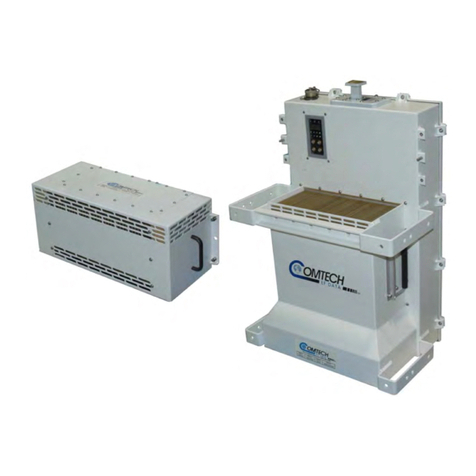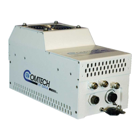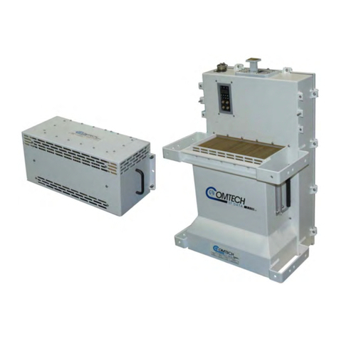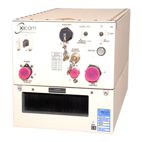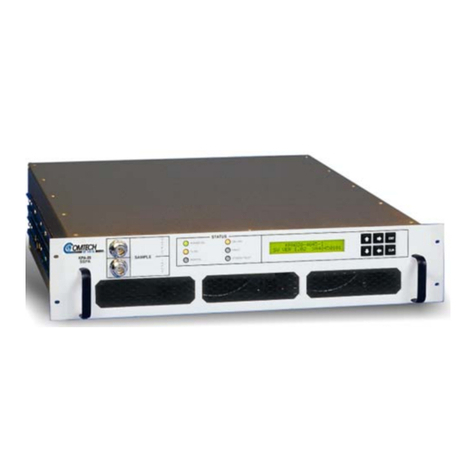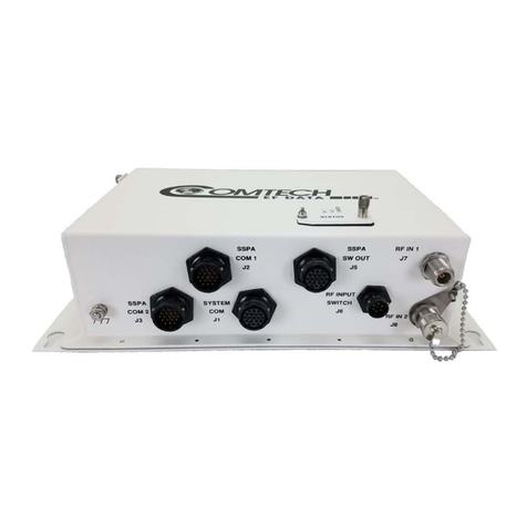
LPOD-R Outdoor Amplifier / Block Up Converter (BUC) MN-LPODR / CD-LPODR
Table of Contents Revision 3
v
2.3.4.3 ‘J3 | POWER IN’ – PS 1.5 Optional DC Power Main................... 2–7
2.3.5 ‘J6 | COM1’ Ethernet Communications Port........................................ 2–8
2.3.5.1 Fabricating a Weatherproof Ethernet Cable ............................. 2–9
2.3.6 ‘J6 | COM1’ Remote Communications and Discrete Control Port
(OPTIONAL).................................................................................................... 2–11
2.3.6.1 About Circular Connectors ...................................................... 2–12
2.3.7 Ground Connector ............................................................................. 2–13
2.4 LPOD-R Standalone (Single-Thread) Installations ............................. 2–14
2.4.1 Installation Manpower Recommendation ......................................... 2–14
2.4.2 Typical Required Installation Tools..................................................... 2–14
2.4.3 Pole Mount Installations (PS 1, PS 1.5) .............................................. 2–15
2.4.3.1 PL/12319 Universal Pole Mounting Kit ................................... 2–16
2.4.3.2 KT-0000095 Single Unit Mounting Kit (PS 1, PS 1.5) ............... 2–19
2.4.4 Spar Mount Installation (PS 1, PS 1.5) ............................................... 2–20
2.4.5 KT-0020987 OMT-Mount Installation (PS .5)..................................... 2–22
2.5 LPOD-R Startup ............................................................................... 2–23
2.5.1 Set the LPOD-R Power ON.................................................................. 2–23
2.5.2 Monitoring LPOD-R Operation with the LED Indicator (PS .5 ONLY) . 2–23
2.5.3 Recovering the User Interface Access................................................ 2–24
2.5.3.1 Recovery Steps Using a Windows PC ...................................... 2–24
CHAPTER 3. FIRMWARE UPDATE....................................................3–1
3.1 Firmware Overview........................................................................... 3–1
3.1.1 LPOD-R Firmware Update Procedure Summary .................................. 3–1
3.1.2 About Firmware Numbers, File Versions, and Formats ....................... 3–2
3.2 Prepare for the Firmware Download.................................................. 3–3
3.2.1 Required User-supplied Items ............................................................. 3–3
3.2.1.1 LPOD-R Connections for All Current Production Units ............. 3–3
3.2.1.2 LPOD-R Connections for Earlier PS 1 or PS 1.5 Units ................ 3–4
3.2.2 Configure the Terminal Emulator Program.......................................... 3–5
3.2.3 Get the LPOD-R Management IP Address and Firmware Information 3–5
3.2.3.1 Use the HTTP Interface to Find the Firmware Information....... 3–6
3.2.3.2 Use the Optional Serial Interface to Find the Firmware
Information.................................................................................................. 3–7
3.2.4 Make a Temporary Folder (Subdirectory) on the User PC ................... 3–7
