CRS-170A L-Band 1:1 Redundancy Switch MN/CRS170A.IOM / CD-CRS170A
Table of Contents Revision 14
viii
A.2.5 Modem-to-Switch (CRS-170A and CRS-150), Data / Control ‘Y’ Cable
(DB-25MDB-25M, DB-9M) ............................................................................................................A-7
A.2.6 Modem-to-Switch (CRS-170A and SMS-301), Control Cable (DB-9MDB-15M) ........A-8
A.3 IF / Data Interface Cables.........................................................................................................A-9
A.3.1 Switch-to-Modem / Modem-to-User, L-Band Coaxial Cable, RoHS, Type ‘N’ 50Ω......A-11
A.3.2 Switch-to-Modem / Modem-to-User, 70/140 MHz Coaxial Cable, RoHS, Type ‘BNC’ 75Ω.
...........................................................................................................................................A-12
A.3.3 Modem-to-User, Splitter Cable (DB-25F(2X) DB-25M) .............................................A-13
A.3.4 Modem-to-User, CDM-625A, CDM-625 Data ‘Y’ Splitter Cable (DB-9F(2X) DB-9M)....
...........................................................................................................................................A-14
A.3.5 Modem-to-User, Quad E1 ‘Y’ Splitter Adapter Cable (DB-9M(2X) DB-15F)............A-15
A.3.6 Modem-to-User, Quad E1 ‘Y’ Splitter Adapter Cable (DB-9M (2X) RJ-48F) ............A-16
A.3.7 Modem-to-User, Quad E1 ‘Y’ Splitter Adapter Cable Kit (KT-0000122).......................A-17
A.3.8 Modem-to-User, Overhead User Data ‘Y’ Splitter Cable (HD-44F(2X) HD-44M).....A-18
A.3.9 Modem-to-Modem CDM-625A, CDM-625 CnC®Plus Shielded Multi-drop Cable
(DB-9MDB-9M).............................................................................................................................A-19
A.3.10 Modem-to-User, RoHS Optical Gigabit Ethernet Cable Assemblies, Single-Mode OR Multi-
Mode ((2X) Type ‘LC’(4X) Type ‘LC’) ........................................................................................A-20
A.3.11 Modem-to-User, G.703 Balanced User Data ‘Y’ Splitter Cable (DB-15M(2X) DB-15M)..
...........................................................................................................................................A-21
A.3.12 Modem-to-User, HSSI User Data ‘Y’ Splitter Cable (HD-50M(2X) HD-50F)............A-22
A.3.13 Modem-to-User, RoHS OC-3 Cable Assemblies, Single-Mode OR Multi-Mode (Type
‘SC/UPC’(2X) Type ‘SC/UPC’) ...................................................................................................A-23
TABLES
Table 1-1. CRS-170A Compatibility Summary........................................................................................1–2
Table 3-1. Modem Side Type ‘Type ‘N’ Connectors...............................................................................3–4
Table 3-2. J3 | Control A Modem Connector Pinouts...............................................................................3–5
Table 3-3. J4 | Control B Modem Connector Pinouts...............................................................................3–5
Table 3-4. J7 | Rx and J8 | Tx ‘Type ‘N’ Connectors ...............................................................................3–6
Table 4-1. CRS-170A “Mode” DIP Switches – Product Compatibility Settings ...................................4–20
Table 4-2. CRS-170A “Switch Control” DIP Switches – Functional Settings.......................................4–20
FIGURES
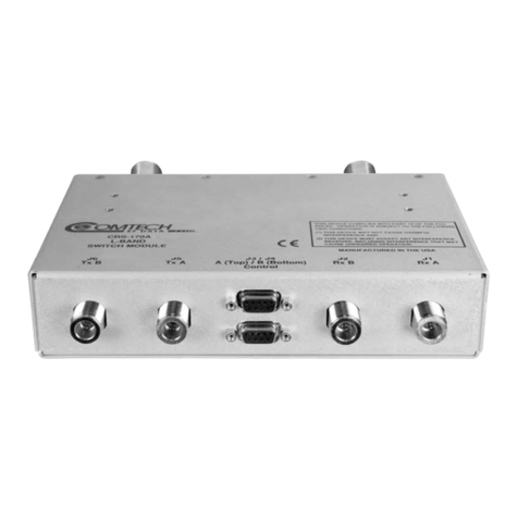
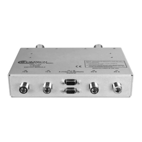
Figure 1-1. CRS-170A L-Band 1:1 Redundancy Switch Module ............................................................1–1
Figure 1-2. CRS-170A – Modem Side Connectors ..................................................................................1–3
Figure 1-3. CRS-170A – Top and Antenna Side Features........................................................................1–4
Figure 1-4. 1:1 IP Redundancy Managed Switch Mode for CDM-625A or CDM-625, Heights Remote
Gateway, Advanced VSAT CDM-850 or CDM-840, CDM-760, CDM-750, CDM-710GL, CDM-
710, or CDM-700.............................................................................................................................1–8
Figure 1-5. 1:1 IP Redundancy Managed Switch Mode – Switchover for CDM-625A or CDM-625,
Heights Remote Gateway, Advanced VSAT CDM-850 or CDM-840, CDM-760, CDM-750,
CDM-710GL, CDM-710, or CDM-700...........................................................................................1–9
Figure 1-6. CDM-625A or CDM-625 1:1 IP Redundancy Router Mode – ‘A’ Online..........................1–10
