1.4 M-216 Controls, Connectors and Indicators
Section 1 General Information (Continued)
Page 5
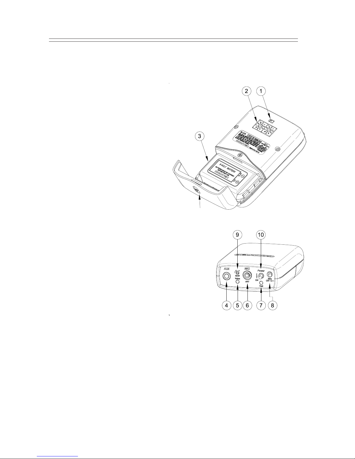
nCOMPAND AUTO/ OFF SWITCH:This switch overrides
the automatic selection of the companded channels to
non-companded operation (normally set to the right).
oCHANNELSWITCHES: These rotary switches
are set to the same channel as the receiver.
Actual frequency of operation must agree with
thereceiver.
(See page 14 for frequency selection chart.)
pBATTERYCOMPARTMENT: The
battery compartment features a hinged
battery cover and an alignment system that
ensures proper battery polarity. Battery
installation and removal is facilitated by simply
manipulating the bottom of the battery.
qAUXILIARYAUDIO INPUT JACK:
Allows transmitter to use line level, earphone
level, or fixed AUX as an audio source; also,
charging of rechargeable battery with NBC 9-2C charger.
rAUDIO“VOICE”MODULATIONINDICATOR:
This indicator is used in making adjustment with the
Audio Input Gain Control.
sMIC / ANTENNA JACK: This jack accepts an
electret type microphone having a 36” long cord with
a micro-mini 2.5mm mono plug. This jack is also used
for the screw-in specialty antenna when the auxiliary
audio input is used.
tPOWER/ BATTERY TEST INDICATOR: This LED indicator will illuminate
continuously when the unit is on indicating normal operation. When the battery voltage
drops below 6 volts, the LED will flash rapidly, indicating that a new battery or charging
is needed.
uOPTIONALMICMUTESWITCH: Thisswitchturnsoffthevoicefromthemicrophone
withoutturningoffthe transmitter carrier allowing the auxiliary input programtoremainon.
vAUDIOINPUT GAIN CONTROL: This is a microphone and AUX level input gain
control. This control is used with the “Voice” modulation indicator.
wON / OFF SWITCH: This switch turns the transmitter on and off.
Battery Cover
Latch