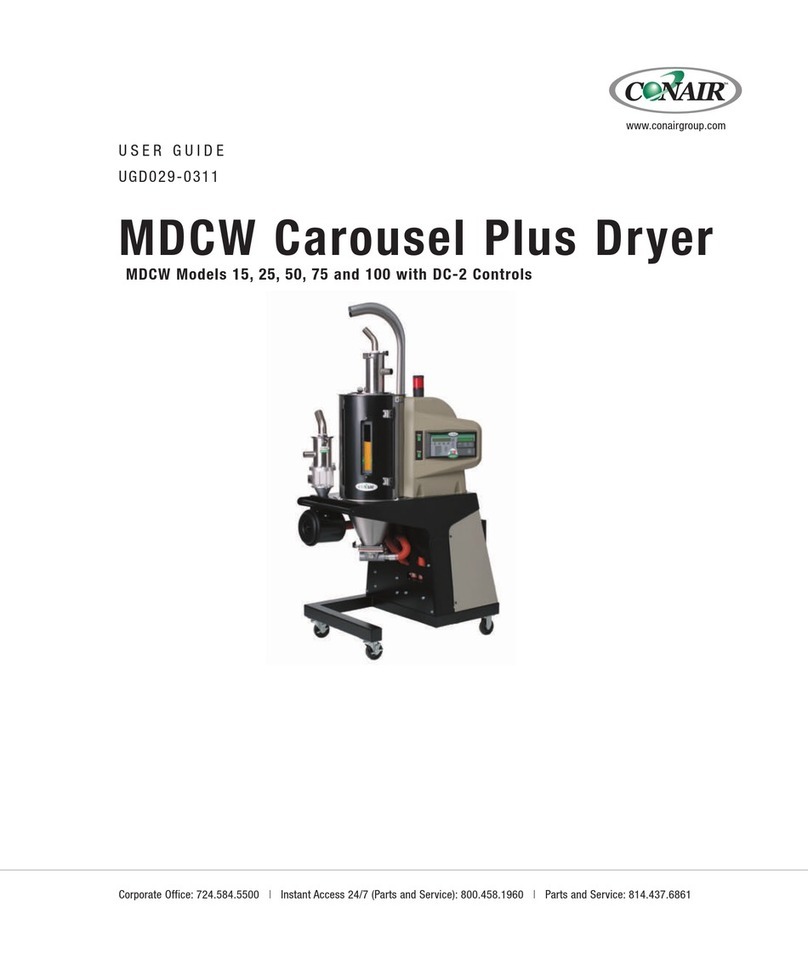
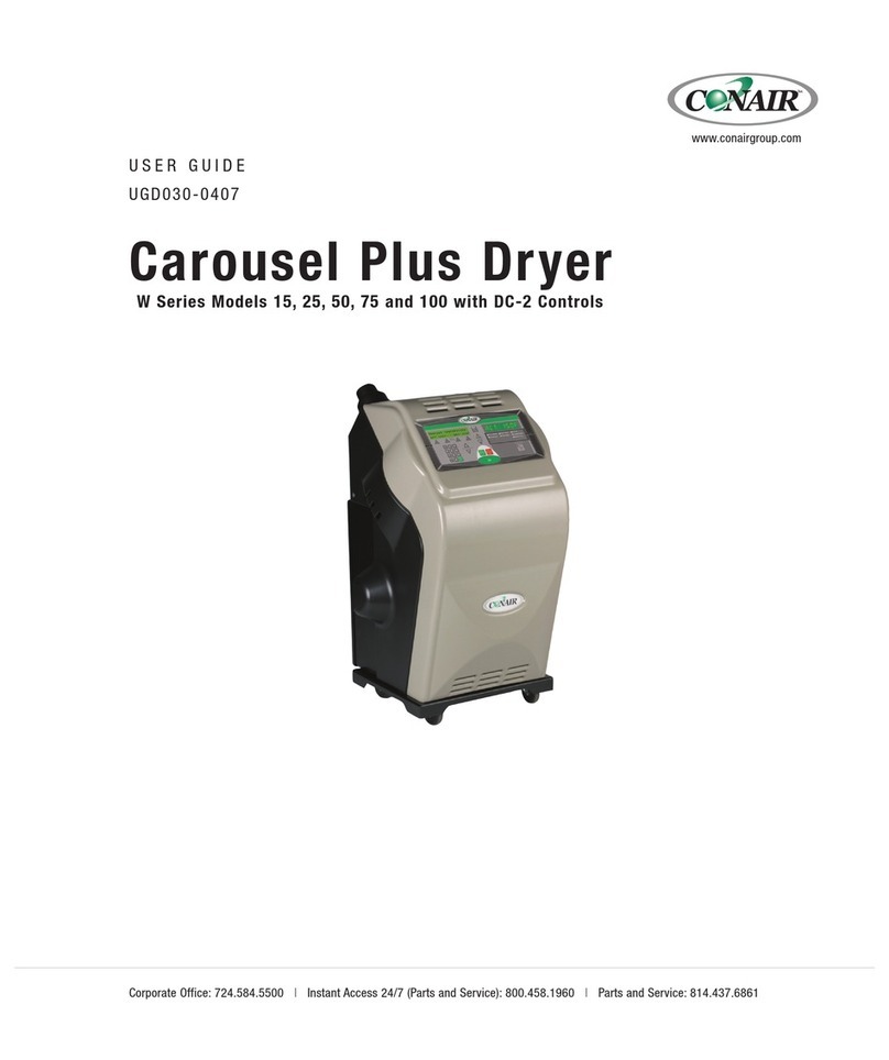
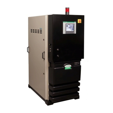
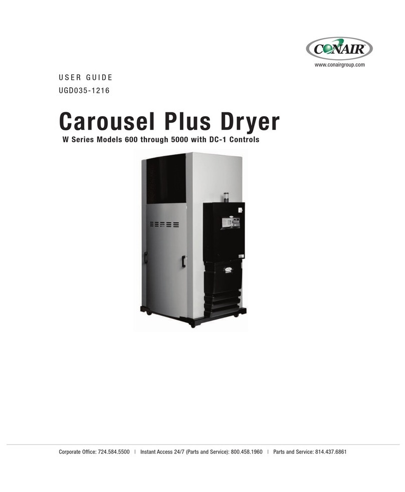
Conair Carousel Plus UGD043-1216 User manual

Carousel Plus Dryer
W Series Models 600 through 5000 with TouchViewTM Technology (Siemens)
Corporate Office: 724.584.5500 lInstant Access 24/7 (Parts and Service): 800.458.1960 l Parts and Service: 814.437.6861
USER GUIDE
UGD043-
www.conairgroup.com

Conair recommends recording the model and serial number(s) of your equipment
and the date you received it in the User Guide. Our service department uses this
information, along with the manual number, to provide help for the specific equip-
ment you installed.
Please keep this User Guide and all manuals, engineering prints and parts lists
together for documentation of your equipment.
Date:
Manual Number: UGD0043-126
Serial Number(s):
Model Number(s):
Software Version(s):
Multi Panel Operator Interface Terminal
Firmware Version Number:
Application File Name:
Programmable Logic Controller:
Firmware Version Number:
Application File Name:
Please record your equipment’s
model and serial number(s) and
the date you received it in the
spaces provided.
DISCLAIMER: Conair shall not be liable for errors contained in this User Guide or for incidental,
consequential damages in connection with the furnishing, performance or use of this information.
Conair makes no warranty of any kind with regard to this information, including, but not limited
to the implied warranties of merchantability and fitness for a particular purpose.
Copyright 201l Conair l All rights reserved
NOTE: The software,
firmware and application
file information for your
specific Dryer System is
contained on a serial tag
that was attached to the
inside of the Dryer’s con-
trol panel during assem-
bly.
✐

Table of Contents
1-1 Introduction
Purpose of the user guide . . . . . . . . . . . . . . . . . . . . . . . . . . . . . . . 1-2
How the guide is organized . . . . . . . . . . . . . . . . . . . . . . . . . . . . . . 1-2
Using the Carousel Plus Dryer with your system . . . . . . . . . . . . . . . 1-3
Your responsibilities as a user . . . . . . . . . . . . . . . . . . . . . . . . . . . . 1-3
ATTENTION: Read this so no one gets hurt . . . . . . . . . . . . . . . . . . . 1-4
How to use the lockout device . . . . . . . . . . . . . . . . . . . . . . . . . . . . 1-6
2-1 Description
What is the Carousel Plus Dryer System? . . . . . . . . . . . . . . . . . . . .2-2
Typical applications . . . . . . . . . . . . . . . . . . . . . . . . . . . . . . . . . . . . .2-2
How the Carousel Plus Dryer System works . . . . . . . . . . . . . . . . . .2-4
Specifications: Carousel Plus W Series
Dehumidifying Dryers . . . . . . . . . . . . . . . . . . . . . . . . . . . . . . 2-7
Dryer control options . . . . . . . . . . . . . . . . . . . . . . . . . . . . . . . . . . 2-10
3-1 Installation
Unpacking the boxes . . . . . . . . . . . . . . . . . . . . . . . . . . . . . . . . . . . 3-2
Preparing for installation . . . . . . . . . . . . . . . . . . . . . . . . . . . . . . . . 3-3
Positioning the dryer on the floor . . . . . . . . . . . . . . . . . . . . . . . . . . 3-4
Removing the cable tie from the dessicant wheel . . . . . . . . . . . . . 3-4
Installing the regeneration exhaust cover . . . . . . . . . . . . . . . . . . . . 3-4
Connecting the delivery air RTD probe . . . . . . . . . . . . . . . . . . . . . . 3-5
Connecting the process protection RTD . . . . . . . . . . . . . . . . . . . . . 3-5
Installing the return air inlet and air outlet adapters . . . . . . . . . . . . 3-6
Connecting the main power . . . . . . . . . . . . . . . . . . . . . . . . . . . . . . 3-7
Table of Contents l i

Opening the dryer doors . . . . . . . . . . . . . . . . . . . . . . . . . . . . . . . . 3-8
Connecting the air hoses to a single hopper . . . . . . . . . . . . . . . . . . 3-9
Connecting the air hoses to ResinWorks . . . . . . . . . . . . . . . . . . . 3-10
Connecting the dryer to the hopper . . . . . . . . . . . . . . . . . . . . . . . 3-11
Connecting the dryer to ResinWorks . . . . . . . . . . . . . . . . . . . . . . 3-11
Mounting a loader on the hopper . . . . . . . . . . . . . . . . . . . . . . . . . 3-11
Connecting the air hose adapters . . . . . . . . . . . . . . . . . . . . . . . . . 3-12
Connecting the aftercooler/intercooler and
optional precooler . . . . . . . . . . . . . . . . . . . . . . . . . . . . . . . 3-13
Checking for proper air flow . . . . . . . . . . . . . . . . . . . . . . . . . . . . . 3-15
Testing the primary receiver . . . . . . . . . . . . . . . . . . . . . . . . . . . . . 3-18
Testing the secondary receiver . . . . . . . . . . . . . . . . . . . . . . . . . . . 3-20
Testing the installation . . . . . . . . . . . . . . . . . . . . . . . . . . . . . . . . . 3-22
4-1 Operation
The Carousel Plus Dryer control panel. . . . . . . . . . . . . . . . . . . . . . . 4-2
How to navigate the control screens . . . . . . . . . . . . . . . . . . . . . . . . 4-3
Control function flow charts . . . . . . . . . . . . . . . . . . . . . . . . . . . . . . 4-6
Login flow chart . . . . . . . . . . . . . . . . . . . . . . . . . . . . . . . . . . 4-6
Basic controls . . . . . . . . . . . . . . . . . . . . . . . . . . . . . . . . . . . 4-7
Operation flow chart 1 . . . . . . . . . . . . . . . . . . . . . . . . . . . . . 4-8
Operation flow chart 2 . . . . . . . . . . . . . . . . . . . . . . . . . . . . . 4-9
Dew point package controls . . . . . . . . . . . . . . . . . . . . . . 4-11
Operation flow chart 1 . . . . . . . . . . . . . . . . . . . . . . . . . . . . 4-12
Operation flow chart 2 . . . . . . . . . . . . . . . . . . . . . . . . . . . . 4-13
Drying monitor package controls . . . . . . . . . . . . . . . . . . 4-15
Operation flow chart 1 . . . . . . . . . . . . . . . . . . . . . . . . . . . . 4-16
Operation flow chart 2 . . . . . . . . . . . . . . . . . . . . . . . . . . . . 4-17
Operation flow chart 3 . . . . . . . . . . . . . . . . . . . . . . . . . . . . 4-18
ii l Table of Contents
Example set point change . . . . . . . . . . . . . . . . . . . . . . . . . 4-19
Control function descriptions . . . . . . . . . . . . . . . . . . . . . . . . . . 4-25
Carousel Plus Dryer System security levels . . . . . . . . . . . . . . . . . 4-44
Starting the Carousel Plus Dryer System . . . . . . . . . . . . . . . . . . . 4-45
Adjusting the temperature set point . . . . . . . . . . . . . . . . . . . . . . . 4-47
Using the auto start timer . . . . . . . . . . . . . . . . . . . . . . . . . . . . . . 4-48
Stopping the Carousel Plus Dryer System . . . . . . . . . . . . . . . . . . 4-50
Control function descriptions . . . . . . . . . . . . . . . . . . . . . . . . . . 4-52
Carousel Plus Dryer System security levels . . . . . . . . . . . . . . . . . 4-56
5-1 Maintenance
Preventative maintenance checklist . . . . . . . . . . . . . . . . . . . . . . . . 5-2
Checking the dewpoint . . . . . . . . . . . . . . . . . . . . . . . . . . . . . . . . . 5-4
Cleaning the hopper . . . . . . . . . . . . . . . . . . . . . . . . . . . . . . . . . . . . 5-5
Cleaning the process filter . . . . . . . . . . . . . . . . . . . . . . . . . . . . . . . 5-6
Cleaning the regeneration filter . . . . . . . . . . . . . . . . . . . . . . . . . . . 5-8
Cleaning the aftercooler coils . . . . . . . . . . . . . . . . . . . . . . . . . . . . . 5-9
Draining the volatile drain . . . . . . . . . . . . . . . . . . . . . . . . . . . . . . 5-10
Inspecting the hoses and gaskets . . . . . . . . . . . . . . . . . . . . . . . . 5-11
Cleaning the precooler coils . . . . . . . . . . . . . . . . . . . . . . . . . . . . . 5-12
Cleaning the volatile trap on the demister . . . . . . . . . . . . . . . . . . . 5-13
6-1 Troubleshooting
Before beginning. . . . . . . . . . . . . . . . . . . . . . . . . . . . . . . . . . . . . . . 6-2
A few words of caution . . . . . . . . . . . . . . . . . . . . . . . . . . . . . . . . . 6-3
DIAGNOSTICS
How to identify the cause of a problem . . . . . . . . . . . . . . . . . . . . . 6-4
Shutdown alarms . . . . . . . . . . . . . . . . . . . . . . . . . . . . . . . . . . . . . 6-7
Table of Contents l iii

Passive alarms . . . . . . . . . . . . . . . . . . . . . . . . . . . . . . . . . . . . . . 6-14
Dew point troubleshooting . . . . . . . . . . . . . . . . . . . . . . . . . . . . . . 6-22
Poor material drying troubleshooting. . . . . . . . . . . . . . . . . . . . . . . 6-23
REPAIR
Replacing fuses. . . . . . . . . . . . . . . . . . . . . . . . . . . . . . . . . . . . . . . 6-28
Checking heater solid state relays. . . . . . . . . . . . . . . . . . . . . . . . . 6-29
Checking or replacing temperature sensors . . . . . . . . . . . . . . . . . 6-30
Replacing the regeneration heater . . . . . . . . . . . . . . . . . . . . . . . . 6-31
Replacing the desiccant wheel assembly . . . . . . . . . . . . . . . . . . . 6-37
Replacing the desiccant wheel motor . . . . . . . . . . . . . . . . . . . . . . 6-43
A Appendix
We’re here to help . . . . . . . . . . . . . . . . . . . . . . . . . . . . . . . . . . . . . A-1
How to contact customer service . . . . . . . . . . . . . . . . . . . . . . . . . . A-1
Before you call... . . . . . . . . . . . . . . . . . . . . . . . . . . . . . . . . . . . . . . A-1
Equipment guarantee . . . . . . . . . . . . . . . . . . . . . . . . . . . . . . . . . . A-2
Performance warranty . . . . . . . . . . . . . . . . . . . . . . . . . . . . . . . . . . A-2
Warranty limitations . . . . . . . . . . . . . . . . . . . . . . . . . . . . . . . . . . . . A-2
iv l Table of Contents

Table of Contents l v

vi l Table of Contents

Introduction
Purpose of the user guide. . . . . . . . . . . . . . 1-2
How the guide is organized. . . . . . . . . . . . . 1-2
Using the Carousel Plus Dryer
with your system . . . . . . . . . . . . . . . . . 1-3
Your responsibilities as a user. . . . . . . . . . . 1-3
ATTENTION:
Read this so no one gets hurt . . . . . . . . 1-4
How to use the lockout device. . . . . . . . . . . 1-6
SECTION
1
Introduction l 1-1
1
Introduction

✐
Purpose of the User Guide
This User Guide describes the Conair Carousel Plus Dryer with
TouchViewTM Technology (Siemens) and explains step-by-step how to
install, operate, maintain and repair this equipment.
Before installing this product, please take a few moments to read the User
Guide and review the diagrams and safety information in the instruction
packet. You also should review manuals covering associated equipment in
your system. This review won’t take long, and it could save you valuable
installation and operating time later.
How the Guide is Organized
Symbols have been used to help organize the User Guide and call your
attention to important information regarding safe installation and operation.
Symbols within triangles warn of conditions that could be hazardous to users or
could damage equipment. Read and take precautions before proceeding.
Numbers indicate tasks or steps to be performed by the user.
A diamond indicates the equipment’s response to an action performed by the user.
An open box marks items in a checklist.
A circle marks items in a list.
Indicates a tip. A tip is used to provide you with a suggestion that will help you with
the maintenance and the operation of this equipment.
Indicates a note. A note is used to provide additional information about the steps
you are following throughout the manual.
1
◆
❒
•
✒
1-2 l Introduction

Introduction l 1-3
Using the Carousel Plus Dryer with
Your System
The Conair Carousel Plus Dryer with TouchViewTM Technology used within your
system is factory configured to be used as a central dryer, as a stand alone dryer
with process heat from a Heater Pack (controlled by the dryer), or in conjunc-
tion with Resin Works or dedicated hopper using HTC or GasTrac. Therefore,
this manual incorporates the information necessary to use these dryers for cen-
tral drying applications as well as stand alone drying applications.
Your Responsibility as a User
You must be familiar with all safety procedures concerning installation, opera-
tion and maintenance of this equipment. Responsible safety procedures include:
•Thorough review of this User Guide, paying particular attention
to hazard warnings, appendices and related diagrams.
•Thorough review of the equipment itself, with careful attention
to voltage sources, intended use and warning labels.
•Thorough review of instruction manuals for associated equipment.
•Step-by-step adherence to instructions outlined in this User Guide.
1
Introduction

1-4 l Introduction
ATTENTION:
Read this so no one gets hurt
We design equipment with the user’s safety in mind. You can avoid the potential
hazards identified within this system by following the procedures outlined below
and elsewhere in the User Guide.
WARNING: Improper installation, operation or
servicing may result in equipment damage or
personal injury.
This equipment should be installed, adjusted and serviced by qualified
technicians who are familiar with the construction, operation and
potential hazards of this type of machinery.
All wiring, disconnects and fuses should be installed by qualified elec-
trical technicians in accordance with electrical codes in your region.
Always maintain a safe ground. Do not operate the equipment at power
levels other than what is specified on the machine serial tag and data
plate.
WARNING: Voltage hazard
This equipment is powered by three-phase alternating current,
as specified on the equipment’s serial tags and data plates. Reference
supplemental equipment’s manuals for their power requirements.
A properly-sized conductive ground wire from the incoming power
supply must be connected to the chassis ground terminal inside the
electrical enclosure. Improper grounding can result in severe personal
injury and erratic machine operation.
Always disconnect and lock out the incoming main power source before
opening the electrical enclosure or performing non-standard operating
procedures, such as routine maintenance. Only qualified personnel
should perform troubleshooting procedures that require access to the
electrical enclosure while power is on.
(continued)

1
Introduction
Introduction l 1-5
ATTENTION:
Read this so no one gets hurt (continued)
We design equipment with the user’s safety in mind. You can avoid the potential
hazards identified within this system by following the procedures outlined below
and elsewhere in the User Guide.
CAUTION: Hot Surfaces.
Always protect yourself from hot surfaces inside the dryer and hopper.
Also exercise caution around exterior surfaces that may become hot
during use. These include the hopper door frame, the exterior of an
uninsulated hopper, the return air hose and the dryer’s process filter
housing and exhaust outlet and the Hopper Temperature Controller
(HTC) or GasTrac Heater (CGT).
WARNING: Do not place aerosol, compressed
gas or flammable materials on or near this
equipment.
The hot temperatures associated with the drying process may cause
aerosols or other flammable materials placed on the dryer or hopper to
explode.

1-6 l Introduction
How to Use the Lockout Device
CAUTION: Before performing maintenance or repairs on this product, you should
disconnect and lockout electrical power sources to prevent injury from unexpected
energization or start-up. A lockable device has been provided to isolate this
product from potentially hazardous electricity.
Lockout is the preferred method of isolating machines or equipment from energy
sources. Your Conair product is equipped with the lockout device pictured below.
To use the lockout device:
1Stop or turn off the equipment.
2Isolate the equipment from the electric power. Turn the rotary
disconnect switch to the OFF, or “O” position.
3Secure the device with an assigned lock or tag. Insert a lock or tag
in the holes to prevent movement.
4The equipment is now locked out.
WARNING: Before removing lockout devices and returning switches to the ON
position, make sure that all personnel are clear of the machine, tools have been
removed and all safety guards reinstalled.
To restore power, turn the rotary disconnect back to the ON position:
1Remove the lock or tag.
2Turn the rotary disconnect switch to the ON or “I” position.
OFF
O
ON
I
OFF
O
ON
I
OFF
O
ON
I

Description l 2-1
Description
What is the Carousel Plus Dryer? . . . . . . . . . 2-2
Typical applications. . . . . . . . . . . . . . . . . . 2-2
How it works . . . . . . . . . . . . . . . . . . . . . . 2-4
Specifications: Carousel Plus
W Series Dehumidifying Dryers . . . . . . . 2-7
Carousel Plus Dryer control options . . . . . . 2-10
SECTION
2
2
Description

2-2 l Description
What is the Carousel Plus W Series
Dryer?
The Carousel Plus W Series Dryer with TouchViewTM produces low-dew point air
that removes moisture from hygroscopic plastics. The dryer pulls moist air from a
drying hopper and circulates it through a dehumidifying desiccant wheel. The
dryer then circulates the air through the material in the hopper.
The dryer’s closed-loop design ensures a continuous supply of dehumidified air
while preventing contamination from moisture in the plant.
Typical Applications
1Dryer on the floor, single hopper (with a Heater Pack) on a floor stand.
The Carousel Plus W Series Dryer can be used successfully in applications that
require:
•A contamination-free drying environment.
•A constant flow of dehumidified air.
NOTE: The W600 - 5000 pro-
vides no heat to the process
air. A separate heat source is
required at the hopper(s) inlet
to heat the air to the desired
drying temperature.
✐
(continued)

Description l 2-3
2
Description
Typical Applications (continued)
Model Drying Temperature Range
Low temperature (with precooler)* 100° - 150°F {38° - 66°C}
High heat (with aftercooler)* 150° - 375°F {66° - 191°C}
Low-high (aftercooler & precooler)* 100° - 375°F {38° - 191°C}
* See Installation section entitled, Connecting the Aftercooler and Optional
Precooler and Appendix B.
•Throughput rates of 600 to 5000 lbs {271 to 2267 kg} per hour (some
materials can be run at a higher rate).
•Dew points of -40°F {-40°C}.
Use the aftercooler when:
•Throughput rates are less than 50% of the dryer’s rated capacity.
•You a re p re -d ry i ng m at er ia l at t em p er at ur es ove r 15 0° F {6 6° C }
•The return air is 120°F {49°C} or above.
NOTE: Temperature setback is only available in conjunction with the Hopper Temperature
Controller (HTC).
✐
NOTE: Carousel Plus W Series 600-1000 Dryers use an aftercooler located before the process
blower. Carousel Plus W Series 1600-5000 uses an aftercooler located after the process blower.
✐
NOTE: The aftercooler reduces the temperature of air returning from the drying hopper, improving
the efficiency of the desiccant.
✐

How It Works
The Process (Drying) Cycle (W1600 - 5000)
Process air from the hopper is pulled into the dryer, through the process filter and
then into the process blower inlet. Air exits the process blower and then enters the
intercooler, then passes through the desiccant wheel, where moisture is removed.
The air exits the dryer and passes through the precooler (if installed), then into the
process heat source. After the air exits the process heat source it then goes into the
hopper inlet through internal piping, then to the spreader cone, which evenly dis-
tributes the air through the material.
The Cooling Cycle (All models except W2400, W4000 and W5000)
Regenerated desiccant must be cooled before it rotates back into the process cycle.
The process blower pushes the process air through the desiccant wheel. A small
amount of the process air is diverted through a small section of the desiccant wheel
to cool the air. The cooling air then returns back to the process air stream at the
start of the process cycle.
The Regeneration Cycle
The regeneration blower pulls air through the regeneration filter into the dryer’s
regeneration heater. The air is heated to 350°F {177°C} before it is pushed into the
“wet” section of the desiccant wheel. The hot air purges moisture from the
desiccant. The moist air is blown out the moisture exhaust at the top of the dryer.
The Process (Drying) Cycle (W600 - 1000)
Process air from the hopper is pulled into the dryer, through the process filter and
then into the process blower inlet. Air exits the process blower and then enters the
aftercooler, then passes through the desiccant wheel, where moisture is removed.
The air exits the dryer and passes through the precooler (if installed), then into the
process heat source. After the air exits the process heat source it then goes into the
hopper inlet, then to the spreader cone, which evenly distributes the air through the
material.
2-4 l Description
NOTE: Changing the regen-
eration cycle temperature
setpoint requires a
Maintenance level user
login.
Activating the optional dew-
point control will override
the temperature setting.
✐

2
Description
How It Works (continued)
(W600 - W1600, and W3200)
Description l 2-5
NOTE: Depending on your system configuration, and available options, the system flow may be slightly
different than this representation.
✐

How It Works (continued)
(W2400, W4000 and W5000)
.
2-6 l Description
Protected under
United States Patent
No. 7,101,414 and
other US and Foreign
Patents Pending.
.
NOTE: Carousel Plus W Series 600-1000 Dryers use an
aftercooler located before the process blower. Carousel
Plus W Series 1300-5000 dryers use an aftercooler located
after the process blower.
✐
Power Purge
W2400, 4000 and 5000 models have a Power Purge (cooling
fan) feature integral to the desiccant wheel assembly.
Table of contents
Other Conair Dryer manuals

Conair
Conair 200 User manual

Conair
Conair 1002XDIC User manual

Conair
Conair MDCW Carousel Plus W15 User manual

Conair
Conair 100 User manual

Conair
Conair HTC 30 User manual

Conair
Conair 174NC User manual

Conair
Conair Carousel Plus W Series User manual

Conair
Conair 289 User guide

Conair
Conair W600 User manual

Conair
Conair W Series User manual
Popular Dryer manuals by other brands

Zanussi
Zanussi TC470 Instruction booklet

Whirlpool
Whirlpool DUET SPORT W10260035A Use and care guide

Siemens
Siemens WT45N203GB User manual and installation instructions

GE
GE DCB330 and Owner's manual and installation instructions

Whirlpool
Whirlpool LE6090XS Use & care guide

Whirlpool
Whirlpool WED9600TA1 Tech sheet