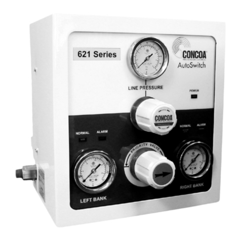
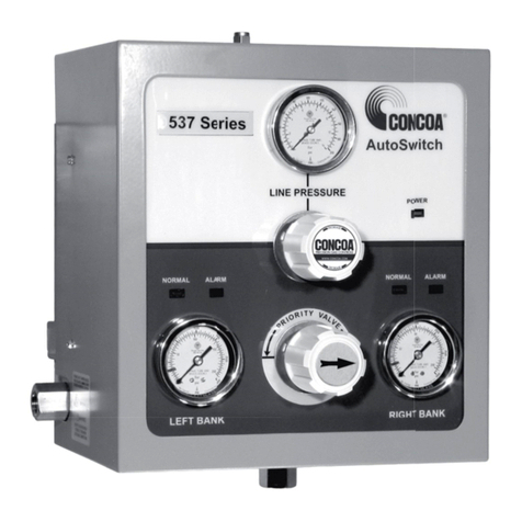
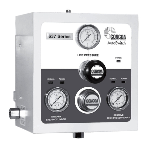
Concoa INTELLISWITCH User manual

ADI 9502-A
4,500 PSI
INTELLISWITCHTM
ELECTRONIC
SWITCHOVER
Controls Corporation of America
1501 Harpers Road • Virginia Beach, VA 23454
To Order Call 1-800-225-0473 or 757-422-8330 • Fax 757-422-3125
www.concoa.com
INSTALLATION AND OPERATING INSTRUCTIONS
Carefully Read These Instructions Before Operating
October 2005
®
Certied ISO 9001:2000
PATENT PENDING

2
3
DESCRIPTION OF PRODUCT
The IntelliSwitch is a device used to monitor, control and switch the ow of gas from cryogenic or high
pressure cylinders from either of two independent sources to a single point of use.
It consists of two controllable valves that direct the ow of gas into a delivery regulator.
Pressure coming into the IntelliSwitch is monitored and displayed on two independent 4-digit displays. The
outlet pressure of the system is monitored and displayed on a 3-digit display. Outlet pressure adjustment is
available using a knob on the front panel.
A series of indicator lights show the status of the system at any given time.
The status of the IntelliSwitch may be monitored remotely via a serial port. In addition, the IntelliSwitch can
interface with any of the CONCOA Remote Alarms.
There are two basic models of the IntelliSwitch. One uses the delivery gas to activate the valves used for bank
switching. The other uses compressed air or an inert gas to activate the valves used for bank switching.
Each model features several different versions targeted at the pressures and ows of specic applications.
FEATURES
Operation from Multiple Gas Sources
The IntelliSwitch is capable of operating from 230, 350, and 500 PSI liquid cylinders, 4,500 PSI high
pressure cylinders, or any combination.
Look Back
The IntelliSwitch switches from one bank to the other based upon the pressure supplied to the selected bank.
When the volume of the liquid in the cylinder becomes low or the gas ow becomes particularly high, it is not
uncommon for the pressure to drop below the switching point even if there is plenty of gas left in the cylinder.
When a typical switchover enters such a state, two undesirable situations may occur. First, the system may
switch to the reserve temporarily until pressure builds on the primary enough to cause the system to switch
back. This situation often leads to depleting both sides at the same time as the system rapidly alternates
drawing from both sides or even draws both sides at the same time. Second, the system may permanently
switch to the reserve leaving unused product in the primary and triggering a false alarm.
To avoid either of these situations, the IntelliSwitch has a Look Back feature that allows the system to switch
banks and wait a predetermined time period before checking the former primary cylinder. If the pressure has
recovered enough, the system will switch back to the former primary cylinder. This look back time allows the
pressure building circuit to recover and build sufcient pressure to supply the system and fully draw down the
primary cylinder before an alarm is triggered indicating the cylinder is empty, allowing maximum utilization
of cylinder contents.
Switchback Delay
Using the Look Back feature alone can result in the switchover switching back several times well after the
cylinder can provide a useful gas supply. To prevent this, the Switchback Delay feature keeps track of how
often the IntelliSwitch switches back to a liquid cylinder that has been used and whose pressure has been
restored to be used again.
If the system switches away from the priority side before the Switchback Delay timer has timed out, the
system determines that all the useful gas has been extracted from the cylinder and switches to the auxiliary
side and draws from it.

2
3
Hysteresis
This feature is a pressure value added to the switchover pressure value to determine the pressure at which the
IntelliSwitch will switch back to a cylinder after the “Look Back” time has expired. This features provides
added protection against inadvertently drawing from the reserve bank when the primary still has gas.
Economizer Function
When using liquid cylinders in switchover application, it is common for the reserve cylinder to build pressure
due to the vaporization of liquid within the cylinder. When this pressure reaches the set point of the relief
valve on the liquid cylinder, the relief valve will open, venting gas to the atmosphere. The IntelliSwitch
constantly monitors the reserve cylinder and, at a predetermined pressure, will change the valving to allow gas
from the headspace of the reserve cylinder to feed the system, thus drawing down the pressure in the reserve
cylinder. There are three pressure ratings for liquid cylinder relief valves, 230 PSIG, 350 PSIG and 500 PSIG;
the IntelliSwitch has predetermined settings for all three types that may be selected on the front panel of the
system.
Settable Switchover Pressure
The IntelliSwitch can be congured to switch at pressures ranging from 100 to 500 PSI. This value is factory
set but can be changed in the eld. To change this value refer to the section on changing the switchover
pressure.
Manual Bank Switching
It is possible to manually change the side that gas is being drawn from by pressing the “BANK SELECT”
button provided that there is sufcient pressure on the side being switched to.
Selectable Units of Measure
The default units of measure for the IntelliSwitch are PSI. Alternate units of BAR or MPA can be selected by
changing internal DIP switch settings. To change units of measure refer to the section on changing units of
measure.
Security Lockout
The IntelliSwitch has the ability to electronically lockout the front panel buttons to discourage tampering.
The factory default setting is OFF or disabled. Refer to section on Keypad Security Lockout for details.
Alarm Notication
The IntelliSwitch is designed to interface with CONCOA Remote Alarms and comes with the necessary
mating connector for their use. Refer to the section on connecting a remote alarm for more information.
Serial Port
The IntelliSwitch is capable of communicating to peripheral equipment via a standard serial port. For more
information on the serial port refer to the section on connecting to a serial port.
Burst Disk Overpressure Protection
The IntelliSwitch is equipped with a replaceable burst disk for each bank to protect the system from extreme
pressure increases and liquid withdrawal.

4
5
USER RESPONSIBILITY
Service to this product should only be performed by CONCOA or an authorized CONCOA agent. Requests
for service may be made through CONCOA CUSTOMER SERVICE at 1-800-225-0473. Written
requests may be made using CONCOA’s FAX number at 1-757-422-3125 or CONCOA’s E-MAIL at
CONCOA accepts no responsibility for damage or injury if this product is modied in any way.
CONCOA assumes/accepts no liability or responsibility for damage to individuals or equipment that may
occur when using this product.
SAFETY
THIS PRODUCT IS NOT INTENDED FOR USE WITH TOXIC GASES, FLAMMABLE GASES OR
CORROSIVE GASES.
Basic safety precautions must be followed to reduce the risk of re, electrical shock or injury.
· Connect the IntelliSwitch to the correct line voltage. A label on the product identies what voltage it is
wired for. CONNECTION TO AN INCORRECT VOLTAGE CAN CAUSE SERIOUS DAMAGE
TO THE PRODUCT AND WILL VOID ANY WARRANTY.
· While the IntelliSwitch Switchover is dust and moisture resistant, it is NOT water-proof or completely
sealed. It should be installed where it will not be subjected to rain or high concentrations of dust. Never
pour or spray liquids directly onto the product.
· Install IntelliSwitch where the ambient temperature range is between 0° F and 140° F.
· Do not install this product in a hazardous environment.
· If product appears damaged in any way, do not use and request service from CONCOA.
· Do not attempt to operate the IntelliSwitch with the front panel off.
· Consult the cylinder distributor for the proper use of cylinders and for any restrictions on their use (such
as ow rate and temperature requirements).
· Store cylinders with valve caps screwed on, and chain cylinders to a supporting wall or column.
· Handle cylinders carefully and only with valve caps screwed on. The cap will reduce the chance that the
cylinder valve will break off if the cylinder is accidentally dropped or falls over. The cap also protects
the cylinder valve from damage to screw threads, which could cause leaky connections.
· All manifolds used with ammable gases should be provided with approved ashback arrestors to stop
any burning gas in the pipeline from getting back to the manifold or cylinders.
· No smoking should be permitted near oxygen, nitrous oxide, any other oxidizer, ammable gases, or
ammable mixtures, or in areas where cylinders are stored.
· Where an oxidizer (such as nitrous oxide or oxygen) is used, the manifold and cylinders must be kept
clean. No oil, grease, or combustible substances should come in contact with oxygen or nitrous oxide
storage or handling equipment. Such materials in contact with oxygen or nitrous oxide are readily
ignitable and, when ignited, will burn intensely.
· Never lift gas cylinders with a magnetic lifting device.
· Never use an open ame when leak testing.
· Always open valves slowly when high-pressure gases are being used.

4
5
· Always be sure that a cylinder contains the correct gas before connecting it to any manifold.
· Always leak-test any manifold or distribution pipeline before using.
· Always be sure that the gas in a pipeline is the correct gas for the intended use.
· Always close all cylinder valves before disconnecting cylinders from a manifold.
· Always remove all empty cylinders from a manifold before connecting full cylinders.
· Always test cylinders to be sure the cylinders are full before connecting to a manifold.
All gas distribution piping systems must meet the appropriate industrial standards for the intended service and
must be thoroughly cleaned before using. For the United States, some applicable safety rules and precautions
are listed below:
1. American National Standards Institute standard Z49.1, Safety in Welding and Cutting, American
Welding Society, 2501 NW Seventh Street, Miami, Florida 33125
2. N.F.P.A. Standard 51, Oxygen-Fuel Gas systems for Welding and Cutting, N.F.P.A., 470 Atlantic Avenue,
Boston, Massachusetts 02210
3. N.F.P.A. Standard 51B, Cutting and Welding Processes (same address as #2).
4. CONCOA publication ADE 872, Safety Precautions in Welding and Cutting.
5. Local Ordinances
6. O.S.H.A. Standard 29 CFR
7. C.G.A. Pamphlet C-4, American National Standard Method of Marking Portable Compressed Gas
Containers to Identify the Material Contained.
8. C.G.A. Pamphlet G-4, Oxygen – Information on the properties, manufacture, transportation, storage,
handling, and use of oxygen.
9. C.G.A. Pamphlet G-4.1, Equipment Cleaned for oxygen service.
10. C.G.A. Pamphlet G-4.4, Industrial Practices for Gaseous Oxygen Transmission and Distribution Piping
Systems.
11. C.G.A. Pamphlet G-5, Hydrogen – Information on the properties, manufacture, transportation, storage,
handling, and use of hydrogen.
12. C.G.A. Pamphlet G-6, Carbon Dioxide – Information on the properties, manufacture, transportation,
storage, handling, and use of carbon dioxide.
13. C.G.A. Pamphlet G-6.1, Standard for Low Pressure Carbon Dioxide Systems at Consumer Sites.
14. C.G.A. Pamphlet P-1, Safe Handling of Compressed Gases in Containers.
15. C.G.A. Safety Bulletin SB-2, Oxygen Decient Atmospheres.
C.G.A. Pamphlets can be obtained from the Compressed Gas Association, 1235 Jefferson Davis Highway,
Arlington, VA 22202-3239, (703) 979-0900. Publications: (703) 979-4341. Fax: (703) 979-0134.

6
7
CONNECTING THE INTELLISWITCH
The key to any successful system installation is understanding the application and sizing the components
properly.
The inlets and outlet on the IntelliSwitch are 1/2” Female NPT ttings. These ttings have an anti-rotation
plate around them to keep them from twisting during installation. However, it is strongly recommended that
two wrenches be used when tightening external devices to these ttings.
The IntelliSwitch uses four mounting tabs for mounting to a wall or panel. Refer to Figure 8 for the
dimensions of the system. Anchor the IntelliSwitch securely to a wall or panel at a height adequate to
conveniently connect a manifold or pigtail.
If using an external air-driven IntelliSwitch, connect the air source to the air inlet on the bottom of the
system.
Note: Air used for this system must not contain moisture or oil. Air pressure should be in the range of 65-85
PSIG and must not exceed 100 PSIG.
Figure 1 shows a typical installation.
Once all mechanical connections are made, connect the Remote Alarm, and serial device to the IntelliSwitch.
If using an external air-driven IntelliSwitch, turn the air source on at this time.
Finally connect AC power to the IntelliSwitch. The system is factory set to operate at either 115VAC 60hz or
230 VAC 60hz. Connection of the IntelliSwitch to the incorrect input voltage will damage the product and
void any warranty.
Pressurize both sides of the system; if using internal process gas-driven IntelliSwitch, pressurize the right side
rst. The inlet pressure readings will appear on the two 4-digit displays. If necessary use the Bank Select
pushbutton to choose the side considered to be the primary gas source. If gas pressures are on before the
system is powered up, the IntelliSwitch will default to the left side as the primary side.
Using the outlet pressure adjustment knob, set the desired delivery pressure. The value will appear on the 3-
digit display.
INUSE
REMOTE
READY REPLACE
RIGHT BANK
PWRBAR
PSI
LEFT BANK
REPLACE INUSE
DELIVERY
READY
34BAR
500PSI
MAX.
3000PSI
GAS
CRYOGENIC
24BAR
350PSI230PSI
16BAR
BANKSELECT
GASSOURCE
34BAR
500PSI
CRYOGENIC
24BAR
350PSI
GASSOURCE
RESET
GAS
MAX.
3000PSI
ADJUSTMENT
DELIVERY PRESSURE
®
IntelliSwitch
16BAR
230PSI
SYSTEM 2
SYSTEM 4
SYSTEM 3
SYSTEM 1
SERIALPORT
INPUT
LEFTBANK
OUTPUT
RIGHTBANK
TEST
SILENCE
ALARM
Multi-Station
Alarm
Figure 1

6
7
Normal operation of the IntelliSwitch can now begin. The “primary” or “active” side of the system, whether
left or right, will have the green Ready light ON and the In Use light ON. The “secondary” side or the “in-
active” side will have only the green Ready light ON.
Lighted green lights above the Source Select buttons should match the types of cylinders being used by each
side.
All switching is automatic. If the primary side drops below the set switchover point, the system will transfer
to the reserve side and the status lights will indicate the transition. The Replace status light and alarm indicate
the need to replenish a bank. In the case of high pressure cylinders, the system will reset when pressure has
been restored to the depleted bank. In the case of liquid cylinders, the system will reset when both pressure
has been restored to the depleted bank and the Reset button has been depressed.

8
9
OPERATING THE INTELLISWITCH
Figure 2 identies and locates the various front panel and external system features.
Selecting a Gas Source
The Source Select buttons on the front panel provide exibility in the choices of liquid or high pressure
cylinders used in an application. Further, they provide choices of liquid cylinders with different pressure
ratings. There are two Source Select buttons, allowing each side to be controlled independently. Green
indicator lights above the two buttons identify which cylinder choice is currently selected for the side. Each
time a Source Select Button is pressed, the indicator lights above the button will shift to the next choice as
long as the option is viable given the switchover pressure setting.
Cylinder Sizes
There are three liquid cylinder pressure ratings that can be selected. For each cylinder pressure, the
IntelliSwitch has a preset value it uses to determine when the cylinder has reached an overpressure condition.
Table 1 provides the cylinder pressure choices.
Table 1 — Cylinder Relief Valve Pressure
Cylinder Relief Valve Pressure
230
350
500
If a liquid cylinder’s pressure rises to the “activation” value, the IntelliSwitch will redirect itself to draw the
pressure down through the delivery stream. Once the pressure reaches a “normal” value, it will return to
drawing from the previous side.
Bank Selection
The Bank Select button on the front panel allows for manually switching the active bank. Status indicator
lights provide the feedback to indicate which side is selected.
Reset
The Reset button is primarily used to reset “alarm” or “replace” conditions. The Replace status light can
only be cleared if the side with the condition has its pressure restored to a value above the trip point plus the
hysteresis value AND the Reset button is pushed. If the button is pushed while the condition still occurs, the
system will attempt to clear the alarm but will reinstate the indicators automatically.
Testing
Holding the Reset button in for 5 seconds will place the system in test mode. This diagnostic and
troubleshooting tool performs 13 different tests. Each time the Reset button is pushed again, the system will
perform a different test. If after the test mode has been entered and there is no pushbutton activity for one
minute, the system will return to the normal display operation. Gas ow is maintained during the test mode.
Refer to the Troubleshooting Section for details on testing
Keypad Lockout
See Section “User Selectable Features” for explanation on enabling/disabling and using this feature.

8
9
Figure 2

10
11
USER SELECTABLE FEATURES
The IntelliSwitch allows various system parameters to be set in the eld. They are:
a. Switchover Pressure
b. Units of Measure
c. Keypad Security Lockout
d. Serial Port Enable
Switchover Pressure
The switchover pressure is factory set to optimize performance based on the outlet pressure range of the
system. These factory settings are shown in Table 3 in grey highlight. The switchover pressure can be changed
by setting DIP switches SW1-1 through SW1-9 on the Electronic Circuit Board inside the IntelliSwitch. The
switchover pressure can be eld set up to 500 PSIG. It is important that the switchover pressure be set higher
than the desired outlet pressure required by the application, but not higher than the pressure capability of the
gas source. Table 3 shows the DIP switch settings to establish the desired switchover value.
To access the DIP switches, REMOVE AC power from the system. Remove the knob on the outlet pressure
adjustment regulator by carefully lifting the center label on the knob and removing the nut. Using a Phillips
screwdriver, remove the 4 screws and washers holding the front panel. Unscrew the nut on the outlet pressure
adjustment regulator being careful not to allow the front panel to fall. There are two long studs attached to
the inside of the front panel that will allow hanging of the panel to the bottom of the enclosure.
Table 3 shows some typical switchover settings. To set values other than those in Table 3, use Table 2 or
contact CONCOA Customer Service for assistance. Using Table 3 and Figure 3, set the switchover pressure
DIP switches to the desired value. When completed, place the front panel back into place being careful not to
pinch any wires. Attach the large nut to the Outlet Pressure Adjustment Regulator rst. This only needs to
be nger tight. Re-install the 4 screws and washers holding the front panel. Attach the knob to the regulator
using the nut and reapply the label. The nut holding the knob should be tightened securely.
Re-apply AC power. The new switchover setting may be viewed in test mode.
Note: Table 3 shows values in PSI. To set values in BAR or MPA, convert the numbers in the table. For PSI
to BAR, divide the PSI value by 14.5; for PSI to MPA divide the PSI value by 145.

10
11
Figure 3
Table 2 — DIP Switch Settings
Switch # Function Value
SW1
1 Switchover pressure set 1 1
2 Switchover pressure set 2 2
3 Switchover pressure set 3 4
4 Switchover pressure set 4 8
5 Switchover pressure set 5 16
6 Switchover pressure set 6 32
7 Switchover pressure set 7 64
8 Switchover pressure set 8 128
9 Switchover pressure set 9 256
10 Reserved
11 PSI units set (if SW1-11 and SW2-11 both not set, units = MPA) ON = set
12 BAR units set (if SW1-11 and SW2-11 both not set, units = MPA) ON = set
SW3
1 Serial communication enabled ON = enabled
2 Serial communication protocol (RS-232 or RS-485) ON = RS-485
3 Reserved
4 Keypad lockout ON = enabled

12
13
Table 3 — Typical Switchover Pressure DIP Switch Settings
PSI SW1-9 SW1-8 SW1-7 SW1-6 SW1-5 SW1-4 SW1-3 SW1-2 SW1-1
75 OFF OFF ON OFF OFF ON OFF ON ON
100 OFF OFF ON ON OFF OFF ON OFF OFF
125 OFF OFF ON ON ON ON ON OFF ON
135 OFF ON OFF OFF OFF OFF ON ON ON
150 OFF ON OFF OFF ON OFF ON ON OFF
175 OFF ON OFF ON OFF ON ON ON ON
200 OFF ON ON OFF OFF ON OFF OFF OFF
225 OFF ON ON ON OFF OFF OFF OFF ON
250 OFF ON ON ON ON ON OFF ON OFF
275 ON OFF OFF OFF ON OFF OFF ON ON
300 ON OFF OFF ON OFF ON ON OFF OFF
325 ON OFF ON OFF OFF OFF ON OFF ON
350 ON OFF ON OFF ON ON ON ON OFF
375 ON OFF ON ON ON OFF ON ON ON
400 ON ON OFF OFF ON OFF OFF OFF OFF
425 ON ON OFF ON OFF ON OFF OFF ON
450 ON ON ON OFF OFF OFF OFF ON OFF
475 ON ON ON OFF ON ON OFF ON ON
500 ON ON ON ON ON OFF ON OFF OFF
Units of Measure
The IntelliSwitch is capable of displaying pressure in PSI, BAR or MPA. The units of measure are factory set
to PSI. Units of measure may be changed by setting DIP Switches 11 and 12 on the electronic circuit board
inside the system.
To access the DIP switches, REMOVE AC power from the system. Remove the knob on the outlet pressure
adjustment regulator by carefully lifting the center label on the knob and removing the nut. Using a Phillips
screwdriver, remove the 4 screws and washers holding the front panel. Unscrew the nut on the outlet pressure
adjustment regulator being careful not to allow the front panel to fall. There are two long studs attached to
the inside of the front panel that will allow hanging of the panel to the bottom of the enclosure.
Using Table 4 and Figure 3, set the switchover pressure DIP switches to the desired value. When completed,
place the front panel back into place being careful not to pinch any wires. Attach the large nut to the outlet
pressure adjustment regulator rst. This only needs to be nger tight. Re-install the 4 screws and washers
holding the front panel. Attach the knob to the regulator using the nut and reapply the label. The nut
holding the knob should be tightened securely.
Re-apply AC power.
Table 4 — Units of Measure
Units of Measure SW1-11 SW1-12
PSI ON OFF
BAR OFF ON
MPA OFF OFF
The indicator lights on the front panel will show the units selected. For PSI and BAR the light will be ON.
If MPA is selected neither the PSI or BAR light are ON signifying MPA.

12
13
Keypad Security Lockout
The IntelliSwitch has a built in feature that allows a user to lock the buttons on the front panel so the current
setting cannot be changed. The factory default setting for this feature is disabled. This feature can be enabled
by setting DIP Switch SW3-4 to “ON”. With the feature enabled and the system turned ON, the system
starts a 5-minute timer. If no button is pressed for 5 minutes, an audible beep will sound 3 times after which
the buttons will become inactive. To re-activate the buttons, the BANK SELECT button must be depressed
for 5 seconds. After 5 seconds, the system will beep 3 times and the buttons will again be active.
To access the DIP switches, REMOVE AC power from the system. Remove the knob on the outlet pressure
adjustment regulator by carefully lifting the center label on the knob and removing the nut. Using a Phillips
screwdriver, remove the 4 screws and washers holding the front panel. Unscrew the nut on the outlet pressure
adjustment regulator being careful not to allow the front panel to fall. There are two long studs attached to
the inside of the front panel that will allow hanging of the panel to the bottom of the enclosure.
Using Table 5 and Figure 4, set the switchover pressure DIP switches to the desired value. When completed,
place the front panel back into place being careful not to pinch any wires. Attach the large nut to the outlet
pressure adjustment regulator rst. This only needs to be nger tight. Re-install the 4 screws and washers
holding the front panel. Attach the knob to the regulator using the nut and reapply the label. The nut
holding the knob should be tightened securely.
Re-apply AC power. The new setting may be viewed in test mode.
Table 5 — Keypad Security Lockout
Function SW3-4
Lockout Enabled ON
Lockout Disabled OFF
Serial Port Enable
The IntelliSwitch is congured at the factory with the serial communication enabled. Serial communication
can be disabled by turning DIP Switch SW3-1 “OFF”
To access the DIP switches, REMOVE AC power from the system. Remove the knob on the outlet pressure
adjustment regulator by carefully lifting the center label on the knob and removing the nut. Using a Phillips
screwdriver, remove the 4 screws and washers holding the front panel. Unscrew the nut on the outlet pressure
adjustment regulator being careful not to allow the front panel to fall. There are two long studs attached to
the inside of the front panel that will allow hanging of the panel to the bottom of the enclosure.
Using Table 6 and Figure 4, set the switchover pressure DIP switches to the desired value. When completed,
place the front panel back into place being careful not to pinch any wires. Attach the large nut to the outlet
pressure adjustment regulator rst. This only needs to be nger tight. Re-install the 4 screws and washers
holding the front panel. Attach the knob to the regulator using the nut and reapply the label. The nut
holding the knob should be tightened securely.
Re-apply AC power. The new setting may be viewed in test mode.
Table 6 — Serial Port
Function SW3-1
Serial Port Enabled ON
Serial Port Disabled OFF

14
15
CONNECTING TO A REMOTE ALARM
The IntelliSwitch is capable of interfacing to any of CONCOA’s Remote Alarms. The 6-pin remote alarm
interface connector is located at the bottom of the IntelliSwitch cabinet (See Figure 1). There are two ways
to connect the product to an alarm. The rst is to build a cable assembly. For convenience, a mating 6-
pin connector is provided to use in building this cable assembly. The Remote Alarm comes with a mating
connector that is used to attach to the remote alarm side of the cable assembly. The recommended cable for
this assembly is 22 AWG, 4-conductor stranded wire (Alpha # 1174C or equivalent). The length of this
cable should be limited to 1500 feet. It is also possible to purchase a ready-made cable assembly. Contact
your local CONCOA Distributor or call 1-800-225-0473 for information.
Cut the 4-conductor cable to length. Remove the outer jacket of the cable to expose approximately 3/4 inch
of the internal conductors on both sides of the cable. Strip away 1/4-inch of the insulation on each of the
conductors.
On the 6-pin connector, slide the protective cover, cable retainer, and locking nut over the end of the cable as
shown in Figure 4.
Figure 4
Using the pin assignments shown in Table 7 and the connector views in Figure 4 and Figure 5, solder the
wires to the appropriate pins. After soldering is complete, slide the locking nut over the connector body.
Snap the cable retainer into the body and then slide the protective cover over the cable retainer.
Figure 5
Rear view of 6-pin connector.
View is from the wire side of the connector.

14
15
Table 7 — Remote Alarm Pin Assignments
IntelliSwitch
Pin Number
529-5106 Alarm
Pin Number
529-5310 Alarm
Pin Number Function
1 1 14 Left Alarm Status
2 — — N.C.
3 3 3 +12v (provided by the remote alarm)
4 4 15 Right Alarm Status
5 — — N.C.
6 6 16 Ground (provided by the remote alarm)
If the IntelliSwitch is being connected to a 529-5106 Alarm, the pin connectors and procedure for the Alarm
side of the cable are the same as described above. If the IntelliSwitch is being connected to a 529-5310 or
5295311 Alarm follow the instructions below.
Using the pin assignments shown in Table 7 and the connector views in Figure 6 and Figure 7, solder the
wires to the appropriate pins. After soldering is complete, attach the connector cover to the 25 pin connector.
Insert the small screws that come with the connector into the holes on the ears of the connector so that the
heads of the screws face the wire side of the connector. Slide the retainer clips onto the ears of the connector
to capture the screws.
Note: The pin outs shown for the 25-pin connector assume connection to channel 1 of the Alarm. Refer to the
appropriate Alarm documentation for connections other than channel 1.
Figure 6
Figure 7
Rear View of 25-pin connector.
View is from the wire side of the connector

16
17
CONNECTING TO A SERIAL PORT
The IntelliSwitch is equipped with a serial port. This port is typically congured as an RS-232 Port but can
be factory congured as an RS-485 Port.
The Serial Port is used to communicate with external serial devices, primarily a PC. There are a number of
commands as well as data that can be communicated between the IntelliSwitch and the peripheral device.
Contact your CONCOA representative for more information.
TROUBLESHOOTING
Symptom Possible Cause Possible Solution
No display or status lights ON. · No power to the system.
· Check that the power source is live.
· Check the system fuse.
· Restore power.
· Replace fuse.
· Replace electronic control board.
System will not switch from one side
to the other automatically.
· Check that the pressure on the
destination side is greater than the
switchover pressure setting.
· Restore pressure to proper
operating level.
· Check that the switchover pressure
setting is correct for the cylinder
size and inlet pressures required.
There are pressure readings on both
inlet displays but no delivery pressure.
· Air supply is off or its pressure is
too low.
· Internal regulator for the valve
system is plugged or faulty
· Restore pressure
· Clean or replace internal regulator
There is a pressure reading on the left
inlet display and no pressure on the
right inlet display or outlet display.
· In a system using delivery process
gas activation, the right side must
be pressurized for gas delivery.
· Restore a minimum of 80 PSI
pressure to the right side.
Remote alarm does not work with the
system.
· Remote alarm is not powered.
· Wiring between the IntelliSwitch
and the alarm is incorrect.
· Check the remote alarm LED on
IntelliSwitch front panel.
· Check alarm is powered and on.
· Check wiring between alarm and
IntelliSwitch
Outlet pressure from the system drops
below the adjusted value.
· Flow demands on the system are
greater than the cylinders can
supply.
· Cylinder pressures are too low.
· Switchover pressure set too low for
the application.
· Replace or resize cylinders.
· Change switchover pressure on
IntelliSwitch.
Gas from one side appears to be
owing to the other.
· Dirty or bad check valve. · Replace check valve.
Gas escaping from side of regulator
block.
· Failed burst disk. · Replace burst disk.
Inlet display shows "Err2" · Inlet pressure greater than
maximum inlet operating pressure.
· Reduce pressure to the inlet to
maximum allowable.
Outlet display shows "Err2" · Outlet regulator failure. · Replace outlet regulator.
Any display shows "Err3" · Switchover pressure value is greater
than the cylinder size selected.
· Change cylinder size by pressing
the "Source Select" button
· Change switchover pressure value.

16
17
PERFORMING SELF TEST
Through the use of the Reset button on the front panel, a number of items can be observed or analyzed. A
number 1 - 13 which is displayed on the output pressure display identies each test. To enter Test Mode
press and hold the Reset button for 4 seconds. The system will beep 3 times and then enter Test Mode. A
description of the tests follows.
“Reset” button pushed rst time — Enter “Test” Mode and…
1. [TEST 1] Display Test — This test exercises all segments of the displays and all status lights except the
power and remote alarm indication. If serial communication is selected, the system will output a code
indicating that a self-test is being performed.
Next “Reset” button
2. [TEST 2] Display Date of Manufacture — The year of manufacture will be shown on the left inlet
display and the month and day, respectively, of manufacture will be shown on the right inlet display.
Next “Reset” button
3. [TEST 3] Display Software Revision — The number on the left inlet display is the software revision
the product is running. This should appear as a 3 digit number. Example: 137 is version 1.37.
Next “Reset” button
4. [TEST 4] Transducer Test — This test checks to determine if the transducer input channels are working.
If they are working correctly, a value between 475 and 525 should appear on the three displays.
Next “Reset” button
5. [TEST 5] Turn ON Left Side Valve — This test forces the valve that controls ow from the left inlet to
ON. This helps determine if there is gas ow from the left side. If gas is not owing during this test,
check that the cylinder(s) is turned on and full of gas. If there is gas, and the cylinder is turned on, it
may be possible that the left side is plugged.
Next “Reset” button
6. [TEST 6] Turn ON Right Side Valve — This test forces the valve that controls ow from the right inlet
to ON. This helps determine if there is gas ow from the right side. If gas is not owing during this
test, check that the cylinder(s) is turned on and full of gas. If there is gas, and the cylinder is turned on,
it may be possible that the left side is plugged.
Next “Reset” button
7. [TEST 7] Turn ON Left Side Alarm — Activating this test should cause a connected remote alarm to
show an alarm on the left side. If it does not, check the wiring to the alarm and the alarm’s power.
Next “Reset” button
8. [TEST 8] Turn ON Right Side Alarm — Activating this test should cause a connected remote alarm to
show an alarm on the right side. If it does not, check the wiring to the alarm and the alarm’s power.
Next “Reset” button
9. [TEST 9] Display DIP Switch Settings — This test shows the settings of the internal DIP switches on
the electronics circuit board. The left inlet display will show the switchover pressure in PSI The right
side 4 digit display will show the other switch settings including units of measure, serial port enable and
security lockout.
If the switchover pressure needs to be changed, refer to the section on switchover pressure settings for
instruction.

18
19
The right inlet display shows the settings of the auxiliary DIP switches including the units of measure,
Serial Port Enable, and Security Lockout. To determine how these switches are set, refer to Table 9.
Find the decimal number in the table in the left column. Find the columns to the right of the decimal
number that say “ON”. Follow that column to the top of the table to determine what functions are
enabled. To change these settings refer to section on user selectable features.
Next “Reset” button
10. [TEST 10] Button Test — This test checks that each button is functioning. The right inlet display
will blank and the left inlet display will change its digits when the keys are pressed. Table 8 shows the
number that will appear on the left inlet display when pressed and working properly. Pushing the Reset
button will increment to the next test so it will not display a number.
Table 8 — Test 10
Button Display
Left Source 0001
Right Source 0010
Bank Select 0100
Next “Reset” button
11. [TEST 11] Display Look Back Time Delay — The value shown on the left inlet display represents the
time in minutes the IntelliSwitch allows a liquid cylinder to recover its pressure to a predetermined
value (Hysteresis Pressure) above the set switchover pressure point (as viewed in Test 9). This number
is factory set between 0 and 60 minutes.
Next “Reset” button
12. [TEST 12] Display Switchback Delay Time — The left inlet display will show a time in minutes. When
the IntelliSwitch switches back to a side that has recovered sufcient pressure after a look back time, a
timer set to the minutes in the display will start. If the side loses pressure and switches again before this
time expires, it is interpreted as having insufcient pressure and the system will alarm. This number is
factory set between 1 and 60 minutes.
Next “Reset” button
13. [TEST 13] Display Hysteresis Pressure — The left inlet display will show a pressure in PSI that represents
the amount of pressure above the switchover pressure point that is used to determine when a side is
ready to use again.
14. [TEST 14] Display Calibration Values — The left inlet display will show a number that represents the
internal calibration value for the left transducer. The right inlet display will show a number that represents
the internal calibration value for the right transducer. These are factory set.
Next “Reset” button
End Test Mode — Restores displays and places the system back into normal operating mode.

18
19
Table 9 — DIP Switch Settings
Display Number
Security
Lockout
Reserved
RS-485
selected
Serial
Enabled
BAR
PSI
Reserved
Display Number
Security
Lockout
Reserved
RS-485
selected
Serial
Enabled
BAR
PSI
Reserved
SW3 SW1 SW3 SW1
DIP Switch Position DIP Switch Position
4 3 2 1 12 11 10 4 3 2 1 12 11 10
0 OFF OFF OFF OFF OFF OFF OFF 64 ON OFF OFF OFF OFF OFF OFF
1 OFF OFF OFF OFF OFF OFF ON 65 ON OFF OFF OFF OFF OFF ON
2 OFF OFF OFF OFF OFF ON OFF 66 ON OFF OFF OFF OFF ON OFF
3 OFF OFF OFF OFF OFF ON ON 67 ON OFF OFF OFF OFF ON ON
4 OFF OFF OFF OFF ON OFF OFF 68 ON OFF OFF OFF ON OFF OFF
5 OFF OFF OFF OFF ON OFF ON 69 ON OFF OFF OFF ON OFF ON
8 OFF OFF OFF ON OFF OFF OFF 72 ON OFF OFF ON OFF OFF OFF
9 OFF OFF OFF ON OFF OFF ON 73 ON OFF OFF ON OFF OFF ON
10 OFF OFF OFF ON OFF ON OFF 74 ON OFF OFF ON OFF ON OFF
11 OFF OFF OFF ON OFF ON ON 75 ON OFF OFF ON OFF ON ON
12 OFF OFF OFF ON ON OFF OFF 76 ON OFF OFF ON ON OFF OFF
13 OFF OFF OFF ON ON OFF ON 77 ON OFF OFF ON ON OFF ON
24 OFF OFF ON ON OFF OFF OFF 88 ON OFF ON ON OFF OFF OFF
25 OFF OFF ON ON OFF OFF ON 89 ON OFF ON ON OFF OFF ON
26 OFF OFF ON ON OFF ON OFF 90 ON OFF ON ON OFF ON OFF
27 OFF OFF ON ON OFF ON ON 91 ON OFF ON ON OFF ON ON
28 OFF OFF ON ON ON OFF OFF 92 ON OFF ON ON ON OFF OFF
29 OFF OFF ON ON ON OFF ON 93 ON OFF ON ON ON OFF ON
32 OFF ON OFF OFF OFF OFF OFF 96 ON ON OFF OFF OFF OFF OFF
33 OFF ON OFF OFF OFF OFF ON 97 ON ON OFF OFF OFF OFF ON
34 OFF ON OFF OFF OFF ON OFF 98 ON ON OFF OFF OFF ON OFF
35 OFF ON OFF OFF OFF ON ON 99 ON ON OFF OFF OFF ON ON
36 OFF ON OFF OFF ON OFF OFF 100 ON ON OFF OFF ON OFF OFF
37 OFF ON OFF OFF ON OFF ON 101 ON ON OFF OFF ON OFF ON
40 OFF ON OFF ON OFF OFF OFF 104 ON ON OFF ON OFF OFF OFF
41 OFF ON OFF ON OFF OFF ON 105 ON ON OFF ON OFF OFF ON
42 OFF ON OFF ON OFF ON OFF 106 ON ON OFF ON OFF ON OFF
43 OFF ON OFF ON OFF ON ON 107 ON ON OFF ON OFF ON ON
44 OFF ON OFF ON ON OFF OFF 108 ON ON OFF ON ON OFF OFF
45 OFF ON OFF ON ON OFF ON 109 ON ON OFF ON ON OFF ON
56 OFF ON ON ON OFF OFF OFF 112 ON ON ON ON OFF OFF OFF
57 OFF ON ON ON OFF OFF ON 113 ON ON ON ON OFF OFF ON
58 OFF ON ON ON OFF ON OFF 114 ON ON ON ON OFF ON OFF
59 OFF ON ON ON OFF ON ON 115 ON ON ON ON OFF ON ON
60 OFF ON ON ON ON OFF OFF 124 ON ON ON ON ON OFF OFF
61 OFF ON ON ON ON OFF ON 125 ON ON ON ON ON OFF ON

20
21
MOUNTING DETAIL
Figure 8
POWER REQUIREMENTS
Input Voltage: 115 VAC ± 10% 50-60hz or 230 VAC ± 10% 50-60hz
Power Consumption: 20 watts
Fuse: 1 amp, type 3AG normal blow
SERVICE
For Service to the IntelliSwitch contact your local Distributor or CONCOA Customer Service at 1-800-225-
0473. Please ll in the Self Test Worksheet form included in this manual before contacting CONCOA for
assistance. This will ensure a more timely response to your needs. An example of how to ll in the sheet is
shown in Figure 9.
Figure 9
2Date of
Manufacture
qqq
qqqq qqqq
2
200 4 1 2 25
Table of contents
Other Concoa Switch manuals
Popular Switch manuals by other brands

Cisco
Cisco Cisco MDS 9216A - Fabric Switch specification

Tenda
Tenda TEG1008 Technical specifications

Festo
Festo SME-8 Series operating instructions

FSR
FSR Compass S2 Operator's manual

Omnitron Systems Technology
Omnitron Systems Technology FlexSwitchTM 8U 6700-FK user manual

LevelOne
LevelOne GSW-2476 user manual