IS13209 A
Feilo Sylvania Europe LTD
Avis Way, Newhaven East Sussex BN9 0ED UK
www.feilosylvania.com
ISO
9001
Quality
Ma na ge me nt
ISO
14001
Envi ronmental
Mana ge me nt
EM 539002 FM01687
© Concord Lighting Limited 09.17
Contrôle qualité: pour toute réclamation, nous vous prions de bien vouloir contacter notre société ou notre organisation de vente, en citant le numéro de
commande et le numéro qui contremarque l’appareil.
Sous réserve de modications des spécications techniques!
MI/1881-C - 1 aed.
Pathe G/DD & Pathe G/DQ instructions de montage - entretien
IS500
230-240V~ 50/60Hz
66
G/DD
Zone sombre
Zone éclairée
Zone sombre
Zone éclairée
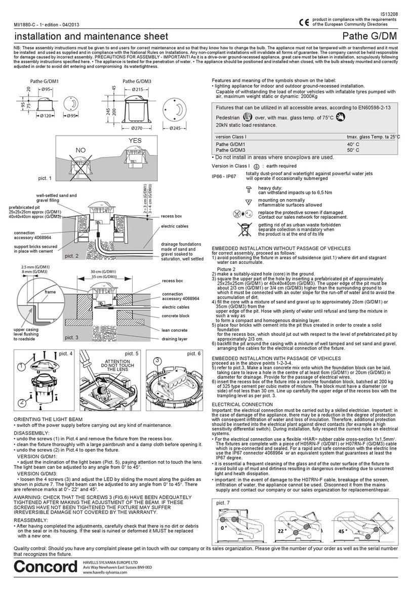
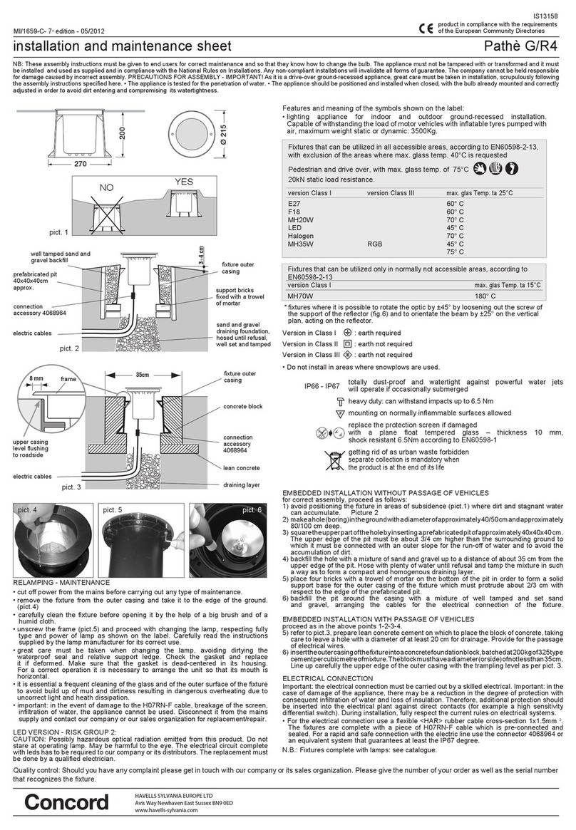
MONTAGE ENCASTRÉ SANS PASSAGE DE VOITURES
pour un montage correct il est nécessaire de procéder comme suit:
1) éviter de positionner l’appareil en dépression (g.1) la où peuvent facilement se
former des dépôts de poussière et des retenues d’eau. Figure 2
2) réaliser un trou (carottage) de taille adéquate dans le sol.
3) mettre d’équerre la partie supérieure du trou en insérant un puits pré-fabriqué de
dimensions environ 25x25x25cm (G/D1), 30x30x30cm (G/D2) ou 40x40x40cm
(G/D3). La partie supérieure du puits devra être installé 2/3 cm (G/D1-2) ou di 3/4
cm (G/D3) au-dessus du terrain environnant auquel devra être raccordé avec une
inclinaison vers l’extérieur an de faciliter le débit d’eau et eviter l’accumulation de
saleté.
4) remplir le carottage avec un mélange de sable et de gravier jusqu’à environ 20cm
(G/D1), 25cm (G/D2) ou 35cm (G/D3) du bord supérieur du puisard. Baigner
abbondamment avec de l’eau jusqu’à ce que le mélange constitue une strate
susamment compacte et homogène.
5) sur le fond du puisard ainsi obtenu, poser quatre briques liées avec du mortier an
de créer une base de support solide pour le corage qui devra déborder d’environ
2/3 cm du puisard préfabriqué.
6) remplir le trou à l’extérieur du puits avec un mélange de sable et de graviers bien
compact en prédisposant les câbles de ligne pour l’alimentation électrique de
l’appareil.
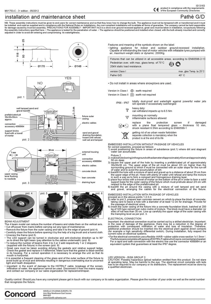
MONTAGE ENCASTRÉ POUR PASSAGE DE VOITURES
procéder comme aux points 1-2-3-4
5) se référer à la gure 3 . Étaler une couche de mortier maigre sur lequel appuyer le
bloc de fondation en laissant au centre un trou d’au moins 6cm (G/D1), 12cm
(G/D2) ou 20cm (G/D3) de diamètre pour le drainage
. Prévoir le passage des câbles
électriques.
6) insérer le puits extérieur de l’appareil dans un bloc de fondation en béton dosé à
200 Kg de ciment type 325 par mètre cube de mélange ayant un diamètre (ou un
côté) non inférieur à 30 mm .
Le bord supérieur du puits extérieur de l’appareil devra être parfaitement nivelé au
plan du sol selon le detail de g.3 .
BRANCHEMENT ÉLECTRIQUE
Attention: la connexion électrique doit être eectuée par un électricien qualié.
Attention: en cas de détérioration de l’appareil, une réduction du degré de protection
peut se produire avec, par conséquent, une inltration d’eau et une réduction de
l’isolement. Il est donc recommandé de prévoir dans l’installation électrique une
protection supplémentaire contre les contacts directs (par exemple, un interrupteur
diérentiel haute sensibilité). Pendant l’installation, respecter scrupuleusement les
normes en vigueur pour les installations.
• Pour la connexion électrique utiliser seulement un câble exible de caoutchouc
<HAR> d’une section de 1x1,5mm 2. Les appareilles sont équipés avec un pièce de
câble H05RN-F (G/D1) ou H07RN-F (G/D2-3) déjà connexe et étanche. Pour une
connexion rapide à la ligne électrique utiliser le connecteur 4068964 ou un système
similaire pour garantir au moins le dégrée IP67.
• il est indispensable d’eectuer régulièrement un nettoyage du verre et de la surface
extérieure de l’appareil sur lequels il ne doit jamais se former des dépôts de terre ou de
saletés. Ces dépôts provoquent en fait un sur échauement empéchant une émission
correcte de la lumière et une bonne dissipation thermique.
• attention: l’appareil ne peut pas être utilisé en cas de détérioration du câble H07RN-F,
de rupture de l’écran, d’inltrations d’eau. Le débrancher et contacter le fabricant ou
le S.A.V. pour le remplacement/réparation.
temp. Max verre avec ta 25°C
40° C
40° C
50° C
40° C
40° C
50° C
Appareils
qui peuvent être utilisés dans toutes les zones accessibles, selon la norme
EN60598-2-13
piétinable , avec une temp. Max. du verre de 75°C
résistent à la charge statique 20kN.
• Ne installer pas en surfaces ou les chasse-neige sont utilisés.
Caractéristiques de l’appareil - signication des symboles portés sur l’étiquette:
• appareil d’éclairage pour montage encastré dans le sol pour l’intérieur et l’extérieur.
Apte à supporter le charge de véhicules avec des pneus gonés avec air, poids
maximum statique ou dynamique: 2000Kg
version Classe I
Pathe G/DD1
Pathe G/DD2
Pathe G/DD3
Pathe G/DQ1
Pathe G/DQ2
Pathe G/DQ3
ORIENTATION DU FAISCEAU LUMINEUX
Attention: Lors de l’installation (carrossable ou pas), vérier l’orientation de l’appareil de
sorte que le faisceau lumineux soit dirigé tel que souhaité ( g. 4 ).
g. 1
OUI
NON
G/DQ
Pathe G/DD1 Pathe G/DD2 Pathe G/DD3
Pathe G/DQ1 Pathe G/DQ2 Pathe G/DQ3
200
245
45
Ø270
Ø 215
Ø215
200
245
45
Ø270
Ø 215
Ø215
93
12 5
32
Ø170
Ø145
Ø145
95
Ø95
Ø 12 0
75 20
Ø 9 5
93
12 5
32
Ø170
Ø145
Ø145
95
Ø95
Ø 12 0
75 20
Ø 9 5
35 cm (G/DM3)
30 cm (G/DM1)
l supérieur du chassis
nivelé au plan du
plancher
bloc de béton
mortier maigre
couche drainante
corage
connexion
accessoire 4068964
câbles de ligne
8 mm (G/DM3)
2.5 mm (G/DM1)
cadre
g. 3
VUE DE DESSUS g. 4
remplissage de sable et de
gravier bien compact
corage
couche de fondation
drainante réalisée avec
sable et gravier, mouillée
jusqu’à saturation, bien
compacte
briques d’appui
xées à l’aide de mortier
connexion
accessoire 4068964
câbles de ligne
2 ÷ 3 cm (G/D1 - G/D2)
3÷ 4 cm (G/D3)
g. 2
puits préfabriqué
25x25x25cm circa (G/D1)
30x30x30cm circa (G/D2)
40x40x40cm circa (G/D3)


