CONCORD Pathe G/DM Series Instruction Manual

HAVELLS SYLVANIA EUROPE LTD
Avis Way Newhaven East Sussex BN9 0ED
www.havells-sylvania.com
installation and maintenance sheet
Quality control: Should you have any complaint please get in touch with our company or its sales organization. Please give the number of your order as well as the serial number
that recognizes the fixture.
Pathe G/DM
product in compliance with the requirements
of the European Community Directories
NB: These assembly instructions must be given to end users for correct maintenance and so that they know how to change the bulb. The appliance must not be tampered with or transformed and it must
be installed and used as supplied and in compliance with the National Rules on Installations. Any non-compliant installations will invalidate all forms of guarantee. The company cannot be held responsible
for damage caused by incorrect assembly. PRECAUTIONS FOR ASSEMBLY - IMPORTANT! As it is a drive-over ground-recessed appliance, great care must be taken in installation, scrupulously following
the assembly instructions specified here. • The appliance is tested for the penetration of water. • The appliance should be positioned and installed when closed, with the bulb already mounted and correctly
adjusted in order to avoid dirt entering and compromising its watertightness.
ORIENTING THE LIGHT BEAM
• switch off the power supply before carrying out any kind of maintenance.
DISASSEMBLY:
• undo the screws (1) in Pict.4 and remove the fixture from the recess box.
• clean the fixture thoroughly with a large paintbrush and a damp cloth before opening it.
• undo the screws (2) in Pict.4 to open the fixture.
VERSION G/DM1:
• adjust the inclination of the light beam (Pict. 5), paying attention not to touch the lens.
The light beam can be adjusted to any angle from 0° to 45°.
VERSION G/DM3:
• loosen the 4 screws (3) and adjust the LED by sliding the mount along the guides as
shown in picture 7. The light beam can be adjusted to any angle from 0° to 45°. There
are reference marks at 0°- 22° and 45°.
AWARNING: CHECK THAT THE SCREWS 3 (FIG.6) HAVE BEEN ADEQUATELY
TIGHTENED AFTER MAKING THE ADJUSTMENT OF THE BEAM. IF THESE
SCREWS HAVE NOT BEEN TIGHTENED THE FIXTURE MAY SUFFER
IRREVERSIBLE DAMAGE NOT COVERED BY THE WARRANTY.
REASSEMBLY:
• After having completed the adjustments, carefully check that there is no dirt or debris
on the seal or in its housing. If the seal is ruined or deformed it MUST be replaced
with a new one.
well-settled sand and
gravel filling
recess box
drainage foundations
made of sand and
gravel soaked to
saturation, well settled
pict. 1
support bricks secured
in place with cement
connection
accessory 4068964
prefabricated pit
25x25x25cm approx
(G/DM1)
40x40x40cm approx
(G/DM3)
electric cables
YES
NO
2÷3 cm
(G/DM1)
3÷4 cm
(G/DM3)
35 cm (G/DM3)
30 cm
(G/DM1)
upper casing
level flushing
to roadside
pict. 7
pict. 4 pict. 5 pict. 6
Pathe G/DM1 Pathe G/DM3
200
245
45
Ø270 Ø245
Ø 215
95
Ø 95
Ø 120 Ø95
75 20
Version in Class I : earth required
IP66 - IP67
totally dust-proof and watertight against powerful water jets
will operate if occasionally submerged
heavy duty:
can withstand impacts up to 6,5 Nm
mounting on normally
inflammable surfaces allowed
replace the protective screen if damaged.
Contact our sales network for replacement.
getting rid of as urban waste forbidden
separate collection is mandatory when
the product is at the end of its life
EMBEDDED INSTALLATION WITHOUT PASSAGE OF VEHICLES
for correct assembly, proceed as follows:
1) avoid positioning the fixture in areas of subsidence (pict.1) where dirt and stagnant
water can accumulate.
Picture 2
2) make a suitably-sized hole (core) in the ground.
3) square the upper part of the hole by inserting a prefabricated pit of approximately
25x25x25cm (G/DM1) or 40x40x40cm (G/DM3). The upper edge of the pit must be
about 2/3 cm (G/DM1) or 3/4 cm (G/DM3) higher than the surrounding ground to
which it must be connected with an outer slope for the run-off of water and to avoid the
accumulation of dirt.
4) fill the core with a mixture of sand and gravel up to approximately 20cm (G/DM1) or
35cm (G/DM3) from the
upper edge of the pit. Hose with plenty of water until refusal and tamp the mixture in
such a way as
to form a compact and homogenous draining layer.
5) place four bricks with cement into the pit thus created in order to create a solid
foundation
for the recess box, which should jut out with respect to the level of prefabricated pit by
approximately 2/3 cm.
6) backfill the pit around the casing with a mixture of well tamped and set sand and gravel,
arranging the cables for the electrical connection of the fixture.
EMBEDDED INSTALLATION WITH PASSAGE OF VEHICLES
proceed as in the above points 1-2-3-4.
5) refer to pict.3, Make a lean concrete mix onto which the foundation block can be laid,
taking care to leave a hole in the centre of at least 6cm (G/DM1) or 20cm (G/DM3) in
diameter for drainage. Provide for the passage of electrical wires.
6) insert the recess box of the fixture into a concrete foundation block, batched at 200 kg
of 325 type cement per cubic metre of mixture. The block must have a diameter (or
side) of not less than 30 cm. Line up carefully the upper edge of the recess box with the
trampling level as per pict. 3.
ELECTRICAL CONNECTION
Important: the electrical connection must be carried out by a skilled
electrician
. Important: in
the case of damage of the appliance, there may be a reduction in the degree of protection
with consequent infiltration of water and loss of insulation. Therefore, additional protection
should be inserted into the electrical plant against direct contacts (for example a high
sensitivity differential switch). During installation, fully respect the current rules on electrical
systems.
• For the electrical connection use a flexible <HAR> rubber cable cross-section 1x1,5mm2.
The fixtures are complete with a piece of H05RN-F (G/DM1) or H07RN-F (G/DM3) cable
which is pre-connected and sealed. For a rapid and safe connection with the electric line
use the IP67 connector 4068964 or an equivalent system that guarantees at least the
IP67 degree.
• it is essential a frequent cleaning of the glass and of the outer surface of the fixture to
avoid build up of mud and dirtiness resulting in dangerous overheating due to uncorrect
light and heath dissipation.
• important: in the event of damage to the H07RN-F cable, breakage of the screen,
infiltration of water, the appliance cannot be used. Disconnect it from the mains
supply and contact our company or our sales organization for replacement/repair.
version Class I
Pathe G/DM1
Pathe G/DM3
tmax. glass Temp. ta 25°C
40° C
50° C
Fixtures that can be utilized in all accessible areas, according to EN60598-2-13
Pedestrian over, with max. glass temp. of 75°C
20kN static load resistance.
• Do not install in areas where snowplows are used.
Features and meaning of the symbols shown on the label:
• lighting appliance for indoor and outdoor ground-recessed installation.
Capable of withstanding the load of motor vehicles with inflatable tyres pumped with
air, maximum weight static or dynamic: 2000Kg
concrete block
lean concrete
draining layer
recess box
connection
accessory 4068964
electric cables
8 mm (P01)
2.5 mm (P2)
8 mm (G/DM3)
2.5 mm (G/DM1)
frame
pict. 2
pict. 3
13
ATTENTION
DO NOT TOUCH
THE LENS
2
MI/1880-C - 1aedition - 04/2013
IS13208

HAVELLS SYLVANIA EUROPE LTD
Avis Way Newhaven East Sussex BN9 0ED
www.havells-sylvania.com
instructions de montage - entretien
Contrôle qualité: Pour toute réclamation, nous vous prions de bien vouloir contacter notre société ou notre organisation de vente, en citant le numéro de commande et le numéro
qui contremarque l’appareil.
Pathe G/DM
produit avec caractéristiques selon les
Directives Communautaires Européennes
NOTA BENE: Remettre obligatoirement ces instructions de montage à l’usager final pour qu’il connaisse les modalités correctes de maintenance et de remplacement d’ampoule. Toute modification et/ou
transformation est interdite sur l’appareil, qui doit être installé et utilisé tel qu’il est fourni et conformément aux Normes d’Installation Nationales. Une installation non conforme provoque la déchéance de
toutes formes de garantie et la compagnie ne répondra pas des dommages provoqués par un montage erroné. PRECAUTIONS DE MONTAGE - AVERTISSEMENTS! Comme l’appareil est charretier et
encastré dans le terrain, exécuter l’installation avec le plus grand soin en respectant scrupuleusement les instructions de montage spécifiées ici. • L’appareil est essayé et testé contre la pénétration de l’eau.
• Mettre l’appareil en position et l’installer fermé avec l’ampoule déjà en place, et correctement orienté pour empêcher l’entrée éventuelle de saleté et ne pas en compromettre l’étanchéité.
ORIENTATION DU FAISCEAU LUMINEUX
• Couper l’alimentation avant tout entretien.
DÉMONTAGE:
• dévisser les vis (1) de Fig.4 et retirer l’appareil du coffrage.
• avant de l’ouvrir, le nettoyer soigneusement avec un gros pinceau et un chiffon humide.
• dévisser les vis (2) de Fig.4 pour ouvrir l’appareil.
VERSION G/DM1:
• ajuster l’inclinaison du faisceau (Fig. 5), attention à ne pas toucher la lentille.
Le faisceau peut être orienté selon une inclinaison comprise entre 0° et 45°.
VERSION G/DM3:
• desserrer les 4 vis (3) et régler la LED en faisant coulisser le support dans les guides
comme le montre la figure 7. Le faisceau peut être orienté selon une inclinaison comprise
entre 0 et 45°. Les repères indiquent 0°- 22° et 45°.
ATTENTION : UNE FOIS LE FAISCEAU RÉGLÉ, VEILLER À BIEN SERRER LES VIS 3
(FIG. 6).
UN SERRAGE INCORRECT DES VIS PEUT ENTRAÎNER DES DOMMAGES
IRRÉVERSIBLES SUR L’APPAREIL QUI NE SONT PAS COUVERTS PAR LA GARANTIE.
REMONTAGE:
• Après avoir terminé le réglage, vérifier soigneusement qu’il n’y ait pas de salissures ou de
débris sur
le joint ou dans son siège. Si le joint est endommagé ou déformé, il DOIT être remplacé
par un nouveau joint.
remplissage de sable et
de gravier bien compact
coffrage
couche de fondation
drainante réalisée avec
sable et gravier, mouillée
jusqu’à saturation, bien
compacte
fig. 1
briques d’appui
fixées à l’aide de
mortier
connexion
accessoire 4068964
puits préfabriqué
25x25x25cm sur (G/DM1)
40x40x40cm sur (G/DM3)
câbles de ligne
OUI
NON
2÷3 cm
(G/DM1)
3÷4 cm
(G/DM3)
35 cm (G/DM3)
30 cm
(G/DM1)
fil supérieur du
chassis nivelé au
plan du plancher
fig. 7
fig. 4 fig. 5 fig. 6
Pathe G/DM1 Pathe G/DM3
200
245
45
Ø270 Ø245
Ø 215
95
Ø 95
Ø 120 Ø95
75 20
Version en Classe I : mise à la terre nécessaire
IP66 - IP67 totalement protégé contre la poussière et violents jets d’eau
étanche pour immersion temporaire
prévu pour situations difficiles,
peut supporter des chocs pas inférieurs à 6,5 Nm
adapté pour utilisation sur des surfaces
normalement inflammables
si l’écran de protection est endommagé, le remplacer.
Pour ce faire, s’adresser à notre réseau de vente
il est interdit l’élimination comme ordure urbaine
le rammassage separé est obligatoir lorsque le produit
est à la fin de sa vie
MONTAGE ENCASTRÉ SANS PASSAGE DE VOITURES
pour un montage correct il est nécessaire de procéder comme suit:
1) éviter de positionner l’appareil en dépression (fig.1) la où peuvent facilement se former
des dépôts de poussière et des retenues d’eau.
Figure 2
2) réaliser un trou (carottage) de taille adéquate dans le sol.
3) mettre d’équerre la partie supérieure du trou en insérant un puits pré-fabriqué de
dimensions environ 25x25x25cm (G/DM1) ou 40x40x40cm (G/DM3). La partie
supérieure du puits devra être installé 2/3 cm (G/DM1) ou di 3/4 cm (G/DM3) au-dessus
du terrain environnant auquel devra être raccordé avec une inclinaison vers l’extérieur
afin de faciliter le débit d’eau et eviter l’accumulation de saleté.
4) remplir le carottage avec un mélange de sable et de gravier jusqu’à environ 20 cm (G/
DM1) ou 35 cm (G/DM3) du bord supérieur du puisard. Baigner abbondamment avec
de l’eau jusqu’à ce que le mélange constitue une strate suffisamment compacte et
homogène.
5) sur le fond du puisard ainsi obtenu, poser quatre briques liées avec du mortier afin de
créer une base de support solide pour le coffrage qui devra déborder d’environ 2/3 cm
du puisard préfabriqué.
6) remplir le trou à l’extérieur du puits avec un mélange de sable et de graviers bien
compact en prédisposant les câbles de ligne pour l’alimentation électrique de l’appareil.
MONTAGE ENCASTRÉ POUR PASSAGE DE VOITURES
procéder comme aux points 1-2-3-4
5) se référer à la figure 3. Étaler une couche de mortier maigre sur lequel appuyer le bloc
de fondation en laissant au centre un trou d’au moins 6 cm (G/DM1) ou 20 cm (G/DM3)
de diamètre pour le drainage
. Prévoir le passage des câbles électriques.
6) insérer le coffrage dans un bloc de fondation en béton dosé à 200 Kg de ciment type 325
par mètre cube de mélange ayant un diamètre (ou un côté) non inférieur à 350 mm .
Le bord supérieur de le coffrage devra être parfaitement nivelé au plan du sol selon le
detail de fig.3.
BRANCHEMENT ÉLECTRIQUE
Attention: la connexion électrique doit être effectuée par un électricien qualifié. Attention:
en cas de détérioration de l’appareil, une réduction du degré de protection peut se produire
avec, par conséquent,
une infiltration d’eau et une réduction de l’isolement. Il est donc recommandé de prévoir
dans l’installation électrique une protection supplémentaire contre les contacts directs (par
exemple, un interrupteur différentiel haute sensibilité). Pendant l’installation, respecter
scrupuleusement les normes en vigueur pour les installations.
• Pour la connexion électrique utiliser seulement un câble flexible de caoutchouc <HAR>
d’une section de 1x1,5mm2. Les appareilles sont équipés avec un pièce de câble
H05RN-F (G/DM1) ou H07RN-F (G/DM3) déjà connexe et étanche. Pour une connexion
rapide à la ligne électrique utiliser le connecteur 4068964 ou un système similaire pour
garantir au moins le dégrée IP67.
• il est indispensable d’effectuer régulièrement un nettoyage du verre et de la surface extérieure
de l’appareil sur lequels il ne doit jamais se former des dépôts de terre ou de saletés. Ces
dépôts provoquent en fait un sur échauffement empéchant une émission correcte de la lumière
et une bonne dissipation thermique.
• attention: l’appareil ne peut pas être utilisé en cas de détérioration du câble H07RN-F,
de rupture de l’écran, d’infiltrations d’eau. Le débrancher et contacter le fabricant ou le
S.A.V. pour le remplacement/réparation.
version Classe I
Pathe G/DM1
Pathe G/DM3
temp. Max verre avec
ta 25°C
40° C
50° C
Appareils
qui peuvent être utilisés dans toutes les zones accessibles, selon la
norme EN60598-2-13
piétinable , avec une temp. Max. du verre de 75°C résistent à la charge
statique 20kN.
• Ne installer pas en surfaces ou les chasse-neige sont utilisés.
Caractéristiques de l’appareil - signification des symboles portés sur l’étiquette:
• appareil d’éclairage pour montage encastré dans le sol pour l’intérieur et l’extérieur.
Apte à supporter le charge de véhicules avec des pneus gonflés avec air, poids
maximum statique ou dynamique: 2000Kg
bloc de béton
mortier maigre
couche drainante
coffrage
connexion
accessoire 4068964
câbles de ligne
8 mm (P01)
2.5 mm (P2)
8 mm (G/DM3)
2.5 mm (G/DM1)
cadre
fig. 2
fig. 3
13
ATTENTION
NE TOUCHER PAS
LA LENTILLE
2

HAVELLS SYLVANIA EUROPE LTD
Avis Way Newhaven East Sussex BN9 0ED
www.havells-sylvania.com
AUSRICHTUNG DES LICHTBÜNDELS
• Vor allen Wartungsmaßnahmen muss die Spannungsversorgung abgeschaltet werden.
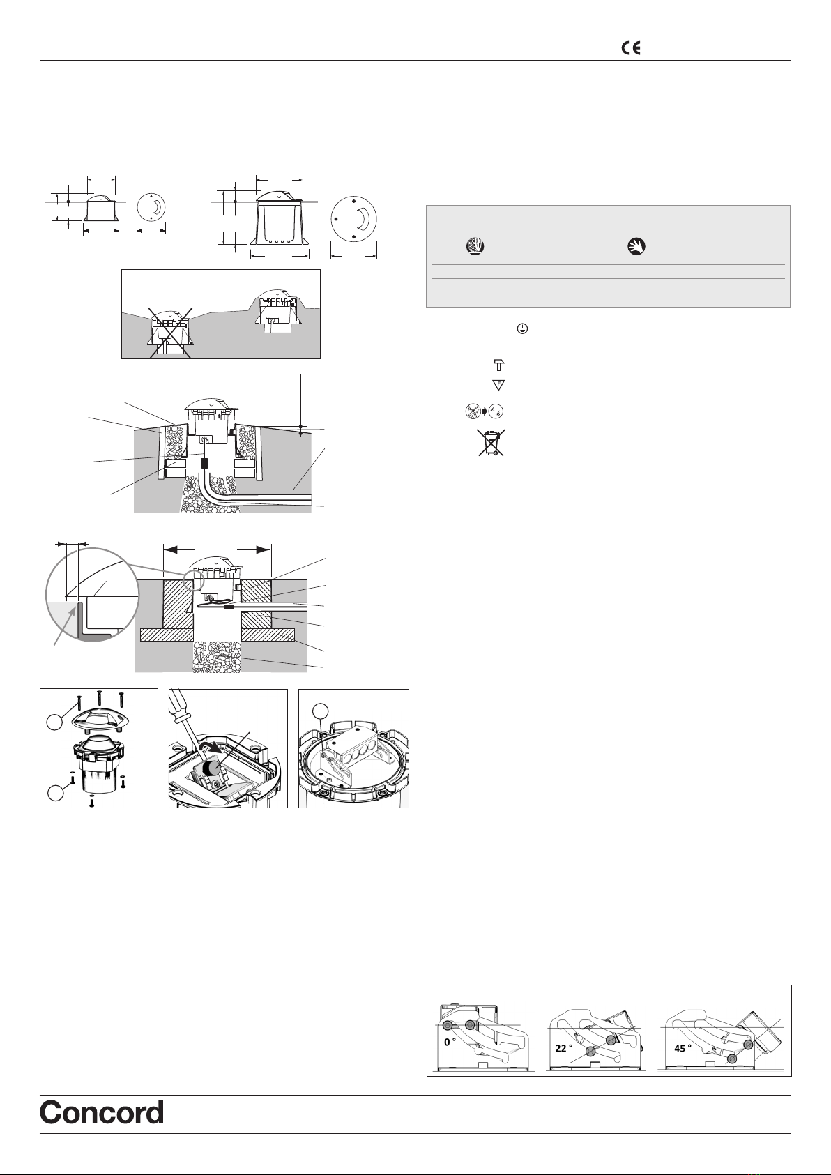
AUSBAU:
• Die Schrauben (1) aus Abb. 4 herausdrehen und die Leuchte aus dem Gehäuse ziehen.
• Die Leuchte mit einem großen Pinsel und einem feuchten Tuch vor dem Öffnen sorgfältig
säubern.
• Die Schrauben (2) aus Abb. 4 zum Öffnen der Leuchte herausdrehen.
VERSION G/DM1:
• Die Neigung des Lichtbündels einstellen (Abb. 5), die Linse nicht anfassen.
Das Lichtbündel kann auf eine Neigung zwischen 0° und 45° ausgerichtet werden.
VERSION G/DM3:
• Die 4 Schrauben (3) lockern und die LED durch Verschieben der Halterung auf den
Schienen wie in Abbildung 7 dargestellt einstellen. Das Lichtbündel kann auf eine Neigung
zwischen 0° und 45° ausgerichtet werden. Die Bezugsmarken geben 0°- 22° und 45° an.
ACHTUNG: PRÜFEN SIE, DASS SIE DIE SCHRAUBEN 3 (ABB. 6) NACH DER REGULIERUNG DES
LICHTBÜNDELS AUSREICHEND FESTGEZOGEN HABEN. WERDEN DIESE SCHRAUBEN NICHT
FESTGEZOGEN, KANN DIES IRREPARABLE SCHÄDEN AN DER LEUCHTE ZUR FOLGE HABEN, DIE
NICHT DURCH DIE GARANTIE ABGEDECKT SIND
.
WIEDEREINBAU:
• Nach Beendigung der Einstellungen genau prüfen, dass kein Schmutz oder Geröll an der
Dichtung oder ihrem Sitz vorhanden ist. Wenn die Dichtung defekt oder verformt ist, MUSS
sie durch eine neue ersetzt werden.
Pathe G/DM
Gut gesetzte Füllschicht
aus Sand und Kies
Gehäuse
Bis zur Sättigung
gewässerter
Drainagegrund aus
Sand und Kies, gut
gesetzt
Abb. 1
Mit Mörtel fixierte
Backsteine als Basis
Anschluss an
Zubehör 4068964
vorgefertigter
Einbauschacht
ca. 25x25x25cm (G/DM1)
ca. 40x40x40cm (G/DM3) Leitungskabeln
JA
NEIN
2÷3 cm
(G/DM1)
3÷4 cm
(G/DM3)
35 cm (G/DM3)
30 cm
(G/DM1)
Montageanleitung - Instandhaltung
obener Faden des
Schachtels auf der
Strasseroberfläche nivelliert
Abb. 7
Abb. 4 Abb. 5 Abb. 6
Pathe G/DM1 Pathe G/DM3
200
245
45
Ø270 Ø245
Ø 215
95
Ø 95
Ø 120 Ø95
75 20
Qualitätskontrolle: Sollten Sie Reklamationen haben, wenden Sie sich an unsere Firma oder an unsere Verkaufsorganisation unter Angabe des Bestelldatums und der
Kennummer des Geräts.
Version in Klasse I : benötigt ein Erdungskabel
IP66 - IP67 Absolut staubdicht Schutz bei Untertauchen
und wasserdicht gegen stärke Wasserstrahle
Belastbarkeit: kann Stösse von einer Kraft bis 6,5 Nm ertragen
Geeignet für Montage auf normal entflammbaren
Befestigungsflächen
Den Schutzschirm bei Beschädigung austauschen.
Setzen Sie sich zum Erhalt eines Ersatzes mit unserem
Vertriebsnetz in Verbindung.
Das Entsorgen im Hausmüll ist verboten!
Bei Ablauf der Lebensdauer bitte beachten:
Abfalltrennung ist Pflicht
MONTAGE UNTER DER ERDE, NICHT BEFAHRBAR
für eine richtige Montage, muss wie folgt vorgegangen werden:
1) d
as Gerät nicht in Senkungen installieren (Abb.1), in denen sich lecht Schmutz und Feuchtigkeit
ansammeln kann.
Abbildung 2
2) Ein Loch (Kernbohrung) geeigneter Größe im Boden vorsehen.
3) Den oberen Teil des Loches mit einer vorgefertigten Verschalung mit einem Ausmass von
25x25x25cm (G/DM1) bzw. 40x40x40cm (G/DM3) verstärken. Der obere Rand der
Verschalung muss
ca. 2/3 cm (G/DM1) bzw. 3/4 cm (G/DM3) aus dem Boden herausragen und abfallende
Flanken nach aussen haben, um das Abfliessen des Wassers zu erleichtern und das
Ansammeln von Schmutz zu vermeiden.
4) Das Loch mit einem Gemisch aus Sand und Kies bis zu einem Abstand von etwa 20
cm (G/DM1) bzw. 35 cm (G/DM3) vom oberen Schachtrand füllen. Reichlich mit Wasser
begiessen, damit sich die
Mischung richtig festsetzt und eine wasserdurchlässige kompakte und gleichmässige
Schicht bildet.
5) Auf dem so erhaltenen Boden des Einbauschachtes vier Backsteine mit Mörtel so fixieren,
dass eine feste Basis für das Gehäuse entsteht, das etwa 2/3 cm über den Rand des
vorgefertigten Einbauschachtes überstehen muss.
6)
Das Loch um das Chassis herum mit einer Mischung aus Sand und Kies ausfüllen, die gut
festgedrückt werden muss, wobei gleichzeitig die Linienkabel des Gerätes für die elektrische
Verbindung ausgerichtet werden müssen.
MONTAGE UNTER DER ERDE, BEFAHRBAR
Die Anweisungen 1-2-3-4 wie oben angegeben befolgen
5) vgl. Abbildung 3, Eine Magerbetonschicht einbringen, auf welcher der Fundamentblock
aufgesetzt wird; dabei darauf achten, dass in der Mitte ein Loch mit einem Durchmesser
von mindestens 6 cm (G/DM1) bzw. 20 cm (G/DM3) für die Drainage gelassen wird. Ein
Durchgang für die Kabeln vorsehen.
6)
Das Chassis des Gerätes in einen Zementboden einlassen, der auf 200 Kg Zement des Typs
325 pro Kubikmeter Mischung bemessen ist.
Der Zementblock muss einen Durchmesser
(oder eine Seite) von mindestens 30 cm haben.
Der obener Rand des aussenes Schachtels
mit der Fußgängeroberflache aufmerksam anpassen.
(Abb.3)
ELEKTROANSCHLUSS
Achtung: die elektrische Verbindung muss von einem qualifizierten Installateur durchgeführt
werden. Achtung: bei Beschädigung der Leuchte kann der Schutzgrad beeinträchtigt
werden mit daraus folgendem Eindringen von Wasser und Isolierungsverlust. Es wird daher
empfohlen, die elektrische Anlage mit einem Zusatzschutz gegen direkte Kontakte (z. B. mit
einem hochempfindlichen Differentialschalter) auszurüsten. Bei der Installation die geltenden
anlagentechnischen Vorschriften unbedingt befolgen.
•
Für die elektrische Verbindung ein flexibles <HAR> Gummikabel mit Querschnitt von 1x1,5mm
2
benützen. Die Geräte sind mit einem Stück H05RN-F (P01) bzw. H07RN-F (P2) Kabel
ausgestattet, der schon verbunden und getestet ist. Für eine schnelle und sichere Verbindung
an der elektrischen Leitung die 4068964 Anschlussstelle oder eine ähnliche verwenden die
einen Grad von mindestens IP67 gewährleistet.
• Das Glas der Leuchte sowie alle Aussenflächen des Gerätes müssen regelmässig
gereinigt werden, so dass Ablagerungen von Schmutz ausgeschlossen sind. Solche
Ablagerungen beinhalten die Gefahr einer Überhitzung und verhindern die Vorschriftsmässige
Lichtabstrahlung und Wärmedissipation.
• Achtung: im Fall von beschädigtem Kabel H07RN-F, Bruch des Schutzschirmes oder
Eindringen von Wasser darf die Leuchte nicht verwendet werden. Schalten Sie die Leuchte
vom Strom ab und kontaktieren Sie unser Unternehmen oder unsere Verkaufsorganisation
für den Austausch oder die Reparatur.
version Klasse I
Pathe G/DM1
Pathe G/DM3
max. Glastemperatur ta
25°C
40° C
50° C
Apparate die in allen zugänglichen Arealen verwendet werden können außer,
nach EN60598-2-13,
Begeh mit max. Glastemperatur 75°C Statische Belastbarkeit 20 kN.
• Nicht in Arealen installieren wo Schneeräumer eingesetzt werden.
Eigenschaften - Bedeutung der Symbole auf dem Typenschild:
• Begehbare Bodeneinbauleuchte für den Innen-und Außenbereich.
Hält das Gewicht von Kraftfahrzeugen mit Gummireifen aufgepumpt mit Luft,
aus maximalen Gewicht statisches oder dynamisches: 2000Kg
Betonblock
Magerschicht
dränierende Schicht
Gehäuse
Anschluss an
Zubehör 4068964
Leitungskabeln
Das Produkt entspricht den Richtlinien
der Europäischen Gemeinschaft
NOTA BENE: Vorliegende Montageanleitungen müssen auf jeden Fall dem Endverbraucher übergeben werden, damit dieser über die korrekten Wartungs- und Lampenaustauschmodalitäten
informiert ist. Jegliches Aufbrechen und/oder Änderung der Leuchte ist verboten. Die Leuchte muss wie geliefert und entsprechend den anlagentechnischen Landesvorschriften montiert und verwendet
werden. Nichtentsprechende Installationen führen zum Verfall von jeglicher Garantie. Das Unternehmen übernimmt keine Verantwortung für Schäden, die durch fehlerhafte Montage verursacht sind.
VORSICHTSMAßNAHMEN FÜR DIE MONTAGE - HINWEISE Da die Leuchte befahrbar und in den Boden eingelassen ist, muss die Montage mit größter Sorgfalt unter strenger Befolgung der hier
erwähnten Montageanleitungen durchgeführt werden. • Die Leuchte ist auf Wassereindringung getestet und geprüft. • Es empfiehlt sich, die Leuchte geschlossen mit bereits montierter Lampe und korrekter
Ausrichtung zu positionieren und zu installieren, um den Eintritt von Schmutz zu vermeiden und die Dichtigkeit nicht zu beeinträchtigen.
8 mm (P01)
2.5 mm (P2)
8 mm (G/DM3)
2.5 mm (G/DM1)
Rahmen
Abb. 2
Abb.3
13
ACHTUNG
ANFASSEN SIE
DIE LINSE NICHT
2
This manual suits for next models
2
Table of contents
Languages:
Other CONCORD Outdoor Light manuals
Popular Outdoor Light manuals by other brands

ROLF
ROLF KERN 1453170 instruction manual

JONATHAN Y
JONATHAN Y JYL3005 installation guide

Heath Company
Heath Company Reflex Dual Brite SL-4180-A manual

VIBIA
VIBIA Swing 0507 Assembly instructions

marset
marset Joan Gaspar TXL 2019 Assembly instructions

Reality Leuchten
Reality Leuchten R4393-87 quick start guide

BSi
BSi iODIN installation guide

Hyundai
Hyundai HSL021701 instruction manual

FLOS
FLOS OK F4640009 Instruction for correct Installation and Use

Winter Wonder Lane
Winter Wonder Lane Lit 2PK Lying Deer Operating and safety instructions

as-Schwabe
as-Schwabe 46978 manual

muuto
muuto PULL LAMP Assembly instruction