Concorde Battery Lifeline User manual

TECHNICAL MANUAL
For
Lifeline®Batteries
Manufactured by:
Concorde Battery Corporation
2009 San Bernardino Road
West Covina, CA 91790
Phone 626-813-1234
Fax 626-813-1235
www.lifelinebatteries.com
Document No. 6-0101
Revision D
April 14, 2014
NOTICE: The technical data contained herein has been reviewed and approved for general
release on the basis that it contains no export controlled information. No part of this document
may be copied or reproduced by any means, including electronic or mechanical, without written
permission from Concorde Battery Corporation.
DISCLAIMER: The technical data contained herein is based upon the best information available
as of the latest revision date. Concorde Battery Corporation makes no warranty of
merchantability, fitness for any particular purpose, or any other warranty, expressed or implied,
with respect to such information, and we assume no liability resulting from its use. It is the
obligation of each user of the product to determine the suitability for any particular application
and to comply with the requirements of all applicable laws regarding use and disposal of this
product.
Copyright © Concorde Battery Corporation 2014

Document No. 6-0101 Rev. D Page 2 of 38
RECORD OF REVISIONS
Revision
Date
Initial Release
10/27/08
Rev. A
3/25/09
Rev. B
9/09/09
Rev. C
7/18/11
Rev. D
4/14/14

Document No. 6-0101 Rev. D Page 3 of 38
SAFETY SUMMARY
DANGER OF EXPLODING BATTERIES
Lead acid batteries can produce explosive mixtures of hydrogen and oxygen. Take the
following precautions:
Never install batteries in an airtight or sealed enclosure and make sure
installation is adequately ventilated.
Charge batteries in accordance with the instructions given in this manual.
Keep all sparks, flames and cigarettes away from batteries.
Connect cables tightly to the terminals to avoid sparks.
Wear proper eye and face protection when installing and servicing batteries.
DANGER OF CHEMICAL BURNS
Lead acid batteries contain sulphuric acid electrolyte which can cause severe burns to
body tissue. Take the following precautions:
Avoid contact of the electrolyte with skin, eyes or clothing.
Never remove or damage vent valves.
In the event of an accident, flush with water and call a physician immediately.
DANGER OF BURNS IF TERMINALS ARE SHORTED
Lead acid batteries are capable of delivering high currents if the external terminals are
short circuited. The resulting heat can cause severe burns and is a potential fire hazard.
Take the following precautions:
Do not place metal objects across battery terminals.
Remove all metallic items such as belt buckles, watches, bracelets and rings
when installing or servicing batteries.
Wear insulating gloves when installing or servicing batteries.
Use insulating tools when installing or servicing batteries.
DANGER OF THERMAL RUNAWAY
Thermal runaway is a condition in which the battery temperature increases rapidly
resulting in extreme overheating of the battery. Under rare conditions, the battery can
melt, catch on fire, or even explode. Thermal runaway can only occur if the battery is at
high ambient temperature and/or the charging voltage is set too high. Take the
following precautions:
Charge batteries in accordance with the instructions given in this manual.
Do not install batteries near heat sources or in direct sunlight that may artificially
elevate their temperature.
Provide adequate air circulation around the batteries to prevent heat build up.

Document No. 6-0101 Rev. D Page 4 of 38
Table of Contents
Chapter 1 - Introduction
1.1 Company Background ……………………………………………………………………………. 5
1.2 Overview of Lifeline®AGM Technology ……………………………………………………….. 5
1.3 About this Manual ………………………………………………………………………………… 5
Chapter 2 - Battery Construction
2.1 Component Description ………………………………………………………………………….. 6
2.2 Battery with Cut Away View ……………………………………………………………………… 8
2.3 Terminal Types ……………………………………………………………………………………. 9
Chapter 3 - Technology Comparison
3.1 Lifeline®versus Flooded Batteries ……………………………………………………………… 10
3.2 Lifeline®versus Gel Batteries …………………………………………………………………… 11
3.3 Lifeline®versus other AGM Batteries ………………………………………………………….. 12
Chapter 4 - Battery Specifications
4.1 Battery Models …………………………………………………………………………………….. 13
4.2 Terminals ……………………………………………………………………………………………13
4.3 Handles …………………………………………………………………………………………….. 13
4.4 Definition of Ratings ………………………………………………………………………………. 13
4.5 Temperature Range ………………………………………………………………………………. 13
4.6 UL Recognition ……………………………………………………………………………………. 13
4.7 Shipping Classification …………………………………………………………………………… 13
Chapter 5 - Commissioning and Servicing Instructions
5.1 Storing ……………………………………………………………………………………………… 14
5.2 Installation ………………………………………………………………………………………….. 14
5.3 Discharging ………………………………………………………………………………………… 18
5.4 Charging ……………………………………………………………………………………………. 19
5.5 Conditioning ………………………………………………………………………………………...20
5.6 Deep Discharge Recovery ……………………………………………………………………….. 21
5.7 Capacity Testing ……………………………………………………………………………………21
5.8 Temperature Considerations …………….……………….……………………………………… 22
5.9 Servicing …………………………………….………………………………………………………23
5.10 Recycling …………………………………….…………………………………………………… 24
Chapter 6 - Safety Information
6.1 Release of Ignitable Gases ………………………………………………………………………. 25
6.2 Acid Exposure ………………………………………………………………………………………25
6.3 Shorting of Terminals …………………………………………………………………………….. 25
6.4 Thermal Runaway …………………………….……………………………………………………25
Appendix A –Glossary
Appendix B –Frequently Asked Questions
Appendix C –Charts and Graphs

Document No. 6-0101 Rev. D Page 5 of 38
CHAPTER 1 - INTRODUCTION
1.1 Company Background
Concorde Battery Corporation was founded in 1977 and is a manufacturer of premium quality
lead acid batteries. Originally, Concorde’s main product emphasis was dry charged and gelled
electrolyte lead acid batteries. In 1985, Concorde developed its valve regulated, absorbent
glass mat [AGM] technology for use in aircraft applications. The success of this technology in
the aviation market has been outstanding. Concorde is now the largest manufacturer of valve
regulated lead acid batteries for both commercial and military aircraft.
In 1986, Concorde further developed the AGM technology for deep cycle applications. This
development effort provided higher energy density (higher capacity) and better cycle life than its
gelled electrolyte battery. Concorde soon discontinued the gel product line and concentrated all
engineering developments on the AGM product line. In 1987, Concorde began supplying the
marine and recreational vehicle market with our deep cycle AGM batteries. Over the years it has
been our design expertise, quality and customer focus that has made Concorde a leader in
providing the best battery available for this market segment. Concorde is committed to the
proposition that the customer deserves the best performing and highest quality product. Our
batteries are tailored to the application rather than make the designer/user settle for what is
available. It is this commitment –to meet the needs of the customer –that sets Concorde apart.
1.2 Overview of Lifeline®AGM Technology
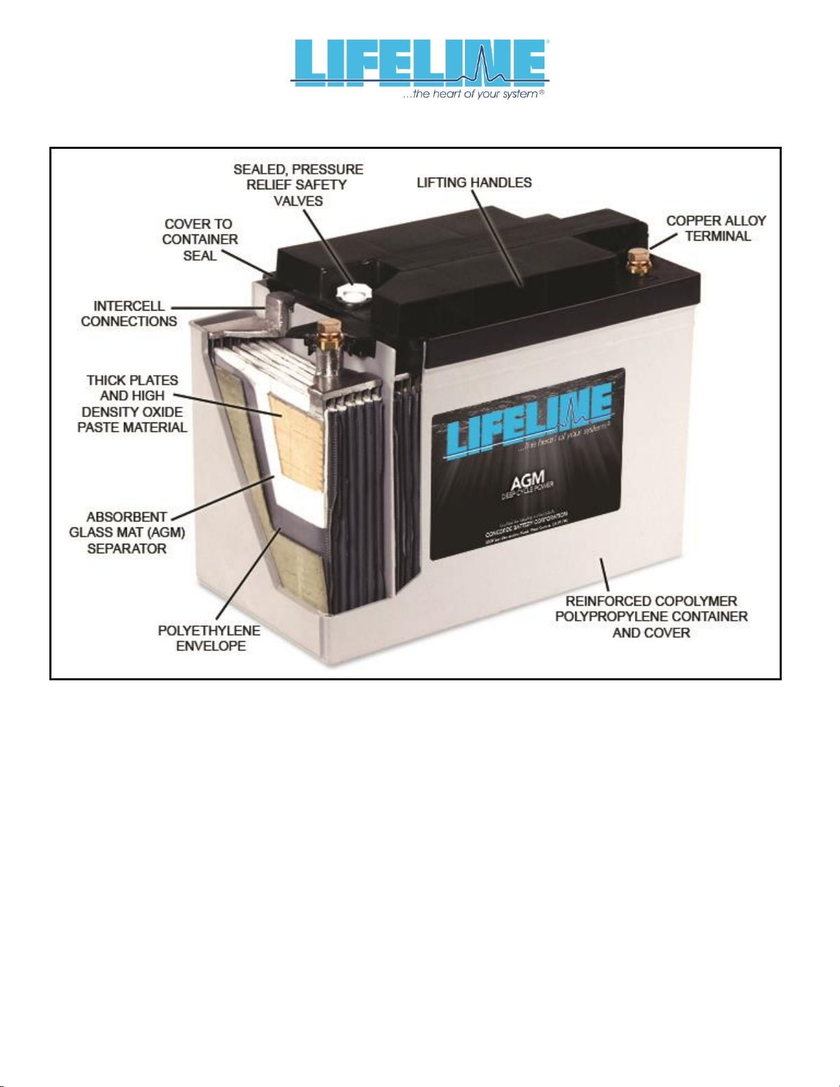
Lifeline® AGM batteries are valve-regulated, recombinant gas, absorbed electrolyte, lead acid
batteries. The cells are sealed with a pressure relief valve that prevents gases within the battery
from escaping. The positive and negative plates are sandwiched between layers of glass mat
consisting of a blend of glass micro fibers of varying length and diameter. This blend features
superior wicking characteristics and promotes maximum retention of the electrolyte. An
envelope of micro porous polyethylene surrounds each wrap of glass mat to further protect the
plates from shorting. Electrolyte is absorbed and held in place by the capillary action between
the fluid and the glass mat fibers. The mat is over 90% saturated with the electrolyte. By design
it is not totally saturated with electrolyte, a portion is filled with gas. This void space provides the
channels by which oxygen travels from the positive to the negative plates during charging.
When the oxygen gas reaches the negative plate, it reacts with lead to form lead oxide and
water. This reaction at the negative plate suppresses the generation of hydrogen that otherwise
would come off the negative plate. In this manner, virtually all of the gas is “recombined” inside
the cell, eliminating the need to add water, resulting in “maintenance free” operation.
Furthermore, since the acid electrolyte is fully absorbed in the AGM separator, the battery is
nonspillable even when turned upside down.
1.3 About this Manual
This manual is intended to provide the customer with technical information for selecting,
installing, operating, and servicing Lifeline® AGM batteries. The next Chapter provides a
detailed description of the product, its design features and materials of construction. Concorde
is very proud of this innovative product line and we think you will share our enthusiasm.
Chapter 3 provides a comparison of Lifeline® with other lead acid technologies: flooded-
electrolyte batteries, gelled-electrolyte batteries, and AGM batteries from other manufacturers.
Chapter 4 presents an overview of the battery specifications for the Lifeline® product line;
detailed specifications for each model are published separately. Chapter 5 provides instructions
for storing, operating and servicing Lifeline® AGM batteries. Chapter 6 gives important safety
information. Further technical information can be found in the Appendices. If you have
additional questions beyond what is covered in this manual, please contact Concorde Battery
Corporation or any of our distributors.

Document No. 6-0101 Rev. D Page 6 of 38
CHAPTER 2 - BATTERY CONSTRUCTION
2.1 Component Description
Refer to the battery pictorial in Section 2.2 showing a cut away view of the cell and a summary
of the features and benefits. A more detailed description of the battery’s construction is given
below.
GRIDS - The negative grid is made of pure lead calcium alloy. The positive grid is extra thick
and is made from a proprietary, pure lead-tin-calcium alloy with special grain refiners. These
features improve corrosion resistance of the grid and gives the battery excellent cycling
capability and float life.
PLATES –The grids are pasted on state-of-the-art pasting machines to give the highest quality
plates with tightly controlled weight and thickness specifications. The lead oxide paste used to
make the positive plates is our high density formula. With time and use, the active material
tends to soften and give less discharge capacity. The high density paste formula retards the
active material softening and extends battery life.
ABSORBENT GLASS MAT [AGM] SEPARATOR –The AGM is a premium blend of glass micro
fibers having an optimum ratio of fine and extra fine fiber sizes. This blend features superior
wicking characteristics and promotes maximum retention of the electrolyte. The AGM layer is
squeezed to an optimum level of compression during assembly to provide sufficient contact with
the surface of the plate over the life of the battery. This compression also promotes retention of
the active material if the battery is exposed to shock or vibration conditions.
POLYETHYLENE ENVELOPE –Concorde is the only manufacturer that envelopes the AGM
separator with a thin layer of microporous polyethylene. The microporous layer is wrapped
around the glass-matted plate and then sealed along the sides to eliminate the possibility of
shorts at the edges of the plate (a common failure mode). The microporous polyethylene is
more durable and puncture resistant than the AGM material alone and significantly reduces the
occurrence of plate to plate shorts.
INTERCELL CONNECTIONS - Massive “over the partition” fusion welds are used which
increase the strength of the intercell connection. This minimizes the possibility of open welds
and provides a low resistance connection between cells. Other manufacturers use “through the
partition” spot welded construction that inserts a weak point into the assembly because of the
small cross section area and the difficulty of making a reliable weld and leak proof construction.
HIGH IMPACT, REINFORCED CONTAINER & COVER –The battery container and cover are
made of a thick walled polypropylene copolymer. This material provides excellent impact
resistance at extreme low temperatures and minimizes bulging at high temperatures.
COVER-TO-CONTAINER SEAL - The batteries use an epoxy-filled tongue and groove seal
between the cover and container. Most other manufacturers heat seal their cover to the
container. The epoxy-filled tongue and groove seal is a far stronger than a heat seal and will not
separate in high or low temperature extreme applications.

Document No. 6-0101 Rev. D Page 7 of 38
PRESSURE RELIEF SAFETY VALVE - Each cell in the battery employs a pressure relief safety
valve. The valve is designed to release excess pressure that builds up over time to vent the
small quantity of gasses that do not recombine inside of the battery. Once the pressure is
released, the valve automatically re-seals. The gasses that escape are mainly oxygen and
some hydrogen, and these gasses rapidly dissipate into the atmosphere.
TERMINALS - Lifeline® AGM batteries are available in a variety of terminal configurations.
Most terminal types are made of copper alloy which provide a long lasting, low resistance
electrical connection. The copper alloy terminals are non corrosive, unlike lead terminals.
Additionally, the copper alloy terminals offer increased environmental protection and personal
safety in comparison to commonly used lead terminals. Refer to the pictorial in Section 2.3 to
see a detailed view of the various terminal types that are available.
HANDLES –Lifting handles are incorporated into all Lifeline® AGM batteries. This provides
easier handling for lifting, carrying and installation.

Document No. 6-0101 Rev. D Page 8 of 38
2.2 Battery with Cut Away View

Document No. 6-0101 Rev. D Page 9 of 38
2.3 Terminal Types

Document No. 6-0101 Rev. D Page 10 of 38
CHAPTER 3 - TECHNOLOGY COMPARISON
3.1 Lifeline®versus Flooded Batteries
Flooded-electrolyte lead acid batteries have been around since 1859 and tend to be less
expensive than AGM or Gel batteries. However, they have major deficiencies compared to
AGM or Gel batteries. For instance, deep cycle flooded lead acid batteries contain antimony in
the grid alloy which causes a high rate of self discharge and rapid water loss due to gassing
reactions. The escape of hydrogen and oxygen from the battery represents a serious safety
hazard if the gasses are not ventilated properly. In flooded batteries, replacing the antimony
lead alloy with calcium lead alloy reduces the amount of gassing and water loss, but the cycle
life is much lower and they are no longer considered deep cycle batteries.
Electrolyte stratification can occur in all types of flooded batteries. As the battery is discharged
and charged, the concentration of acid becomes higher at the bottom of the cell and becomes
lower at the top of the cell. The low acid concentration reduces capacity at the top of the plates,
and the high acid concentration accelerates corrosion at the bottom of the plates and shortens
the battery life. Although stratification can be minimized by raising the charging voltage so that
the increased gassing agitates the electrolyte, this will accelerate the water loss and watering
frequency.
One other difference is that flooded batteries can not tolerate freezing temperatures when in the
discharged state, whereas AGM batteries are not damaged by freezing temperatures. The
following table provides a side by side comparison of Lifeline® AGM and flooded deep cycle
batteries.
Table 3-1. Comparison of Lifeline® AGM Batteries with Flooded Deep Cycle Batteries
Characteristic
Lifeline®AGM Battery
Flooded Deep Cycle Battery
Self Discharge
1 to 3% per month –remains
stable over life.
5-10% per month when new –
increases drastically with age
due to antimony contamination of
the negative plate.
Water Addition
Never.
Frequent –increases
dramatically with age due to
antimony contamination of the
negative plate.
Hydrogen Gas Emissions
Negligible unless severely
overcharged.
Significant volume is generated
and must be ventilated to prevent
explosion.
Electrolyte Spillage
Nonspillable in all orientations –
electrolyte is retained in AGM
separator.
Spills when tilted, inverted, or
cracked.
Electrolyte Stratification
No stratification occurs.
Stratification occurs when
operated at low charging
voltages or in taller batteries.
Tolerance to freezing
temperatures
Resistant to damage when
frozen.
Battery destroyed when frozen.

Document No. 6-0101 Rev. D Page 11 of 38
3.2 Lifeline®versus Gel Batteries
Gel batteries have been commercially available since the early 1970’s and are still offered by
some manufacturers. Concorde manufactured gel batteries for many years before developing
the AGM technology and, therefore, is aware of inherent deficiencies associated with gel
batteries.
The gel product employs a highly viscous, semisolid mixture of silica gel and dilute sulfuric acid
in a colloidal suspension as an electrolyte. The electrolyte is difficult to keep homogeneous and
the solid silica can separate from the acid, creating a “flooded” battery. Handling and vibration
exposure are operational factors that can cause the silica and acid mixture to separate as there
is no chemical bond. In high temperature environments, the semisolid electrolyte develops
cracks and voids that reduce contact between the plates and causes the battery to lose
capacity. This same effect gradually occurs even at normal room temperatures.
By contrast, AGM batteries employ a glass micro fiber mat separator that holds the liquid
electrolyte like a sponge. Shrinkage of the separator does not occur as the battery ages and the
electrolyte remains in direct contact with the plates. The electrolyte remains immobilized even
when the battery is exposed to severe vibration, so electrolyte spillage or leakage is prevented.
Since it is easier to fill a container with a liquid than a semi-solid, AGM batteries require less
space between battery plates. The closer plate spacing gives the AGM battery a lower internal
resistance, making it more charge efficient and giving better power performance on discharge,
especially at low temperatures.
Gel batteries are also more sensitive to charging voltage. If the charging voltage is not
controlled within a very tight range relative to the battery’s temperature, the life of the battery will
be adversely affected. For example, one manufacturer of gel batteries claims that if the charging
voltage is 0.7V higher than the recommended level, the cycle life will be reduced by 60 percent.
The reason for this effect is the limited oxygen recombination capability of gelled batteries.
Lifeline® AGM batteries are more forgiving in overcharge conditions and their ability to
recombine the hydrogen and oxygen gases back into water is more efficient. With Lifeline®
AGM batteries, tests have shown that increasing the charging voltage 1.0V above the
recommended charging voltage results in only a 23% reduction in the cycle life.
The charge acceptance of gel batteries is also less than that of Lifeline® AGM batteries. This
means it takes longer to recharge gel batteries. As an example, tests have shown that when
discharged to 50% of rated capacity (fairly common in a deep cycle applications), gel batteries
took twice as long to reach full charge as compared to Lifeline® AGM batteries.
The following table provides a side by side comparison of Lifeline® AGM and gel batteries:

Document No. 6-0101 Rev. D Page 12 of 38
Table 3-2. Comparison of Lifeline® AGM Batteries with Gel Batteries
Characteristic
Lifeline® AGM Battery
Gel Batteries
Electrolyte Stability
Excellent –AGM acts like a flexible
sponge.
Prone to solid / liquid separation leading
to spillage / spewage of acid and
premature failure. Electrolyte loses
contact with plates due to cracks and
voids as the battery ages, especially at
higher ambient temperatures.
High Rate Performance
Excellent due to low internal
impedance.
Inferior. Plate spacing must be greater to
allow for gel passage during filling. Gel
adds to impedance, especially at low
temperatures.
Sensitivity to Charging
Voltage Levels
Moderately sensitive. Life is
somewhat reduced if charged
outside of recommended charge
voltage levels.
Very Sensitive. Life is greatly reduced if
charged outside of recommended charge
voltage levels.
Charge Acceptance Rate
Excellent. Battery can be fully
charged in 2 hours if high inrush
current is available.
Inferior. Must limit in rush current and
charge time is at least twice as long to
reach full charge.
3.3 Lifeline®versus other AGM Batteries
Lifeline® AGM batteries have been specifically designed for true deep cycle, long service life
capability in adverse temperature and handling conditions. Concorde uses extra thick positive
plates, high density paste, thick AGM separator layers encased within a microporous
polyethylene envelope, thick walled containers with epoxy-sealed covers. A side by side
comparison of Lifeline® AGM batteries with typical AGM batteries from other manufacturers is
provided in the following table:
Table 3-3. Comparison of Lifeline® AGM Batteries with Other AGM Batteries
Characteristic
Lifeline®AGM Battery
Other AGM Batteries
Positive Grids
Extra thick grids (typically 0.095” or
greater) and extra thick plates
(typically 0.105” or greater), for long
cycle and float life.
Thinner grids, typically 0.045 to 0.060”.
Pasted Plates
High density positive paste for long
cycle life.
Lower density, resulting in lower cycle
life.
AGM Separator
Extra thick for maximum electrolyte
reserve. Premium grade of AGM with
extra fine fibers for long life.
Thinner material used. Inferior grade of
AGM without the extra fine fiber content.
Microporous polyethylene
separators
Envelopes the positive plate to
prevent shorting due to shock,
vibration and dendrites
Not present, AGM is the only separator
protecting the plates.
Intercell connections
Massive over the partition connectors
provide a robust, leak proof
connection with low voltage loss.
Inferior through the partition welds have
less cross sectional area, provide
weaker structural connection, and are
leak prone.
Battery Terminals
Copper alloy –low electrical
resistance and no exposed lead.
Lead alloy - higher in electrical
resistance and user is exposed to lead
contamination.
Container
Thick wall for rigid support of cell
elements and high compression of
AGM separator.
Thinner walls, less support of cell
elements and lower compression of
AGM separator.
Cover Seal
Cover is epoxied to container –high
strength bond for reliable operation at
temperature extremes.
Cover is heat sealed (melted) to
container –prone to separation and
leakage at temperature extremes.

Document No. 6-0101 Rev. D Page 13 of 38
CHAPTER 4 - BATTERY SPECIFICATIONS
4.1 Battery Models
The Lifeline® Series consists of deep cycle as well as engine starting batteries. Capacities of
the deep cycle batteries range from 33 to 1200 ampere hours (rated at the 20 hour rate) and a
variety of 2-volt, 6-volt and 12-volt models are available. Ratings of the starting batteries range
from 550 amperes to 810 amperes (CCA at 0°F) and these are only available in 12 volt models.
Refer to the battery specification sheet (published separately) for a complete listing of the
mechanical and electrical specifications for each battery model.
4.2 Terminals
Standard Terminals:The following table shows the standard type of terminal used on each
battery model: Table 4-1. Battery Terminals
Battery Model
Standard Terminal Type
GPL-24T, GPL-2400T, GPL-27T,
GPL-2700T, GPL-31T, GPL-3100T, GPL-31XT, GPL-31T-2V
Marine Terminal (Copper Alloy)
Positive = M10 and Negative = M8
GPL-4DL, GPL-8DL
L-Blade Terminal (Copper Alloy) with M8 Hardware
GPL-4DA, GPL-8DA
SAE Automotive Post (Lead)
GPL-1400T, GPL-30HT, GPL-4CT, GPL-6CT, GPL-L16T,
GPL-4CT-2V, GPL-6CT-2V, GPL-L16T-2V
M8 Threaded Insert (Copper Alloy)
GPL-U1T
M6 Threaded Insert (Copper Alloy)
Optional Terminals: The 2 and 6 volt models are available with marine terminals on a special
order basis.
Terminal Hardware: When requested, batteries are supplied with silicon bronze bolts, nuts and
washers as required for installation.
Terminal Torque Values:Use 35 in-lbs / 4.0 nm for M6. Use 70 in-lbs / 7.9 nm for M8 and M10.
4.3 Handles
All batteries include lifting handles, either built into the cover, dual ropes attached to the cover,
or a single plastic handle attached to brackets on the sides of the container.
4.4 Definition of Ratings
Capacity ratings are after 15 cycles per BCI specifications and are stated at 77°F (25°C) to 1.75
volts per cell.
4.5 Temperature Range
Storage (when fully charged): -67°F (-55°C) to 122°F (50°C)
Operating: -40°F (-40°C) to 160°F (71°C).
4.6 UL Recognition
All Lifeline® AGM batteries meet the requirements of UL®1989 (Standby Battery) and are UL
recognized under UL File Number MH-17983.
4.7 Shipping Classification
Lifeline® AGM batteries have been tested and determined to be in compliance with the
vibration and pressure differential tests in accordance with DOT 49 CFR 173.159(d) and Special
Provision A67 of the International Air Transport Association (IATA) Dangerous Goods
regulations. As such, they are classified as a “NONSPILLABLE BATTERY” and can be shipped
as non-hazardous material by any means. To comply with DOT shipping regulations, the battery
must be packaged to protect against short circuits and the battery and outer packaging must be
plainly and durably marked “NONSPILLABLE” or “NONSPILLABLE BATTERY”.

Document No. 6-0101 Rev. D Page 14 of 38
CHAPTER 5 - COMMISSIONING AND SERVICING INSTRUCTIONS
5.1 Storage
Lifeline® Batteries are charged at the factory and are ready for installation when they are
received. Batteries may be stored prior to installation for up to 2 years, provided they are boost
charged as described below. Batteries should be stored in the coolest environment available,
preferably not exceeding 68°F (20°C). The higher the temperature, the faster the battery will
self-discharge and require boost charging. See Appendix C for data on storage time versus
temperature.
While in storage, batteries should be boost charged every 90 days or when the open circuit
voltage (OCV) drops to 12.5 volts for a 12 volt battery (6.25 volts for a 6 volt battery and 2.08
volts for a 2V battery). This OCV corresponds to approximately 75% state of charge. Boost
charge batteries using a constant voltage charger set at 14.4 to 15.0 volts for a 12 volt battery
(7.2 to 7.5 volts for a 6 volt battery and 2.40 to 2.50 for a 2 volt battery). The boost charge
should be applied until the charging current falls below 0.5 percent of the battery’s 20 hour rated
capacity (0.5 amps for a 100 Ah battery).
5.2 Installation
Be sure there is adequate ventilation in the area where the batteries are to be installed (see
Chapter 6). Batteries may be installed in any orientation except upside down (i.e., terminals
facing the earth). The space surrounding adjacent batteries should be at least 0.25 inch to
permit airflow around each battery. Always use batteries of the same size and condition in multi-
battery installations. When replacing batteries, it is best to replace the entire set of batteries so
they remain balanced.
Connect batteries using cabling that is sized for the maximum load of the system. The voltage
drop on the cables during charging should not exceed 0.2 volts at full output. Protect the battery
terminals from shorting during installation.
Batteries may be connected in series (voltage adds, capacity stays the same), in parallel
(capacity adds, voltage stays the same), or a combination of series and parallel (voltage and
capacity adds). Each of these connection options are illustrated in Figures 5-1 through 5-3,
respectively.

Document No. 6-0101 Rev. D Page 15 of 38
Figure 5-1. Series Connection
Figure 5-2. Parallel Connection
Figure 5-3. Series/Parallel Connection

Document No. 6-0101 Rev. D Page 16 of 38
Connection options for 4-terminal batteries are illustrated in Figures 5-4 through 5-8. For low
rate applications (current levels less than 400 amperes), only two of the four terminals need to
be connected, but it is still best to use all four terminals for redundancy. For high rate
applications (current levels greater than 400 amperes), all four terminals should be connected.
Figure 5-4. Series Connection for 4-Terminal Batteries (Low Rate Applications Only)
Figure 5-5. Series Connection for 4-Terminal Batteries (Low or High Rate Applications, Option A)
Figure 5-6. Series Connection for 4-Terminal Batteries (Low or High Rate Applications, Option B)

Document No. 6-0101 Rev. D Page 17 of 38
Figure 5-7. Series/Parallel Connection for 4-Terminal Batteries (Low Rate Applications Only)
NOTE: Cables A, B and C carry different current levels and should be sized accordingly.
In this example, the current in Cable B is 2 times that of Cable A and the current in
Cable C is three times that of Cable A.

Document No. 6-0101 Rev. D Page 18 of 38
Figure 5-8. Series/Parallel Connection for 4-Terminal Batteries (Low or High Rate Applications)
5.3 Discharging
Discharge data for Lifeline® AGM batteries are given in Appendix C. The capacity delivered by
the battery depends on the rate of discharge as well as the battery temperature. The battery will
deliver less capacity as the discharge rate increases and less capacity as the temperature is
lowered. Graphs are provided in Appendix C to quantify these effects. Peukert plots (Amps vs
Time) are also included, along with formulas for calculating the current that can be removed or
any discharge time from 0.5 hours to 120 hours. To calculate the discharge time for a specified
amperage, these formulas can be inverted as follows:
A = C x T -n
T = C1/n x A-1/n
(A = Amps, T = Time in hours, C & n are constants specific for each battery model)
In general, batteries should be sized such that the rated capacity is at least twice the capacity
required by the load. For example, if 100 Ah is required on average, select at least a 200Ah
battery. This approach will limit the average depth of discharge to 50% and will dramatically
extend the life of the battery (see chart of Cycle Life versus Depth of Discharge in Appendix C).

Document No. 6-0101 Rev. D Page 19 of 38
5.4 Charging
Charging Lifeline® AGM batteries is a matter of replacing the energy removed during discharge
plus a little extra to make up for charging inefficiency. The amount of energy necessary for
complete recharge depends on the depth of discharge, rate of recharge, and temperature.
Typically, between 102% and 110% of the discharged ampere-hours must be returned for full
recharge.
The most efficient method of charging Lifeline® AGM batteries is to use a 3 stage charging
profile. In the first stage, a constant current is applied until the voltage reaches a pre-set limit.
The first stage is often called the Bulk charging stage. In the second stage, the voltage is held
constant at the same pre-set limit until the charging current tapers to a very low value, at which
point the battery is fully charged. The second stage is often called the Absorption charging
stage. A voltage limit of 14.3 volts ± 0.1 volts (7.15 ± 0.05 volt for a 6 volt battery) should be
used when the battery temperature is 77°F (25°C). The battery is fully charged when the
current drops below 0.5% of the battery’s rated capacity (0.5A for a 100Ah battery). In the third
stage, the charging voltage is reduced to a lower value that minimizes the amount of
overcharge, while maintaining the battery at 100% state of charge. This third stage is often
called the Float charging stage. A float voltage of 13.3 ± 0.1 volts (6.65 ± 0.05 volts for a 6 volt
battery) should be used when the battery temperature is 77°F (25°C). The charging voltages at
other temperatures can be determined from the following table:
Table 5-1. Charging Voltage at Different Temperatures for a 12 Volt Battery*
Temp °F
Absorption
Voltage
Float
Voltage
Temp °F
Absorption
Voltage
Float
Voltage
-40
16.88
15.86
70
14.41
13.39
-30
16.58
15.56
77
14.30
13.30
-20
16.30
15.28
80
14.27
13.25
-10
16.03
15.01
90
14.15
13.13
0
15.78
14.76
100
14.04
13.02
10
15.54
14.52
110
13.95
13.00
20
15.31
14.29
120
13.87
13.00
30
15.10
14.08
130
13.81
13.00
40
14.90
13.88
140
13.76
13.00
50
14.72
13.70
150
13.73
13.00
60
14.56
13.54
160
13.71
13.00
* For a 6 volt battery, divide the voltage by 2. For a 2 volt battery, divide the voltage by 6.
The charging current during the Bulk stage should be set as high as practical; higher current
levels mean faster recharge time. Due to the low impedance design, Lifeline® batteries can
tolerate in-rush current levels as high as 5C (500A for a 100Ah battery). The time to reach full
charge at temperatures in the range of 68 to 86°F (20-30°C) can be estimated from the following
equation:
Time to Reach Full Charge = [(DOD/100) x Rated Capacity (Ah) ÷ Rated Output of Charger
(Amp)] + 2 hours.
For example, charging a 100Ah battery at 50% DOD with a 25A charger would take:
[(50/100) x 100 ÷ 25] + 2 = 4 hours to reach full charge.
If a 10A charger is used, it would take:
[(50/100) x 100 ÷ 10] + 2 = 7 hours to reach full charge.

Document No. 6-0101 Rev. D Page 20 of 38
Note that the above formula is approximate and the full charge state should be verified using the
criteria given above (current drops below 0.5% of rated capacity). If the recharge does not
return 102% to 110% of the discharged capacity, the battery’s state of charge will gradually
“walk down” as it is cycled leading to premature failure. Therefore, it is important to verify that
the battery is not being undercharged.
For repetitive deep cycling applications (deeper than 50% DOD), chargers should have an
output current of at least 0.2C (20 Amps for a 100 Ah battery). If the output current is less than
this value, the cycle life of the battery may be negatively affected. If a charger with at least 0.2C
output is not practical, an alternative charge profile using a low rate constant current stage at
the end of the absorption stage will normally improve the cycle life. The constant current stage
should be at 0.02C (2 Amps for a 100Ah battery) for no more than one hour.
Some types of battery chargers allow the user to input the Peukert constant to obtain an
optimum charging profile. For Lifeline® batteries, the recommended value of the Peukert
constant is n = 1.12.
5.5 Conditioning
Conditioning should only be done when the battery is showing symptoms of capacity loss due to
extended time in a partial or low state of charge condition. This could be caused, for example,
by low charging voltage for an extended number of charge cycles, or by repeatedly charging to
only 90% state of charge.
NOTE: Some chargers use the term Equalizing Charge instead of Conditioning Charge. An
Equalizing Charge is generally applied to flooded lead acid batteries that are susceptible to acid
stratification. However, an Equalizing Charge may be used to provide a Conditioning Charge for
Lifeline® batteries as described below.
To apply a conditioning charge, first go through the normal charge cycle to bring the battery to
full charge. The conditioning charge should then be applied by charging for 8 hours. At 77°F
(25°C), the conditioning voltage should be set at 2.58 VPC (15.5 volts for a 12 volt battery). The
conditioning voltage at other temperatures is shown in Table 5-2. By using the temperature-
compensated conditioning voltage, batteries that are not in controlled temperature environments
may be conditioned without bringing them to room temperature. If temperature compensation is
not available, it is best to bring the battery as close to room temperature as possible before
applying the conditioning charge.
Table 5-2. Conditioning Voltage at Different Temperatures for a 12 Volt Battery*
Temperature °F
Conditioning
Voltage
Temperature °F
Conditioning
Voltage
-40
18.05
70
15.58
-30
17.75
77
15.48
-20
17.47
80
15.44
-10
17.20
90
15.32
0
16.95
100
15.21
10
16.71
110
15.12
20
16.48
120
15.04
30
16.27
130
14.98
40
16.07
140
14.93
50
15.89
150
14.90
60
15.73
160
14.88
* For a 6 volt battery, divide the voltage by 2. For a 2 volt battery, divide the voltage by 6.
Table of contents
Other Concorde Battery Camera Accessories manuals