Power-Blox PBX-200 PB User manual

Swarm-enabled Solar Battery System
Installation and operating instructions
PBX-200 Pb
PBX-200 Li
PBX-200 Li/LE
EN
06-2020

Installation and Operating Instructions PBX-200 Pb ; Li ; Li/LE Page 2
Table of contents
1INTRODUCTION AND GENERAL................................................................................................................... 4
1.1 FOREWORD .......................................................................................................................................................4
1.2 CONTACT DETAILS...............................................................................................................................................5
1.3 EXPLANATION OF SYMBOLS...................................................................................................................................5
1.4 GENERAL SAFETY INSTRUCTIONS ...........................................................................................................................5
2SCOPE OF DELIVERY, TRANSPORT AND STORAGE........................................................................................ 7
2.1 AVAILABLE VERSIONS...........................................................................................................................................7
2.2 SCOPE OF DELIVERY.............................................................................................................................................7
2.3 STORAGE AND TRANSPORT ...................................................................................................................................7
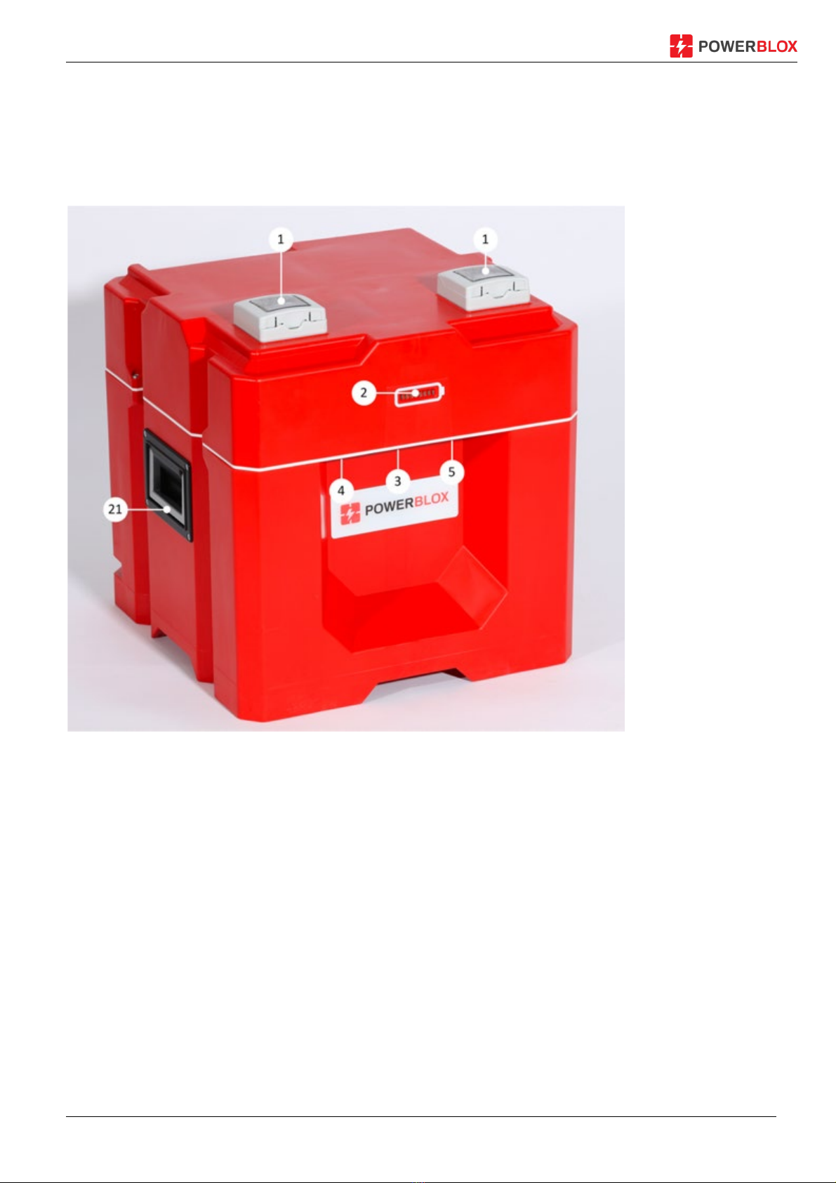
3OVERVIEW OF THE PBX-200 ....................................................................................................................... 8
4PROPERTIES AND TECHNICAL DATA...........................................................................................................11
4.1 PBX-200 PICTORIAL SCHEMATIC .........................................................................................................................14
5SAFETY AND ACCIDENT PREVENTION.........................................................................................................15
5.1 PERSONNEL .....................................................................................................................................................15
5.2 PROTECTION AGAINST ELECTRIC SHOCK.................................................................................................................15
5.3 INFORMATION ABOUT THE BATTERIES...................................................................................................................16
5.3.1 Approved battery types............................................................................................................................16
5.3.2 Protective equipment...............................................................................................................................17
5.3.3 Potential hazards of AGM lead-acid batteries (PBX-200 Pb)...................................................................17
5.3.4 First aid measures for AGM lead acid batteries (PBX-200 Pb).................................................................18
5.3.5 Measures in case of accidental release of lead acid................................................................................18
5.3.6 Potential hazards of LiFePO4 batteries (PBX-200 Li) ...............................................................................18
5.3.7 First aid measures for LiFePO4 batteries Electrolyte (PBX-200 Li)...........................................................18
5.3.8 Measures in case of accidental release of LiFePO4 batteries Electrolyte ................................................19
5.4 IN CASE OF FIRE ................................................................................................................................................19
5.4.1 General notes...........................................................................................................................................19
5.4.2 Fire fighting measures for AGM lead-acid batteries (PBX-200 Pb)..........................................................19
5.4.3 Fire fighting measures for LiFePO4 batteries (PBX-200 Li) ......................................................................19
6INSTALLATION AND COMMISSIONING.......................................................................................................20
6.1 GENERAL.........................................................................................................................................................20
6.2 SITE CONDITIONS ..............................................................................................................................................21
6.3 CONNECTING THE SOLAR MODULE TO THE PBX-200 ..............................................................................................22
6.3.1 Plug mounting of the solar connection....................................................................................................23
6.4 COUPLING OF PBX-200.....................................................................................................................................24
6.5 MINIMUM DISTANCES .......................................................................................................................................26
6.6 INTERCONNECTING SEVERAL TOWERS TO FORM A "POWER WALL"............................................................................27
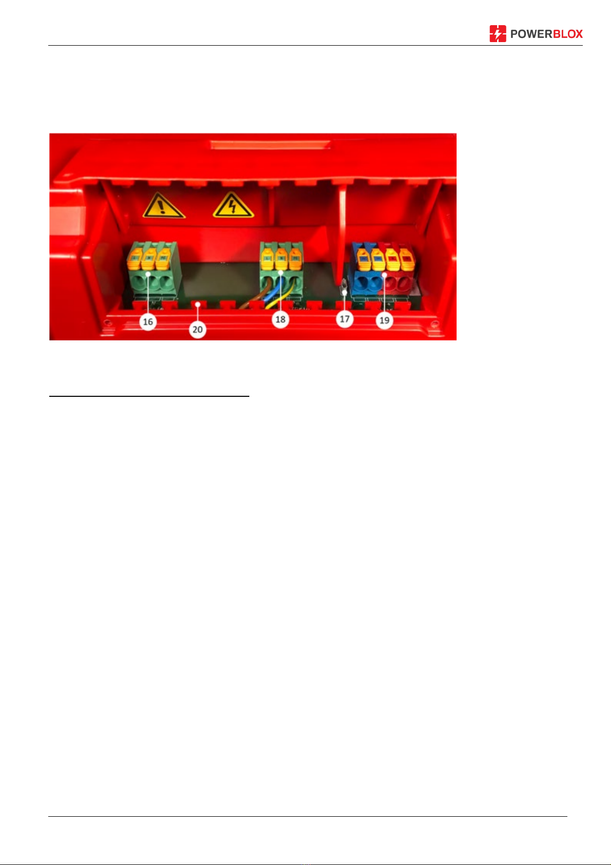
6.7 USE OF THE CONNECTION TERMINALS...................................................................................................................27
6.7.1 Connecting the terminal cables ...............................................................................................................29
6.8 INTERCONNECTION TYPES...................................................................................................................................30
6.8.1 Solar-powered PBX-200 ...........................................................................................................................31
6.8.2 Solar and network operated PBX-200......................................................................................................31
6.8.3 Backup system .........................................................................................................................................32
6.8.4 Combined solar / grid system with connection to the terminal blocks....................................................32
6.9 INSTALL PBX-200.............................................................................................................................................33
6.9.1 Installation of a single PBX-200 ...............................................................................................................33
6.9.2 Installation of additional PBX-200s to a tower or Power Wall (maximum 9 units).................................33
6.9.3 Installation of power systems larger than nine PBX-200.........................................................................34
7OPERATION ..............................................................................................................................................35
7.1 IMPORTANT NOTES BEFORE COMMISSIONING ........................................................................................................35
7.2 LED DISPLAY ....................................................................................................................................................35

Installation and Operating Instructions PBX-200 Pb ; Li ; Li/LE Page 3
7.2.1 Battery charge level indicator..................................................................................................................35
7.2.2 Display of the battery status....................................................................................................................36
7.2.3 Display during synchronization................................................................................................................36
7.2.4 Display on overheating ............................................................................................................................36
7.2.5 Display in case of fault .............................................................................................................................36
7.3 IMPORTANT ASPECTS OF HANDLING BATTERIES ......................................................................................................37
7.3.1 Lead-acid batteries (Type AGM) ..............................................................................................................37
7.3.2 Li batteries (type LiFePO4) .......................................................................................................................37
8MAINTENANCE .........................................................................................................................................38
8.1 CLEANING THE HOUSING ....................................................................................................................................38
8.2 BATTERY .........................................................................................................................................................38
9REPAIR AND TROUBLESHOOTING ..............................................................................................................39
9.1 TROUBLESHOOTING...........................................................................................................................................39
9.1.1 General.....................................................................................................................................................39
9.1.2 The LED display shows nothing................................................................................................................39
9.1.3 No output voltage at the 230 V socket ....................................................................................................39
9.1.4 The PBX-200 has a voltage at the sockets, but not full 230 V .................................................................40
9.1.5 The PBX-200 does not charge, the battery indicator shows a falling charge level although the sun is
shining 40
9.1.6 The PBX-200 only supplies power in direct sunlight ................................................................................40
9.1.7 The PBX-200 regularly goes into fault mode (whole display flashes red)................................................40
9.1.8 The PBX-200 is overheated (whole display flashes orange) ....................................................................41
10 RETURN / DISPOSAL..................................................................................................................................42
10.1 REMOVING THE BATTERY....................................................................................................................................42
10.2 DISPOSAL ........................................................................................................................................................45
11 DISCLAIMER..............................................................................................................................................46
12 LEGAL INFORMATION ...............................................................................................................................47
13 EU DECLARATION OF CONFORMITY...........................................................................................................48

Installation and Operating Instructions PBX-200 Pb ; Li ; Li/LE Page 4
1Introduction and General
1.1 Foreword
Thank you for choosing Power-Blox. We are sure that you will enjoy our innovative energy cube. We have
spent several years developing the product to make it as easy as possible to use and to give you access to
sustainable electricity even in places where there is no power outlet.
With Power-Blox you can use solar energy in a simple, flexible and scalable way. No matter whether you
use a Power-Blox as a single device, combined as a tower or even as a Power Wall of up to nine or more
devices. Set no limits to your imagination and your energy projects. The swarming algorithm we have
developed, on which the Power-Blox is based, makes off-grid and mini-grid energy projects easier than
ever before.
Actually no manual is needed for the "normal" use of the Power-Blox. Set it up, plug in the solar module,
switch it on, done. Nevertheless, the Power-Blox is an energy product that produces dangerous
alternating current with a voltage of 230 V. In addition, unfavourable handling can considerably reduce its
service life. To enable you to operate the Power-Blox safely for several years, we would ask you to study
these instructions carefully. You can also visit our YouTube channel and watch short films about the
essential steps.
Whatever you plan to do with your Power-Blox: We wish you many sunny days and a high-energy time.
Best wishes,
Your
CTO & Co-Founder
Frick, August 23, 2019

Installation and Operating Instructions PBX-200 Pb ; Li ; Li/LE Page 5
1.2 Contact details
Power-Blox AG
Dammstrasse 3
CH-5070 Frick
Switzerland
www.power-blox.com
e-mail: info@power-blox.com
Tel: +41 56 450 96 96
1.3 Explanation of symbols
Symbol
Description
Caution, Danger
Caution, risk of electric shock
Important note
Read instructions before using the product
WEEE marking
Do not dispose of the product with household waste, but after
valid disposal regulations for electronic waste.
1.4 General Safety Instructions
This manual is an integral part PBX 200 product and is provided digitally on the Power-Blox AG
website.
Only install and use the PBX-200 after you have read and understood this document.
Always carry out the measures described in this document in the order given.
Keep this document for the lifetime of the PBX-200. Pass the document on to subsequent owners and
users.
Improper operation can reduce the yield of the solar system or damage system components.
The PBX-200 must not be operated with a damaged housing.
Put the PBX-200 out of operation immediately and disconnect it from the solar module and the mains
/ generator if one of the following components is damaged:
-Device (visible damage, smoke development, penetrated liquid, etc.)
-Connected lines
-Solar module
Do not switch on the PBX-200 again before:
-the device has been repaired by the dealer or manufacturer.

Installation and Operating Instructions PBX-200 Pb ; Li ; Li/LE Page 6
-damaged lines or solar modules have been repaired by a qualified technician.
Treat battery acid on skin or clothing immediately with soapy water and rinse with plenty of water. In
case of injury, consult a doctor immediately.
Battery acid in the eyes rinse immediately with plenty of water and consult a doctor.
Do not open the electronics housing: Danger to life! Warranty claim expires!
Never alter, remove or obscure signs and markings applied by the factory.
When using external devices that are not described in this document, the manufacturer's instructions
must be observed! Incorrectly connected devices can damage the PBX-200.
The PBX-200 is not intended for:
-Kids.
-People with physical, sensory or mental impairments.
-Persons who do not have sufficient experience and knowledge Unless they have been
instructed in the use of the device by a person responsible for their safety.
-People with a pacemaker.
Never operate the PBX-200 with safety-relevant devices.

Installation and Operating Instructions PBX-200 Pb ; Li ; Li/LE Page 7
2Scope of delivery, transport and storage
2.1 Available versions
The product is available in several configurations:
1. With network and network-independent charging capability (PBX-200 Li, PBX-200 Pb)
OR
2. Only with mains-independent charging capability (PBX-200 Li/LE)
For details of the differences, see chapter 4.
2.2 Scope of delivery
PBX-200 Pb, PBX-200 Li, or PBX-200 Li/LE
Power cord
Brief instructions
Optional accessories:
Solar cable with MC-4 connectors and Neutrik powerCON plug
Neutrik Plug powerCON
Solar module
Print version Installation and Operating Instructions (also available online)
2.3 Storage and transport
If the PBX-200 is stored or not used for a long time, make sure that the PBX-200 is switched off via the
main switch.
The PBX-200 must be stored fully charged in clean, dry, cool and frost-free rooms. Too high storage
temperatures lead to increased self-discharge and premature aging. To prevent a deep discharge of the
batteries and to achieve the longest possible battery life, the PBX-200 must be recharged regularly:
- PBX-200 Pb: fully recharge every 3-4 months
- PBX-200 Li: recharge to only about 50% every 6-7 months
Alternatively, a solar module can also be connected to the PBX-200. When the solar module surface is
exposed to sunlight, the battery of the PBX-200 charges even if the PBX-200 is switched off via the main
switch.
To prevent damage to the product, a suitable transport device and the original transport packaging must
be used when shipping or transporting the PBX-200. During transport, the PBX-200 must be properly
secured to prevent damage and potentially dangerous malfunctions to the PBX-200 and the battery.
When transporting the PBX-200 by car, truck, ship, and plane, the respective applicable standards and
regulations must be observed.

Installation and Operating Instructions PBX-200 Pb ; Li ; Li/LE Page 8
3Overview of the PBX-200
The two integrated AC sockets (1) on the top of the lid supply 230 V AC (alternating current). It is possible
to connect commercially available devices directly via these sockets. The power of the PBX-200 should not
be exceeded (for a single PBX-200: 200 W, short-term 400 W). Only one consumer device per socket is
permitted.
Figure 1: PBX-200 front panel
Below the LED display (2) and next to the main switch (3), the PBX-200 provides two 5 V USB ports with up
to 2.1 A (5). The additional 12 V car socket (4) to the left of the main switch supplies up to 3 A. In total,
consumer devices with a total output of 36 W can be connected to (4) and (5).

Installation and Operating Instructions PBX-200 Pb ; Li ; Li/LE Page 9
Figure 2: Front connections and main switch
The extensive range of electrical connections is located on the back of the PBX-200. A solar module can be
connected directly to the PBX-200 using an adapter cable (solar cable) at the solar input socket (8). If the
solar module does not supply enough energy, for example on short winter days, the PBX-200 can also be
connected and charged directly to a 230 V socket via the cold appliance socket (7). Two resettable
miniature circuit breakers (13) protect the PBX-200 against overload. At the transfer sockets (6), further
PBX-200s can be connected to a network via the transfer cable (9). A resettable miniature circuit breaker
(12) protects the transfer lines / the swarm against overload. The transfer cable can be stowed in the
cable ducts (10, 11). To prevent the PBX-200 from changing hands unintentionally, it can be chained via
the anti-theft protection (15). There are additional clamp connections (16-19) under the cover (14).
Figure 3: PBX-200 rear panel
The clamp connections are an alternative way of connecting the PBX-200 to a solar module (16) or an
external 230 V power source (18). Several solar modules can be connected to the PBX-200 in parallel. The

Installation and Operating Instructions PBX-200 Pb ; Li ; Li/LE Page 10
total possible current must not exceed 8 A, otherwise the solar modules must be protected by a DC fuse.
Access to the clamping area is only permitted for qualified electricians. The installation flap (14) covers
and protects the terminal connections. For safety reasons, the installation flap must be closed and
screwed on both sides during operation.
Figure 4: Terminal connections behind installation flap
Legend of components and connections
1Alternating current socket, 230 V
2LED display
3Main switch
4Cigarette lighter socket 12 V DC, 3 A
52 x USB connections 5V, 2.1 A
6Sockets for transfer cable
7Socket for mains / generator (input)
8Solar socket for optional solar cable (input)
9Transfer cable for connecting several PBX-200
10 Vertical cable duct
11 Horizontal cable ducts
12 Resettable circuit breaker (10 A) for transfer socket
13 Resettable circuit breaker (10 A) for mains / generator input
14 Installation flap for terminal connections
15 Anti-theft bolts
16 Terminal block Transfer connection
17 Micro-USB connection (for service work)
18 Terminal block for mains / generator input
19 Terminal block Solar connection
20 Strain relief web
21 Carrying handle

Installation and Operating Instructions PBX-200 Pb ; Li ; Li/LE Page 11
4Properties and technical data
Input Solar / Mppt (DC) PBX-200 Pb PBX-200 Li PBX-200 Li/LE
Max. DC input voltage (UMAX PV) 45 V
MPPT voltage range 30 V ... 45 V
Max. DC input power1 200 W
Recommended PV output 2250 W ... 500 W
Max. DC input current 8 A
Max. short circuit current (ISC PV)28 A
Solar connection Neutrik powerCON TRUE1 socket / terminals 0.2-6.0 mm2
Reverse polarity protection Yes
1 Maximum power that the MPPT can output
2If the solar module can generate a current higher than 8.0 A, an additional string fuse must be used.
Input mains / generator (AC) PBX-200 Pb PBX-200 Li PBX-200 Li/LE
Input voltage range 220-240 V
-
Max. Input current 10 A
-
Network frequency range 47 Hz... 64 Hz
-
Network connection Cold appliance plug / terminals 0.2-6.0 mm2
-
Backup Resettable miniature circuit breakers 10 A
-
Pot. Compensation Screw M6 (only available from series 17xx.x.xxx and higher)
Input/Output Transfer (AC) PBX-200 Pb PBX-200 Li PBX-200 Li/LE
Transfer voltage range 220-240 V
Max. Transfer Current 10 A
Transfer frequency range 47 Hz... 64 Hz
Transfer Cable 1.7 m cable with Neutrik powerCON connector
Transfer connection type Neutrik powerCON socket / terminals 0.2-6.0 mm2
Backup Resettable miniature circuit breakers 10 A
Output Sockets in mains operation (AC) PBX-200 Pb PBX-200 Li PBX-200 Li/LE
Power supply range 220-240 V
-
Continuous output 32'125 VA
-
Continuous current 49.25 A
-
Frequency 47 Hz... 64 Hz
-
Cos ϕ 0.1 ... 1
-
Quantity 2
-
3 For each additional PBX-200 connected, the maximum continuous power decreases by 175 VA.
4 For each additional connected PBX-200, the maximum continuous current decreases by 0.75 A.

Installation and Operating Instructions PBX-200 Pb ; Li ; Li/LE Page 12
Output Sockets in isolated operation (AC) PBX-200 Pb PBX-200 Li PBX-200 Li/LE
Power supply range 220-240 V
Continuous power per connected PBX-200 5200 VA
Max. continuous current per connected PBX-200 60.87 A
Frequency range 47 Hz... 64 Hz
Cos ϕ 0.1 ... 1
Quantity 2
5For each additional connected PBX-200, the maximum continuous power increases by 200 VA.
6For each additional connected PBX-200, the max. continuous current increases by 0.87 A.
Output Auto socket (DC) PBX-200 Pb PBX-200 Li PBX-200 Li/LE
Voltage 12 V
Max. Current 3 A
Quantity 1
Total power (USB socket and cigarette lighter
socket)
36 W
USB charging jacks (DC) PBX-200 Pb PBX-200 Li PBX-200 Li/LE
Voltage 5.0 V
Max. Current 2 A
Quantity 2
Total power (USB socket and cigarette lighter
socket)
36 W
Mains charge controller (AC) PBX-200 Pb PBX-200 Li PBX-200 Li/LE
Charging characteristics IUoU 7 Li BMS 7
Input voltage range 220-240 V
Max. Input power 175 VA
Max. Input current 0.75 A
Input frequency range 47 Hz... 64 Hz
7IUoU = Multi-stage charging process for optimum charging of the batteries. BMS = Battery Management System
Inverter (AC) PBX-200 Pb PBX-200 Li PBX-200 Li/LE
Output voltage range 220-240 V
Continuous power 200 VA
Power for 3 sec. 400 VA
Output frequency range 47 Hz... 64 Hz
Distortion factor <4%
Power factor (Cos ϕ) 0.1 ... 1

Installation and Operating Instructions PBX-200 Pb ; Li ; Li/LE Page 13
Battery (DC) PBX-200 Pb PBX-200 Li PBX-200 Li/LE
Integrated batteries
2 x Hoppecke
sun power VR M 12
V, 58 AH
2 x GreenLiFE 12 V, 50 AH
or
1 x Ronda 24V, 50AH
Battery Technology Lead / AGM 8Lithium / LiFePO4 9
Battery capacity 1'392 Wh 1'200 Wh
Usable capacity 80% 90%
Internal battery voltage 24V
Expected life expectancy 3 years... ten years > 10 years
8 AGM = Absorbent Glass Mat, electrolyte is bound in a non-woven fabric made of glass fibres9 LiFePo4 = Lithium iron
phosphate
Swarm connections PBX-200 Pb PBX-200 Li PBX-200 Li/LE
Stacking option With integrated cable
Connecting stacking towers With integrated cable
Maximum height stacking tower 3 units
Maximum stacking / transfer capacity 10 units / 2 kW
Certificates PBX-200 Pb PBX-200 Li PBX-200 Li/LE
EMV (electromagnetic compatibility) IEC/EN55022, IEC/EN61000
Safety standards EC/EN62109-1, IEC62109-2
Environmental conditions PBX-200 Pb PBX-200 Li PBX-200 Li/LE
Protection class IP20
Relative air humidity 95% non-condensing
Operating temperature 10 -10 °C ... 45 °C 11 0 °C ... 50 °C 12
Ventilation Passive, no active fans
Maximum operating height 2'000 m.a.s.l.
Warranty 2 years
10 All technical data refer to an ambient temperature of 25° C.
11 At continuous operating temperatures above 30°C the batteries age significantly faster.
12 At continuous operating temperatures above 45°C the batteries age significantly faster.
General data PBX-200 Pb PBX-200 Li PBX-200 Li/LE
Weight 51.4 kg 20.6 kg 20.0 kg
Dimensions (W / H / D) 400mm / 443mm / 400mm

Installation and Operating Instructions PBX-200 Pb ; Li ; Li/LE Page 14
4.1 PBX-200 pictorial schematic
Figure 5: PBX-200 schematic diagram

Installation and Operating Instructions PBX-200 Pb ; Li ; Li/LE Page 15
5Safety and accident prevention
5.1 Personnel
Only qualified electricians may service or repair the PBX-200.
Important note
Any installation of two or more PBX-200 units must always be performed by a qualified
electrician.
A qualified electrician is a person with appropriate training and experience who is able to perceive risks
and avoid dangers that can arise from electricity.
[IEC 60050-195:1998/AMD1:2001, 195-04/02]
5.2 Protection against electric shock
Despite the fail-safe design of the PBX-200, there are some rules that must be observed for safe
operation:
Risk of electric shock
The PBX-200 may only be connected to a power supply network with at least one type A ground
fault interrupter of 30 mA or less.
The installation of two or more PBX-200 must be carried out by a qualified electrician. Connecting more
than one device to an electrical installation consisting of more than one PBX-200 may require additional
protection systems, such as insulation monitoring, which must also be installed by a qualified electrician.
Important note
Local and national laws and guidelines as well as applicable standards must be observed.

Installation and Operating Instructions PBX-200 Pb ; Li ; Li/LE Page 16
5.3 Information about the batteries
5.3.1 Approved battery types
The system may only be operated with the manufacturer's certified absorbent glass mat (AGM) or lithium-
iron-phosphate-based (LiFePO4) batteries. The use of other battery models or battery types poses
significant risks to human health and the environment! When used as intended and in accordance with
the operating instructions, the batteries do not pose any hazard.
List of released battery types
- Hoppecke: sun power VR M 12V, 58Ah
- GreenLiFE: Lithium-Ion battery 12V, 50 Ah
- Ronda: Lithium-Ion battery 24V, 50Ah
Important note
Due to different charging settings, changing the battery type in the PBX-200 requires a special
firmware configuration. The same battery types must always be used within the PBX-200.
Danger
NEVER use AGM or LiFePO4 batteries other than those approved by the manufacturer. The use
of other battery types can lead to serious accidents with fire or even explosions and fatal
injuries!
Depending on the type of battery used, the compositions and properties vary. Detailed information on
physical, chemical and toxicological properties of the batteries can be found on the battery
manufacturer's website and/or in the corresponding Material Safety Datasheet (MSDS).
Danger
Batteries must be used and handled with care. Do not short-circuit, damage mechanically,
operate or store above or below the permitted temperature, do not burn or expose to open fire.
Improper use can lead to overheating, smoke, fire and serious injury. In addition, the handling
instructions and / or the safety data sheet of the battery manufacturer must be observed.

Installation and Operating Instructions PBX-200 Pb ; Li ; Li/LE Page 17
5.3.2 Protective equipment
Danger
Gases from lead-acid or lithium batteries are dangerous and/or potentially lethal. When opening
the PBX-200 or working with/on the batteries, maintenance personnel must always wear the
protective equipment recommended by the battery manufacturer for the specific battery type.
This must be observed especially when handling damaged batteries! Detailed information can
be found in the documentation and / or the safety data sheet from the battery manufacturer.
During normal operation of the PBX-200, it is not necessary to wear protective equipment.
5.3.3 Potential hazards of AGM lead-acid batteries (PBX-200 Pb)
Danger
Lead-acid batteries can release hydrogen and oxygen gases. This can result in an explosive gas
mixture. The explosion of a hydrogen-oxygen gas mixture can cause fatal injuries.
Hydrogen and oxygen gases are produced during normal battery operation / charging. During
overcharging, these gases leave the battery housing through a pressure relief valve.
To avoid the risk of fire or explosion, batteries must not be placed near ignition sources such as fire.
Danger
Lead-acid batteries contain sulphuric acid. Contact with leaked sulphuric acid or its gas can lead
to severe skin burns, permanent damage to the eyes and/or lungs. Always wear suitable
protective equipment when working with lead-acid batteries. Observe the handling instructions
and the information on the battery manufacturer's safety data sheet.

Installation and Operating Instructions PBX-200 Pb ; Li ; Li/LE Page 18
5.3.4 First aid measures for AGM lead acid batteries (PBX-200 Pb)
Sulphuric acid:
Has a corrosive and tissue-destroying effect.
After skin contact
Rinse with water for at least 15 minutes, remove
wetted clothing and wash.
After inhalation of acid mist 2)
Breathe fresh air.
After eye contact 2)
Rinse under running water for at least 15 minutes.
After swallowing 2)
Immediately drink plenty of water and take in
activated carbon.
Leaded battery paste:
Is classified as toxic for reproduction.
2) Consult a doctor immediately
5.3.5 Measures in case of accidental release of lead acid
Bind spilled acid with a binding agent, for example sand, and neutralize with lime, soda or caustic soda.
Then dispose of in accordance with official and local regulations.
If the spilled or escaped substance is in a closed room, ventilate the room well. Do not allow it to enter
the sewerage system, soil or water. Detailed information can be found in the documentation and/or the
safety data sheet provided online by the battery manufacturer.
5.3.6 Potential hazards of LiFePO4 batteries (PBX-200 Li)
LiFePO4 batteries are safe to use when properly handled under the parameters specified by the
manufacturer. Incorrect handling or circumstances leading to improper operation may cause leaks and
leakage of battery contents and decomposition products, resulting in severe reactions that are hazardous
to health and the environment.
5.3.7 First aid measures for LiFePO4 batteries Electrolyte (PBX-200 Li)
After skin contact
Rinse with water for at least 15 minutes, remove
wetted clothing and wash.
After inhalation
Breathe fresh air.
After eye contact
Rinse under running water for at least 15 minutes.
After swallowing
Rinse mouth and throat with water.
Do not induce vomiting!
In all cases, consult a doctor immediately and, if necessary, contact the toxicological service.

Installation and Operating Instructions PBX-200 Pb ; Li ; Li/LE Page 19
5.3.8 Measures in case of accidental release of LiFePO4 batteries Electrolyte
Electrolyte may leak if the battery casing is damaged. Batteries must be sealed airtight in a plastic bag. Dry
sand, chalk powder (CaCO3) or vermiculite should be added if possible. Personal protective equipment
adapted to the situation must be used (protective gloves, protective clothing, face protection, breathing
protection). Detailed information can be found in the documentation and/or the safety data sheet
provided online by the battery manufacturer.
5.4 In case of fire
5.4.1 General notes
1. Immediately contact the fire department or the local team responsible for this type of emergency.
2. The affected area must be evacuated and it must be ensured that unauthorised persons cannot
get near the fire. Elderly people or people who are otherwise unable to walk alone must be
supported.
3. If possible, switch off the power supply and fight the fire.
5.4.2 Fire fighting measures for AGM lead-acid batteries (PBX-200 Pb)
Suitable extinguishing media:
For electrical fires in general, water and foam are suitable extinguishing agents. For incipient fires,
extinguishing with CO2 is the most effective solution.
Unsuitable extinguishing media:
Extinguishing with powder extinguishers is not suitable, among other things because of the
ineffectiveness, risk and possible collateral damage.
Special protective equipment:
For larger stationary battery systems or larger storage quantities: Eye, breathing and acid protection, as
well as acid-proof clothing.
5.4.3 Fire fighting measures for LiFePO4 batteries (PBX-200 Li)
Suitable extinguishing media:
Cold water and dry powder can be used in large quantities.
Metal extinguishing powder or dry sand can be used if only a few cells are affected.
Unsuitable extinguishing media: Extinguishing media other than those specified above are ineffective.
Special protective equipment:
Wear self-contained breathing apparatus and protective suit.

Installation and Operating Instructions PBX-200 Pb ; Li ; Li/LE Page 20
6Installation and commissioning
Important note
Only the installation of the PBX-200 is described below. When installing external components
(solar module, consumer device, cable) the relevant instructions must be followed.
6.1 General
Risk of electric shock
The electronics housing of the PBX-200 must not be opened.
The installation flap (14, chapter 3) must be closed and screwed down during operation.
Always carry out the following measures before working on the PBX-200:
1. Switch off the PBX-200 via the main switch.
2. Switch off all consumer devices and disconnect them from the PBX-200.
3. Disconnect the solar cable with solar module from the PBX-200.
4. Disconnect transfer cable connections (if any).
5. Open external fuses before the terminal inputs Generator / Mains and Transfer and
secure against reconnection.
6. Check that the sockets on the PBX-200 are voltage-free.
Danger
-The PBX-200 may only be connected to other PBX-200s via the transfer cable or the transfer
terminals when it is switched off.
-Adhere to technical data, in particular the connection values of consumer devices and solar
modules.
-When selecting the solar module, make sure that its open-circuit voltage at temperatures
below 25 °C is higher than that specified on the type plate.
-Maximum open circuit voltage of the solar generator must not exceed 45 V.
-Secure cables that are clamped to the PBX-200 via the terminal strips with a strain relief.
-Connect only one conductor to each terminal.
-Lay the cable so that:
—connections cannot become loose accidentally.
—persons cannot step on or trip over it.
—fire protection equipment is not affected.
Other manuals for PBX-200 PB
1
This manual suits for next models
2
Table of contents
Other Power-Blox Camera Accessories manuals
Popular Camera Accessories manuals by other brands

ZERO-X
ZERO-X ZX-G0 user manual

Manfrotto
Manfrotto MDOLLYVR instructions

Smart system
Smart system smartSlider Reflex Quick reference guide

EnerSys
EnerSys DataSafe 12HX1000F-FR Installation, operation and maintenance instructions

Energizer
Energizer 346 Product data sheet

PROAIM
PROAIM CINEMA Series Assembly manual