JVC FS-900 User manual

JVC USER MANUAL
FS-900 Triple
Studio Camera
Interface System
10 NEWTON PLACE
HAUPPAUGE, NY 11788 USA
(877) 685-8439 / (516) 671-7278 / FAX (516) 671-3362
www.multidyne.com
MultiDyne
Harnessing The Power of Light

Copyright 2018 MULTIDYNE Electronics, Inc., Printed in the United States of America.
All Rights Reserved. Contents of this publication may not be reproduced in any form
without the written permission of MULTIDYNE Electronics, Inc.
MultiDyne Video & Fiber Optic Systems
10 Newton Place
Hauppauge, NY 11788
This product was designed and manufactured in the
UNITED STATES of AMERICA
TABLE OF CONTENTS
Important Safety Instructions . . . . . . . . . . . . . . . . . . . . . . . . . . . . . . . . . . . . . . . . . . . .1
Laser Safety Information . . . . . . . . . . . . . . . . . . . . . . . . . . . . . . . . . . . . . . . . . . . . . . .1
Unpacking the FS-900 Triple Studio Camera Interface System. . . . . . . . . . . . . . . . . . . . . . . . . 2
Installation Instructions . . . . . . . . . . . . . . . . . . . . . . . . . . . . . . . . . . . . . . . . . . . . . 2-3
FS-900 System Description . . . . . . . . . . . . . . . . . . . . . . . . . . . . . . . . . . . . . . . . . . . . 4
FS-900 JVC Triple Studio Camera Interface System Components . . . . . . . . . . . . . . . . . . . . . . . .4
Camera Interface Signal Paths . . . . . . . . . . . . . . . . . . . . . . . . . . . . . . . . . . . . . . . . . . 5
Detailed Description: Camera Unit - Connectors. . . . . . . . . . . . . . . . . . . . . . . . . . . . . . . . . .6
Detailed Description: Camera Unit – Controls & Indicators . . . . . . . . . . . . . . . . . . . . . . . . . . . .7
Viewfinder Operation. . . . . . . . . . . . . . . . . . . . . . . . . . . . . . . . . . . . . . . . . . . . . . . . .8
Intercom Operation . . . . . . . . . . . . . . . . . . . . . . . . . . . . . . . . . . . . . . . . . . . . . . . . . .8
Detailed Description: Base Unit – Connectors & Controls. . . . . . . . . . . . . . . . . . . . . . . . . . . . .9
Detailed Description: Base Unit – Controls & Indicators . . . . . . . . . . . . . . . . . . . . . . . . . . . . 9
Base Unit Power. . . . . . . . . . . . . . . . . . . . . . . . . . . . . . . . . . . . . . . . . . . . . . . . . . ..10
Application & Usage . . . . . . . . . . . . . . . . . . . . . . . . . . . . . . . . . . . . . . . . . . . . . . . . 11
Signal Flow: Base Unit . . . . . . . . . . . . . . . . . . . . . . . . . . . . . . . . . . . . . . . . . . . . . . .12
Signal Flow: Camera Unit . . . . . . . . . . . . . . . . . . . . . . . . . . . . . . . . . . . . . . . . . . . . .13
Operation: Base Unit - Menu Details . . . . . . . . . . . . . . . . . . . . . . . . . . . . . . . . . . . . . . .14
Operation: Camera Units 1, 2 & 3 - Menu Details . . . . . . . . . . . . . . . . . . . . . . . . . . . . . . . . 15
Detail Connector Pinouts - Base Unit . . . . . . . . . . . . . . . . . . . . . . . . . . . . . . . . . . . . . . .16
Detail Connector Pinouts - Camera Unit . . . . . . . . . . . . . . . . . . . . . . . . . . . . . . . . . . . . . 17
Hirose Cable Information. . . . . . . . . . . . . . . . . . . . . . . . . . . . . . . . . . . . . . . . . . . . . . 18
Technical Specifications . . . . . . . . . . . . . . . . . . . . . . . . . . . . . . . . . . . . . . . . . . . . . . 19
Limited Warranty . . . . . . . . . . . . . . . . . . . . . . . . . . . . . . . . . . . . . . . . . . . . . . . . . .20

Instruction Manual, FS-900 UNPACKING & INSATALLATION 2
1SAFETY INFORMATION Instruction Manual, FS-900
Important Safety Information
• Read these instructions.
• Keep these instructions.
• Heed all warnings.
• Follow all instructions.
• Do not use this apparatus near water.
• Clean only with dry cloth.
• Do not block any ventilation openings. Install in accordance with the
manufacturer's instructions.
• Do not install near any heat sources such as radiators, heat registers,
stoves, or other apparatus (including amplifiers) that produce heat.
• Do not defeat the safety purposes of the grounding-type plug. A
ground type plug has two blades and a third grounding prong. The third
prong is provided for your safety. If the provided plug does not fit in
to your outlet, consult an electrician for replacement of the obsolete
outlet.
• Protect the power cord from being walked on or pinching particularly
at plugs, convenience receptacles, and point where they exit from the
apparatus.
• Only use attachments/accessories specified by the manufacturer.
• Use only with the cart, stand, tripod, bracket, or table specified by
the manufacturer, or sold with the apparatus. When a cart is used, use
caution when moving the cart/apparatus combination to avoid injury
from tip-over.
• Unplug this apparatus during lightning storms or when unused for
long periods of time.
• Refer all servicing to qualified service personnel. Servicing is required
when the apparatus has been damaged in any way, such as power-
supply cord or plug is damaged, liquid has been spilled or objects have fallen into the apparatus, the apparatus has been exposed to rain or
moisture, does not operate normally, or has been dropped.
• Throughout this manual, a number of warning and caution notes may be presented to alert the user to important safety or operating information.
Please read and comply with any and all warning and caution notes in this manual.
• Always adhere to local building, safety and fire prevention codes during the installation and operation of this product.
• Use only power cords specified for this product and certified for the country of use.
• Connect the unit only to a power source with the specified voltage rating.
• Use only fuses of the type and rating specified.
• In case of an emergency ensure that power is disconnected.
Laser Safety Information
This unit is classified as a CLASS 1 LASER PRODUCT according to
EN60825-1 (EU) and FDA 21CFR 1040.10 (USA). Class 1 laser products
are considered safe and do not result in biological hazard if used
according to these instructions.
Warning –indicate danger that requires proper procedures or
practices to prevent injury or death to personnel.
Cautions indicate proper procedures or practices to prevent
damage to equipment or property.
Warning –The safe operation of this product requires that a protective
earth connection be provided. A grounding conductor in the equipment’s
mains supply cord provides this protective earth. To reduce the risk
of electrical shock to the operator and service personnel, this ground
conductor must be connected to an earthed ground. The mains plug shall
remain readily operable.
Warning –The apparatus shall not be exposed to dripping or
splashing and that no objects filled with liquids, such as vases,
shall be placed on the apparatus.
<2000m
Warning - This symbol on the equipment indicates for use at
altitudes not exceeding 2000 m.
Warning - Waste Electrical and Electronic Equipment Directive
(WEEE Directive) - Please contact your local authority for further
details of your nearest designated collection point. Penalties may
be applicable for incorrect disposal of this waste, in accordance
with your national legislation.
Warning – Use of controls, adjustments or performance of
procedures other than those specified herein may result in
hazardous radiation exposure.
Warning – Never look directly into the end of the optical fiber
while either end of the system is operating.
Warning – Never clean an optical fiber connector on equipment or
cable that is carrying light.
Warning – Always use dust caps on fiber optic connectors when
cables are not connected. This will protect the connector from
damage and accidental exposure of a human eye to an operating
laser.
INSTALLATION INSTRUCTIONS
Base Station Unit:
When mounting the Base Station into a rack allow at least 1 RU of open space above and below it for proper cooling to occur.
Rack Mount Installation Safety Notes:
A) Elevated Operating Ambient - If installed in a closed or multi-unit rack assembly, the operating ambient temperature of the rack environment
may be greater than room ambient. Therefore, consideration should be given to installing the equipment in an environment compatible with the
maximum ambient temperature (Tma) specified by the manufacturer.
B) Reduced Air Flow - Installation of the equipment in a rack should be such that the amount of air flow required for safe operation of the
equipment is not compromised.
C) Mechanical Loading - Mounting of the equipment in the rack should be such that a hazardous condition is not achieved due to uneven
mechanical loading.
D) Circuit Overloading - Consideration should be given to the connection of the equipment to the supply circuit and the eect that overloading
of the circuits might have on overcurrent protection and supply wiring. Appropriate consideration of equipment nameplate ratings should be used
when addressing this concern.
E) Reliable Earthing - Reliable earthing of rack-mounted equipment
UNPACKING - FS-900 Triple Studio Camera Interface System
The following items listed are for a standard 3 Camera Head system. Quantities may dier dependent on amount of Camera Heads ordered:
Neutrik Option:
Qty Description
1FS-900BS1N Base Station
(25 Pin Audio Connector included, 2 included)
3FS-900CAM1N Camera Head
3Return video cable 10" (MDCAB01142) *
9Hirose Power cable (MDCAB01175) *
2Line cord
3Mounting Hardware Kit *
* Quantities included for standard 3 Camera Head system.
SMPTE Option:
Qty Description
1FS-900BS1S Base Station
(25 Pin Audio Connector included, 2 included)
3FS-900CAM1S Camera Head
3Return video cable 10" (MDCAB01142) *
9Hirose Power cable (MDCAB01175) *
2Line cord
3Mounting Hardware Kit *
*Quantities included for standard 3 Camera Head system.
Camera Head Unit :
JVC Camera Silverback attachment procedure instructions in the next 6 steps on the following page.

Camera and Silverback connections
Re-attach Battery PlateFinal mount - Top View (main), Side view (inset)
Attaching PCB connector
Step 4: Camera and Silverback connection
Connect the MCX connector, the power connector, the battery data
connectors and the camera interface connector as shown.
Step 3: Attach PCB connector
Shown below with camera back mounting attached.
Step 6: Connect Battery Plate to Silverback
Connect the Battery Plate. Inter-connect wires. The connectors are
keyed. Then re-attach the Battery Plate using the 4 screws that were
set aside in Step 1. (See inset)
Step 5: Mount the Camera Back
Install the camera back on the mounting plate and fasten using the
4 #4/40 pan head screws & 2 #4/40 flathead screws that are provided
in the Hardware Mounting Kit.
SYSTEM DESCRIPTION
The FS-900 Triple Studio Camera Interface System is a camera video,
audio, ethernet and data multiplexing system that installs between
three separate JVC ProHD GY-HM890U video cameras and their power
sources. In addition, each camera connects via a single fiber optic cable
to a common Base Station in a truck, studio control room, or other video
production facility. All of the video, audio and data is sent bidirectionally
between the Base Station and each camera over three separate single
fiber cables, one between each camera and the common Base Station.
The Camera Head Unit is attached directly to the camera. The
Camera Head unit is designed to allow the majority of the signals
that connect between the Camera and itself to flow thru a 68 pin
connector internal to the Camera and the Camera Head unit.
The FS-900 Triple Studio Camera Interface System consists of the two
main components:
1. The FS-900 Base Station
2. The FS-900 Camera Head
Model numbers of available options:
FS-900BS1S - Base Station with SMPTE connectors
FS-900BS1N- Base Station with Neutrik connectors
FS-900CAM1S- Camera Head with SMPTE connectors
FS-900CAM1N- Camera Head with Neutrik connectors
FS-900 TRIPLE STUDIO CAMERA INTERFACE SYSTEM
MultiDyne FS-900 Triple Studio Camera Interface System
for JVC’s GY-HM890 ProHD camcorder
The MultiDyne® Pro HD camera-mounted fiber-optic transceivers are
used to “systemize” HD, 2K and 4K Quad-Link 3G camcorders. It oers
versatility and the ability to configure a camera system to specific
applications. The camera is connected with a series of short patch
cables and then connected to the system’s base station (RX) with a
single fiber-optic cable, which can be located near the camera or miles
away.
The FS-900BS1N (Neutrik Opticalcon) and FS-900BS1S (SMPTE)
Supports 3G-SDI 1080p/60 camera feeds and returns. Cost-ecient to
support up to three cameras by each base station, and separate power
supplies provide up to 150 watts for each camera, as well as prompters
and talent monitors.
Key Features
• Supports 1080 50/60p 3G-SDI camera feed and returns.
• HDMI / SDI feeds for high-quality HD teleprompters.
• Gigabit Ethernet for Video-over-IP and web-based RCU.
• Dual redundant power supplies for base station
Hybrid fiber cable for Neutrik and SMPTE
Hybrid fiber cable assemblies are compatible for easy mating to industry standard broadcast camera systems. The rigorous qualification and
intermateability testing program guarantees consistent and reliable results with all compliant systems.
Front
Back
2 - Panhead Screws
in each side
2 - Flathead Screws
in topside
2 - Panhead Screws
in each side
Instruction Manual, FS-900 SYSTEM DESCRIPTION 4
3INSTRUCTIONS Instruction Manual, FS-900
Attaching camera mount plateJVC Pro HD camera back
Step 2: Attach camera mount plate
Position the camera mount plate on the back of the camera and fasten
using the #6-32 screws that are provided in the Hardware Mounting
Kit
Step 1: Remove the existing battery plate
Unscrew all 4 screws holding the battery plate onto camera. Place
Battery Plate and screws to the side for use later in Step 6.
(for more information visit JVC website: http://pro.jvc.com/splash.jsp)

Base Unit
3Gb/s HD-SDI 1 (camera video)
3Gb/s HD-SDI PGM return 1 (video)
3Gb/s HD-SDI return 2 (video)
Prompter: SDI → HDMI (common)
2 channel Intercom
2 channel PGM audio
Analog SD/HD reference (common)
Camera 1 Tally (R,G)
Timecode
RS232/422/TTL Data 1 (camera control)
Ethernet 10/100/1000
Camera Unit 1
3Gb/s HD-SDI 2 (camera video)
3Gb/s HD-SDI PGM return 1 (video)
3Gb/s HD-SDI return 2 (video)
Prompter: SDI → HDMI (common)
2 channel Intercom
2 channel PGM audio
Analog SD/HD Reference (common)
Camera 2 Tally (R,G)
Timecode
RS232/422/TTL Data 2 (camera control)
Ethernet 10/100/1000
Camera Unit 2
3Gb/s HD-SDI (camera video 3)
3Gb/s HD-SDI PGM return (video 1)
3Gb/s HD-SDI return (video 2)
Prompter: SDI → HDMI (common)
2 channel Intercom
2 channel PGM Audio
Analog SD/HD Reference (common)
Camera 3 Tally (R,G)
Timecode
RS232/422/TTL Data 3 (camera control)
Ethernet 10/100/1000
Camera Unit 3
Program Audio Output Connector:
See page 16 for detailed pinout assignments.
Battery Connector:
Anton Bauer Gold mount or V mount
Fiber-Optic Connector:
Use either SMPTE or Neutrik cable (depending on option
ordered) to connect to Base Unit.
Return 3 Video—HDMI Output Connector:
The Return 3 video channel sent from the Base Unit to the
Camera Head that has been converted from SDI to HDMI
inside the Camera Head Unit is output on this HDMI connector.
Viewfinder Video—BNC Output Connector:
The video output on this connector is either the SDI video
coming in from the Camera or the Return 1 video channel sent
from the Base Unit depending on which input is selected via
the Viewfinder Input Select Button (see page 7 for location).
Return 1, 2, 3 Video—BNC Output Connector:
The Return video channel input into and sent from the Base
Unit to the Camera Head is output on these BNC connector.
Auxiliary Power Output 1 2 & 3 Connectors: In order to use
4A from each connector, all pins must be used.
External Tally/GPIO Connector:
See page 16 for detailed pinout assignments.
Ethernet Connector:
Use to connect Camera Head Unit to Ethernet.
Intercom Headset Connector:
See page 17 for detailed pinout assignments.
CAMERA UNIT - CONNECTORSCAMERA INTERFACE SIGNAL PATHS
Instruction Manual, FS-900 CAMERA UNIT - CONNECTORS 6
5CAMERA INTERFACE SIGNAL PATHS Instruction Manual, FS-900

TALLY
CH1 CH2 PGM
TALK
1
2
++
RET 1
LINK
SDI
CAM
POWER
VF
RET 2
RET 3
RET 1
––
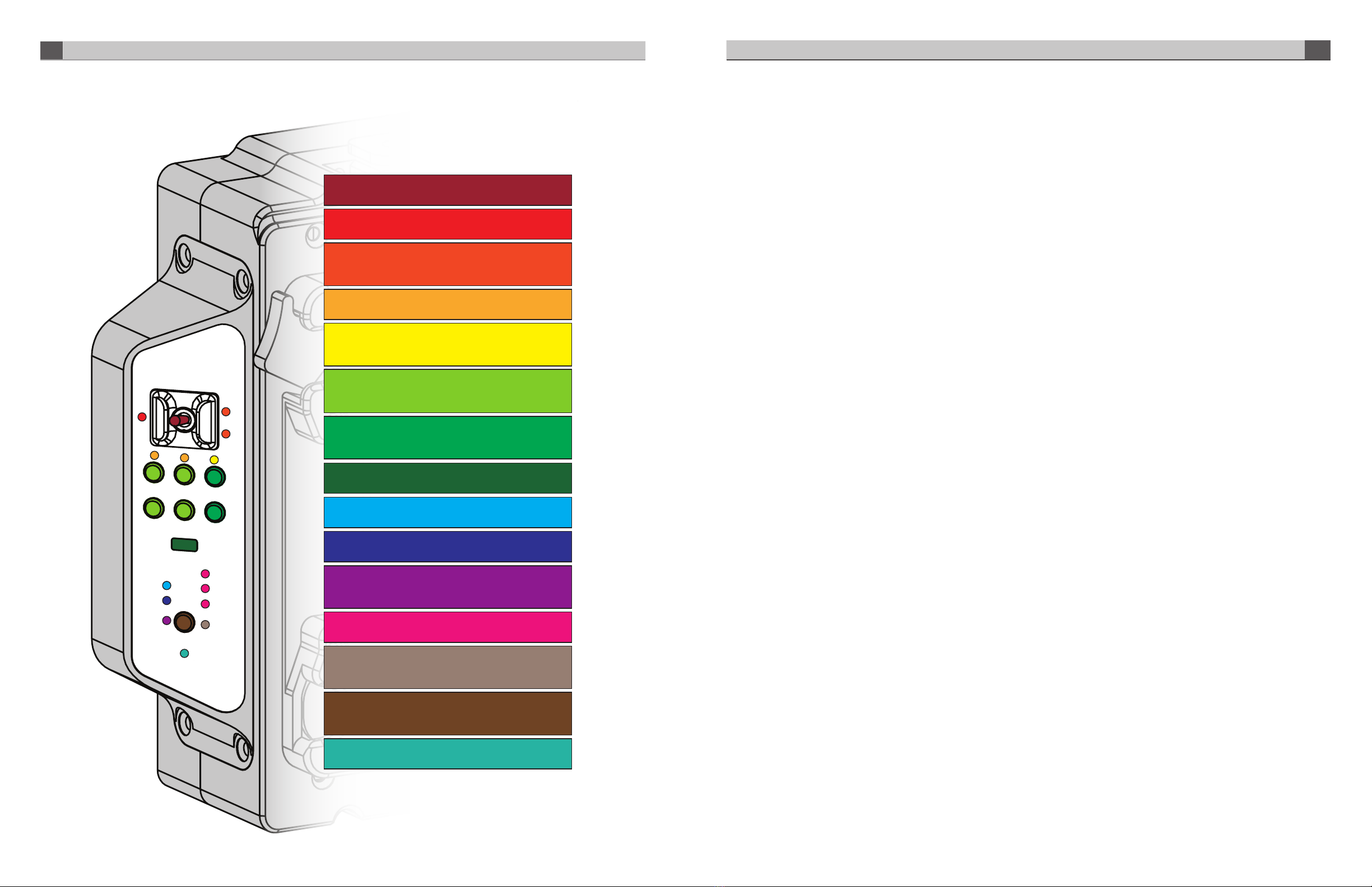
Program Audio Volume Control Buttons:
Controls the volume of the Intercom Program audio out in the
intercom headset.
Intercom Push-To-Talk Switch:
Used to enable talkback on CH 1, CH 2 or CH 1 & 2.
Intercom Talk Active LED Indicator:
Blinks when either CH1 or CH2 is enabled for talkback.
Intercom Channel 1 & 2 Talk Active LED Indicator:
Blinks when the PTT switch has been used to enable
talkback on CH 1 or CH2.
Intercom Channel 1 & 2 Audio Presence LED Indicator:
Illuminates when audio is present.
Program Audio Presence LED Indicator: Illuminates when
audio is present on either of the two Program Audio channels
sent from the Base to the Camera Head units.
Intercom Channel 1 & 2 Audio Volume Control Buttons:
Controls the volume of the Intercom Channel 1 & 2 audio out
in the intercom headset.
Tally Active LED Indicators:
Illuminates Red for PGM Tally, Green for PVW Tally.
Fiber Link Active LED Indicator: Illuminates when there is a
valid fiber connection to the Base Unit.
Camera SDI Video Presence LED Indicator:
Illuminates when the Camera SDI video is present.
Viewfinder Camera Active LED Indicator:
Illuminates when the Camera SDI Video is currently being
routed through to the Viewfinder output.
Return 1, 2, 3 SDI Video Presence LED Indicator: Illuminates
when video is present on the Return 1,2, or 3 video channel.
Viewfinder Return 1 Active LED Indicator:
Illuminates when the Return 1 SDI video is currently being
routed through to the Viewfinder output.
Viewfinder Select Button:
Controls the routing of either the Camera SDI video or the
Return 1 SDI video to the Viewfinder output.
Power LED Indicator:
Illuminates when power is applied to the Camera Head Unit.
VIEW FINDER OPERATION
The Viewfinder button on the Camera Unit’s control panel is used
to select the video source that is output from the Viewfinder BNC
Connector. Pressing this button will change between the Camera’s
video output and the Return 1 video being sent by the base station.
LED’s on the control panel indicate which source is currently switched
to the Viewfinder output.
An external switch connected to the DB-15 GPIO connector on the
Camera Unit may also be used to control the Viewfinder output, please
refer to the pinout guide for pinout information. The Viewfinder select
pin on the GPIO connector is typically used with a momentary type push
button switch. When this pin is connected to Ground, the Viewfinder BNC
will output Return 1 video. When this pin is left open or unconnected,
the Viewfinder BNC will output the Camera’s video signal.
The Viewfinder output can also be selected using the RET button on
the Lens. Note that this requires GY-HM890U camera firmware V0301-
0070, or later, and this option is enabled in the Camera’s menu under:
Camera Function; User Switch Set, Return Video Camera
Return.
INTERCOM OPERATION
The top portion of the Camera Unit’s control panel is used to control
intercom operation of the camera operator’s headset. These controls
consist of: a push-to-talk (PTT) switch, volume control buttons, and
indicator LEDs. There are additional controls located next to the
headset connector for Mic Gain and Sidetone adjustment. Mic Gain and
Sidetone level are adjusted using a small screwdriver.
The intercom headset connector can be used with industry standard
dual-mu or single-mu headsets. Intercom Belt Packs cannot be
plugged into the Camera Unit. When using dual-mu headsets, identical
audio will be present in both ears.
The volume controls allow for a mix of both intercom channels and
program audio all to be listened to in the headset simultaneously. The
LED above each channel’s set of volume control buttons will illuminate
whenever audio is present on that channel. When adjusting the volume,
these LED’s will rapidly blink 3 times whenever the min or max volume
setting has been reached.
The intercom Talkback switch, or PTT switch, provides Momentary/
Latching operation of the headset microphone to allow the operator
to talk on a particular intercom channel, or on both channels
simultaneously.
For Momentary Mode, press and hold the PTT switch up or down
towards the intercom channel you wish to speak on and then speak
into the microphone. The TALK and the selected intercom channel
LED’s will blink and the mic will remain open while the PTT switch is
held. Release the PTT switch when finished talking. The mic will close
and the TALK and channel LED’s will turn o.
Latching Mode can be used for longer-term, hands-free operation. To
talk on channel 1, quickly toggle the PTT switch upwards towards CH1
and release. The mic will latch open and the TALK and CH1 LED’s will
blink continuously. When finished talking, quickly toggle the PTT switch
upwards again and release. The mic will then close and the TALK and
CH1 LED’s will turn o.
To talk on channel 2, quickly toggle the PTT switch downwards towards
CH2 and release. The mic will latch open and the TALK and CH2 LED’s
will blink continuously. When finished talking, quickly toggle the PTT
switch downwards again and release. The mic will close and the TALK
and CH2 LED’s will turn o.
To talk on both channels 1 and 2 simultaneously, first quickly toggle the
PTT switch upwards towards CH1 and release. The mic will latch open
and the TALK and CH1 LED’s will blink continuously. Next, quickly toggle
the PTT switch downwards towards CH2 and release. The mic will stay
open and now the TALK, CH1 and CH2 LED’s will all blink continuously.
When finished talking, quickly toggle the PTT switch upwards and
release to disengage CH1 (the CH1 LED will turn o) then quickly toggle
the PTT switch downwards and release to disengage CH2 (the CH2 LED
will turn o). The mic will close and the TALK, CH1 and CH2 LED’s will
all turn o.
An external switch connected to the DB-15 GPIO connector on the
Camera Unit may also be used to control Intercom Talkback operation,
please refer to the pinout guide for pinout information. Two mic trigger
GPI pins are provided, one for CH1 and one for CH2. A single SPDT
momentary type switch or 2 SPST switches may be used.
Intercom Talkback operation can also be controlled using the REC
button on the Camera’s Lens. Note that this requires GY-HM890U
camera firmware A518-00FB, or later, and this option can be enabled
in the Camera’s menu under: Camera Function >Lens REC >(ICOM2,
ICOM1, REC). Momentary and Latching operation is supported from the
REC button only on the intercom channel that is selected in the menu.
Both channels cannot be activated simultaneously from the REC button.
CAMERA UNIT - CONTROLS & INDICATORS
Instruction Manual, FS-900 SYSTEM DESCRIPTION 8
7CAMERA UNIT - CONTROLS & INDICATORS Instruction Manual, FS-900

BASE UNIT - CONNECTORS & CONTROLS (Rear)
Intercom 2-Wire/4-Wire Selector Switch: Selects between
2-Wire mode or 4-Wire mode
AC Mains Input 1 & 2 Connector: Connector 1 provides power to
the base unit and power to all the cameras. AC Mains 1 is primary AC power
input. AC Mains 2 provides redundant power to ONLY the base station.
OpenGear Option Slot 1 & 2:
For future use.
Camera 1, 2, & 3 Hybrid Fiber-Optic Connector:
Use either SMPTE or Neutrik cable (depending on option ordered) to
connect cameras to base unit. Carries all data between camera head
unit and base unit and provides power to camera head as well.
Program Audio & Intercom DB25 Connector:
Intercom and PGM Audio signals are connected here. See page 16 for
detailed pinout assignments.
Return 1, 2, & 3 SDI Video Input BNC Connector:
Return video input channels to the base which are sent to the three
camera units.
Timecode Input BNC Connector: Timecode input to Base Unit
which is then sent to the three Camera Head Units.
2-Wire Intercom Autonull Switch: Toggling it up performs an
automatic nulling function on intercom CH1. Toggling it down performs
this function on intercom CH2.
Video Reference Input BNC Connector (looping):
Video input reference signal is connected here.
Camera 1 Timecode Output BNC Connector:
Timecode signal sent from Camera 1 thru Camera Head 1 Unit.
Camera 1, 2, & 3 RCP Connector: Remote control panel inputs.
Tally & GPIO DB25 Connector: Connect Tally and GPIO signals for
each camera here. See page 15 for detailed pinout assignments.
Ethernet Connector:
Cameras 1, 2, & 3 10/100/1000 mbps Ethernet port connections.
Camera 1, 2, & 3 SDI Video Output A & B BNC Connector:
SDI video channel from cameras 1, 2, & 3 available at these connectors.
Two copies of each camera’s video output are provided on these BNC’s.
Camera 1 LTC Presence LED Indicator: Illuminates when a valid
timecode signal is being received from Camera 1
Cameras 1, 2, & 3 SDI Video, RCP Data, Fiber Link LED
Indicators: Illuminates when the SDI video, RCP data, and Fiber Link
from Cameras is present.
SDI Return 1, 2, & 3 Video Presence LED Indicator:
Illuminates when the Return video channels input has a valid signal on it.
Intercom Ch1 & Ch2 Audio Presence LED Indicator: Illuminates
when the Intercom Ch1 Audio channel has a valid audio signal on it.
Program Audio Presence LED Indicator: Illuminates
when the Program Audio channel has a valid audio signal on it.
Menu Navigation Button: Controls front panel TFT display.
See Operations Section for description.
TFT Display: See Operations Section for description.
Reference Presence LED Indicator: Illuminates when a valid
Reference Signal is connected to the Base.
Power LED Indicator: Illuminates when the Base Unit has AC
power applied to it.
SDI RET 1
SDI RET 2
SDI RET 3
SDI
RCP
LINK
AUD RET 1
ICOM 1
ICOM 2
REF IN
NAV
POWER
SDI
RCP
LINK
TC
SDI
CAM 1
CAM 2 CAM 3
RCP
LINK
BASE UNIT - CONTROLS & INDICATORS (Front) BASE UNIT POWER
9SYSTEM DESCRIPTION Instruction Manual, FS-900 Instruction Manual, FS-900 BASE UNIT POWER 10
AC1
AC2
48V
48V
48V
Base Unit
Electronics
12V
12V

FS-900 Triple
Studio Camera Interface
ProHD Base Station
APPLICATION & USAGE
ProHD Base Unit
All of the video signals coming from the camera and its accessories (viewfinder, etc.) are fed to the FS-900 Triple Studio Camera
Interface system’s 1 RU base station enclosure via the SMPTE or opticalCON swivel connector which also supplies power.
FS-900 Triple Studio Camera Interface connected to ProHD Base Unit
Fiber Installation and Power vs Distance. Up to 300 meters (1000 feet) on SMPTE 304 Hybrid Fiber
All HD, Video, Audio and control signals, plus up to 100 Watts of continuous 14VDC Power
SIGNAL FLOW - BASE UNIT
11 SYSTEM DESCRIPTION Instruction Manual, FS-900 Instruction Manual, FS-900 SIGNAL FLOW - BASE UNIT 12
FS-900
Camera x3
Return Video
1,2,3
Remote
Control x3
Tally & GPIO
AC Mains Input 1 Connector provides power to the base unit and
power to all the cameras. AC Mains 1 is primary AC power input.
AC Mains Input 2 provides redundant power to ONLY the base unit.
Ethernet x3
Intercom
2-wire/
4-wire
Video
Output x3
Program
Audio & Intercom

SIGNAL FLOW - CAMERA UNIT
48Vdc to 14Vdc48Vdc
(From Base)
Base Unit - Menu Details
Base Fiber Status Menu:
Base Fiber Status
Base A/V Status Menu:
Base Video Status
Base Top Menu:
Base System Status
Home Status Screen:
System Status
Base System Status Menu:
Base System Status
Cam 1 Cam 2 Cam 3
Rx1: -xxdBm -xxdBm -xxdBm
Rx2: -xxdBm -xxdBm -xxdBm
Rx3: -xxdBm -xxdBm -xxdBm
Back Home
Cam 1: SD/HD/3G Ret1: SD/HD/3G
Cam 2: SD/HD/3G Ret2: SD/HD/3G
Cam 3: SD/HD/3G Ret3: SD/HD/3G
Ref: NTSC/PAL/HD
Back Home
Fiber Status
A/V Status
System Status
Back Home
Base: OK
Camera 1: OK
Camera 2: OK
Camera 3: OK
Back Home
Main CPU Rev: ver
Display CPU Rev: ver
FPGA Rev: ver
Back Home
13 SIGNAL FLOW - CAMERA UNIT Instruction Manual, FS-900 Instruction Manual, FS-900 OPERATION 14

Camera 1, 2 & 3 - Menu Details
Home Status Screen:
System Status
Camera Top Menu:
Camera System Status
Camera 1/2/3 Top Menu
Camera 1/2/3 Menu
Base: OK
Camera 1: OK
Camera 2: OK
Camera 3: OK
Back Home
Camera 1: OK
Camera 2: OK
Camera 3: OK
Back Home
Fiber Status:
A/V Status:
System Status:
Power Status:
Back Home
Fiber Status Menu:
Cam 1/2/3 - Fiber Status
A/V Status Menu:
Cam 1/2/3 - Video Status
System Status Menu:
Cam 1/2/3 - System Status
Power Status Menu:
Cam 1 /2/3- Power Status
Rx Power Temp
1 -xxdBm deg C
2 -xxdBm deg C
3 -xxdBm deg C
4 -xxdBm deg C
5 -xxdBm deg C
Back Home
CPU Rev: ver
FPGA Rev: ver
Vin: xx.x V
Power: xx.x W
Back Home
Fiber: xx.x V Cam: xx.x W
Batt: xx.x V FBack: xx.x W
Sys: xx.x V Port 1: xx.x W
Total: xx.x W Port 2: xx.x W
Port 3: xx.x W
Back Home
Cam 1: SD/HD/3G
Ret 1: SD/HD/3G
Ret 2: SD/HD/3G
Ret 3: SD/HD/3G
Ref: NTSC/PAL/HD
Back Home
Detail Connector Pinouts - Base Unit
Base Unit Intercom/Audio Connector Pin-out
Number Description Number Description
1 2-Wire Intercom Pin2 / 4-Wire Intercom Ch1 Output+ 14 2-Wire Intercom Pin3 / 4-Wire Intercom Ch2 Output+
2 4-Wire Intercom Ch1 Output- 15 4-Wire Intercom Ch2 Output-
3 GND 16 GND
4 4-Wire Intercom Ch1 Input+ 17 4-Wire Intercom Ch2 Input+
5 4-Wire Intercom Ch1 Input- 18 4-Wire Intercom Ch2 Input-
6 PGM Audio Ch1 Input+ 19 PGM Audio Ch2 Input+
7 PGM Audio Ch1 Input- 20 PGM Audio Ch2 Input-
8 GND 21 GND
9 GND 22 N/C
10 Intercom MIC Kill GPI Input 23 N/C
11 N/C 24 N/C
12 GND 25 GND
13 GND
Base Unit GPIO Connector Pin-out
Number Description Number Description
1 Camera 1 Program (Red) Tally GPI Input 14 GND
2 Camera 1 Preview (Green) Tally GPI Input 15 GND
3 Camera 1 GPI Input 16 GND
4 Camera 1 GPO Output 17 GND
5 Camera 2 Program (Red) Tally GPI Input 18 GND
6 Camera 2 Preview (Green) Tally GPI Input 19 GND
7 Camera 2 GPI Input 20 GND
8 Camera 2 GPO Output 21 GND
9 Camera 3 Program (Red) Tally GPI Input 22 GND
10 Camera 3 Preview (Green) Tally GPI Input 23 GND
11 Camera 3 GPI Input 24 GND
12 Camera 3 GPO Output 25 GND
13 +12VDC Output
15 OPERATION Instruction Manual, FS-900 Instruction Manual, FS-900 DETAIL CONNECTOR PINOUTS - BASE UNIT 16

Detail Connector Pinouts - Camera Unit
Camera Unit GPIO Connector Pin-out
Number Description Number Description
1 Program (Red) Tally GPO Output 9 GND
2 Preview (Green) Tally GPO Output 10 GND
3 GPO Output 11 Intercom MIC Ch1 PTT GPI Input
4 GPI Input 12 Intercom MIC Ch2 PTT GPI Input
5 Viewfinder Input Select GPI Input 13 N/C
6 GND 14 N/C
7 GND 15 +12VDC Output
8 GND
Camera Unit Audio Connector Pin-out
Number Description Number Description
1 GND 6 PGM Audio Ch1 Output+
2 PGM Audio Ch1 Output- 7 GND
3 PGM Audio Ch2 Output+ 8 PGM Audio Ch2 Output-
4 GND 9 N/C
5 N/C
Camera Unit Intercom Headset Audio Connector Pin-out
Number Description
1 GND
2 MIC Input+
3 GND
4 Audio L Output
5 Audio R Output
Camera Unit Auxiliary Power Output Connector Pin-out
Number Description
1 GND
2 GND
3 +12VDC Output
4 +12VDC Output
SMPTE Hybrid Fiber Cable system power limits
MDCAB01175 - 3' Hirose, 4 AMP accessory power cable wiring diagram
36"
1"
Camera Unit 3’ Hirose Power Cable Pinout
Pin # Function Notes
J1-1 GND White
J1-2 GND White/Blue
J1-3 +14V Out Blue/White, 2A Max
J1-4 +14V Out Blue, 2A Max
36"
1"
Camera Unit 3’ Hirose Power Cable Pinout
Pin # Function Notes
J1-1 GND White
J1-2 GND White/Blue
J1-3 +14V Out Blue/White, 2A Max
J1-4 +14V Out Blue, 2A Max
17 DETAIL CONNECTOR PINOUTS - CAMERA UNIT Instruction Manual, FS-900 Instruction Manual, FS-900 HIROSE CABLE INFORMATION 18

SDI Video
Interface SMPTE ST259, ST292, ST424
Data Rate 270Mbps, 1.5Gbps, 3Gbps
Input/output Level 800mVp-p
Input/output Impedance 75 Ohms
Connector, Camera Unit BNC,
Connector, Base Unit BNC
Embedded Audio Supported Yes
Video Genlock (Reference)
Type Analog Black Burst, Tri-Level
Impedance 75 Ohms
Level 1Vp-p
Connector, Camera Unit Internal 68-pin
Connector, Base Unit BNC
Analog Audio
Type Balanced Analog Line-Level
Level +4dBu nominal, +24dBu max.
Input Impedance > 10k ohms
Output Impedance 50 ohms
THD+N Better than 0.1%
Frequency Response +0.1 dB/-3dB, 20Hz to 20kHz
Connector, Camera Unit DB9
Connector, Base Unit DB25
Intercom Audio
Number of Channels 2
Interface 2-Wire or 4-Wire
Compatibility RTS, Clear-Com
Headset MIC Type Dynamic
Headset MIC Impedance 200 Ohms nominal
Level, 4-Wire +4dBu nominal, +24dBu max.
Level, 2-Wire -10dBu nominal
Connector, Headset XLR-5
Connector, Base Unit DB25
Camera Remote Control
RCP Camera Control
(Remote)
Type JVC RCP (RS232)
Connector, Camera Unit Internal 68-pin
Connector, Base Unit 6 pin Mini-DIN
Ethernet
Ethernet
Data Rates 10/100/1000 Base-T
Connector RJ45 Cat5e
Tally / GPIO
Input type Short to GND or TTL Low to Activate
Output Type Relay Contact Closure (30V, 2A max)
Connector, Camera Unit DB15
Connector, Base Unit DB25
Timecode
Type SMPTE/EBU LTC
Inputs Unbalanced, 15Vp-p max
Outputs Unbalanced, 3Vp-p max
Connector, Camera Unit Internal
Connector, Base Unit BNC
Electro-Optical
Operating Wavelengths 1471-1611nm
TX Laser Output Power 0dBm (Class 1 Laser)
Receiver Sensitivity -20dBm
Fiber Compatibility Single-mode
Optical Connector Types opticalCON DUO, SMPTE 304M
Power Supply
Power Input, Base IEC320, Universal Input, 90-250VAC, 50-60Hz
Power Input, Camera:
Remote Power Hybrid Fiber Connector, 54 VDC
Local Power Battery Mount (Anton Bauer or V-Mount), 11-17
VDC
Environmental
Operating Temperature 0 to 50°C
Operating Temperature 0 to 95% RH, non-condensing.
Technical Specifications
FS-900 Triple Studio Camera Interface System is manufactured, warranted and supported by MultiDyne Video and Fiber Optic Systems, and
distributed in North America by JVCKENWOOD USA Corporation. It has two years warranty for Parts and Labor from date of invoice.
Please review additional warranty terms at www.multidyne.com located in terms of sale. A hard copy will be provided promptly and free of
charge upon request.
To obtain service or for further information, please contact:
MultiDyne Electronics Inc.,
10 Newton Place,
Hauppauge, NY 11788
Toll free: 877-685-8439
Tel: 516-671-7278
Website: www.multidyne.com
EU JVC Service Contacts
Importer (EU only)
JVCKENWOOD U.K. Limited
12 Priestley Way, London NW2 7BA, UNITED KINGDOM
Importeur (Nur EU)
JVCKENWOOD Deutschland GmbH
Konrad-Adenauer-Allee 1-11, 61118 Bad Vilbel, DEUTSCHLAND
Importatore (Solo EU)
JVCKENWOOD Italia S.p.A.
Via G. Sirtori 7/9, 20129 Milano, ITALIA
Importeur (Alleen EU)
JVCKENWOOD Belgium N.V.
Leuvensesteenweg 248J, 1800 Vilvoorde, BELGIQUE
Importeur (Alleen EU)
JVCKENWOOD Europe B.V.
Amsterdamseweg 37, 1422 AC Uithoorn, NEDERLAND
Importateur (UE uniquement)
JVCKENWOOD Europe B.V. Succursale France
7 Allée des Barbanniers CS10033 92632 GENNEVILLIERS CEDEX
FS-900 Triple Studio Camera Interface System is manufactured, warranted and supported by MultiDyne Video and Fiber
Optic Systems, and distributed in North America by JVCKENWOOD USA Corporation. It has two years warranty for Parts and
Labor from date of invoice.
Limited Warranty
19 TECHNICAL SPECIFICATIONS Instruction Manual, FS-900 Instruction Manual, FS-900 LIMITED WARRANTY 20
Other manuals for FS-900
1
Table of contents
Other JVC Camera Accessories manuals

JVC
JVC CU-PC1 SU User manual

JVC
JVC KA-DV350U User manual

JVC
JVC DPT 115 User manual

JVC
JVC KY-F560U - 3-ccd Color Camera User manual

JVC
JVC VF-HP900G User manual

JVC
JVC CU-PC1 SU User manual

JVC
JVC GY-HD250U - 3-ccd Prohd Camcorder Dimensional drawing

JVC
JVC GY-HM750U User manual

JVC
JVC LYT2232-002A User manual

JVC
JVC CamiFlex FG-CAM-F4/U User manual