Condair HSC User manual

Raumhygrostat HSC
HSC room humidistat
Hygrostat ambiant HSC
Installationsanleitung
Installation Instructions
Instructions d’installation
2535448 DE/EN/FR 1405
Allgemein
DerRaumhygrostatHSCdientzurEin/Aus-Rege-
lungdes Condair CP3, des Condair CP3mini, des
CondairEL2,desCondairABS3unddesDefensor
Mk5. Diese Installationsanleitung beschreibt den
Anschluss des Raumhygrostaten HSC an diese
Geräte sowie die Konguration der Geräte für den
Betrieb mit dem Raumhygrostat HSC.
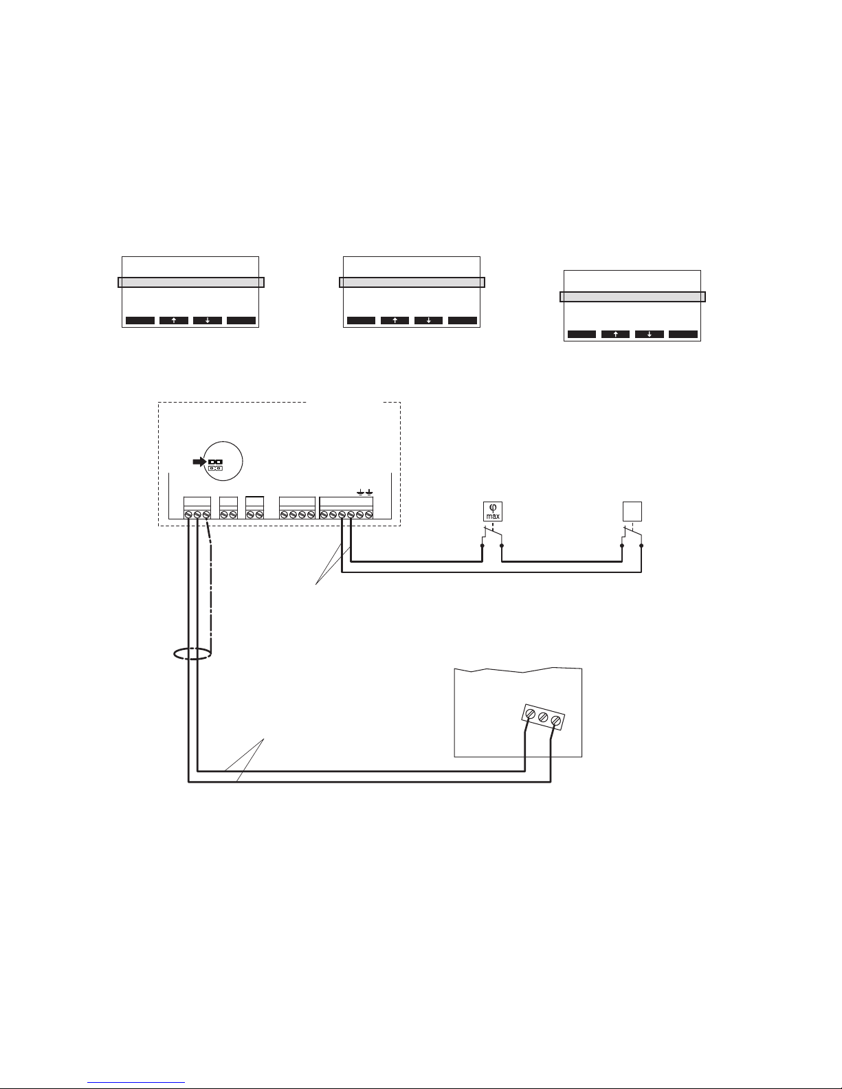
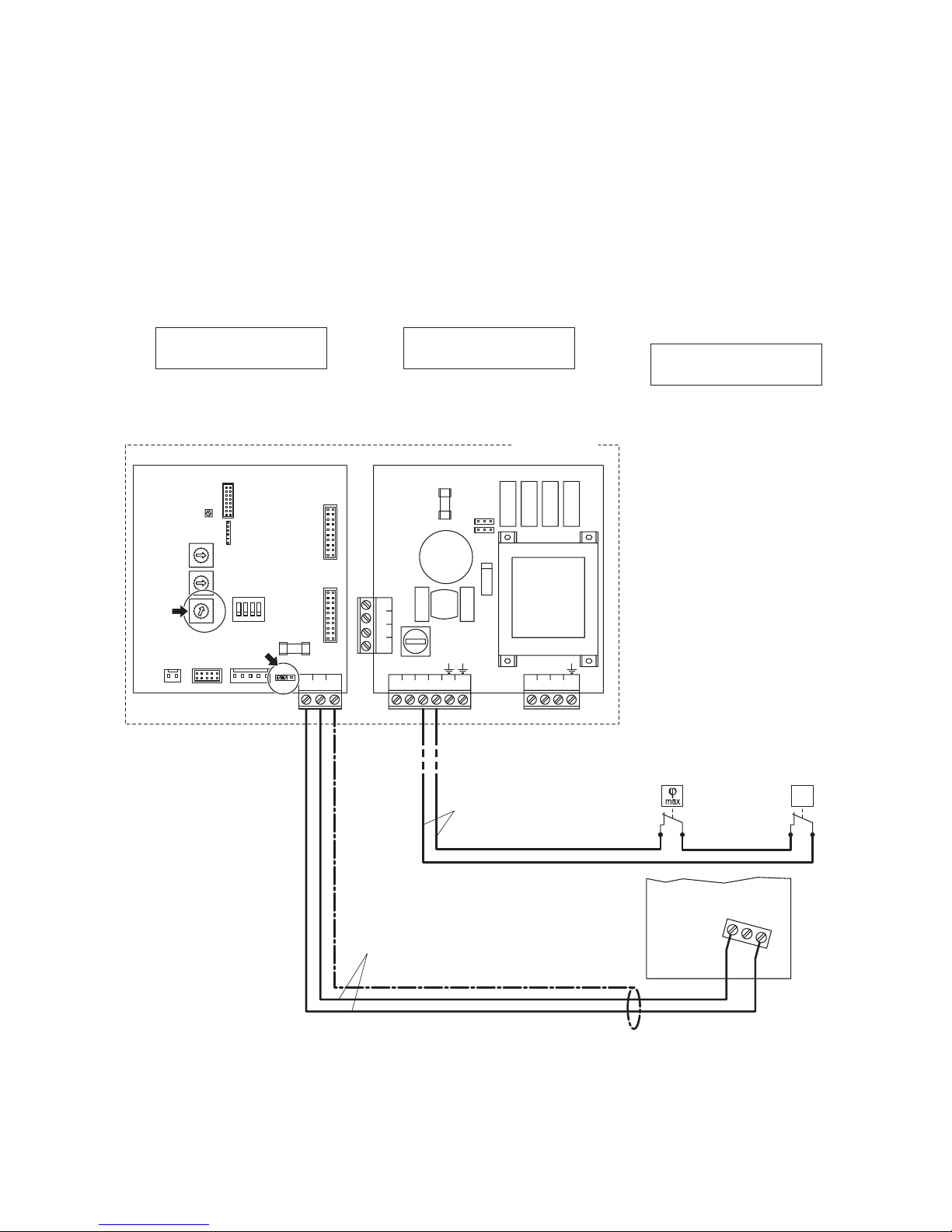
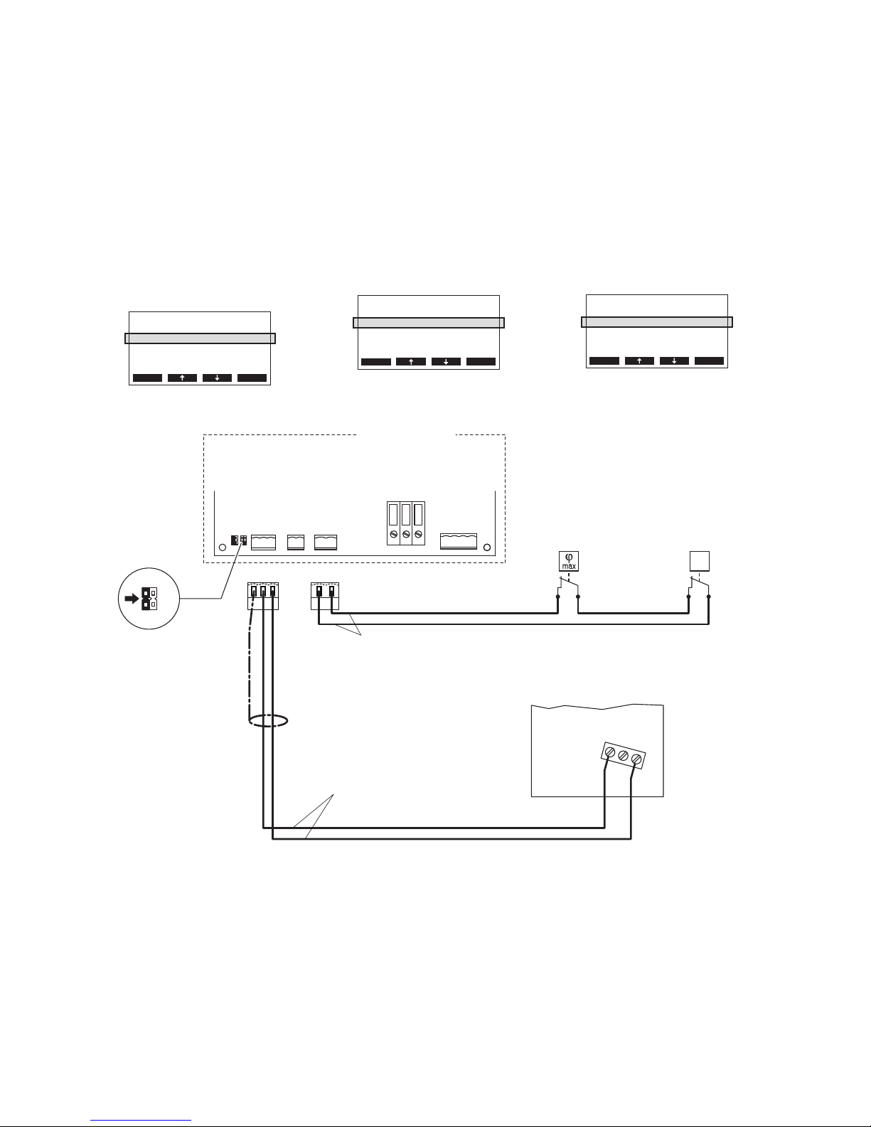
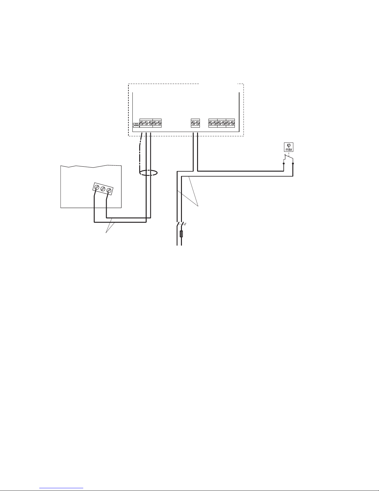
Hinweis: Zur Gewährleistung der Betriebssicher-
heit ist der Betrieb der Befeuchter mit einem
Feuchtewächter (z.B. Kanalhygrostat HBC oder
RaumhygrostatHSC)undeinemStrömungswäch-
ter zu überwachen. Diese Überwachungsgeräte
sindandieexterneSicherheitskettedesjeweiligen
Geräts anzuschliessen (Achtung! Die Kontakte
müssen potenzialfrei sein!).
Diese Installationsanleitung ist eine Ergänzung
zur Installationsanleitung zum Raumhygrostat
HSC und den Elektroinstallationsanleitungen zu
den entsprechenden Geräten. Die Hinweise in
diesen Dokumenten müssen zwingend beachtet
und eingehalten werden.
Sicherheit
Beachten Sie bitte alle lokalen Vorschriften
betreffend die Ausführung von elek trischen In-
stallationen.
Die Installationsarbeiten dürfen nur durch aus-
gewiesenes Fachpersonal (Elektriker oder
Fachkraft mit gleichwertiger Ausbildung)
durchgeführt werden.
Achtung Stromschlaggefahr! Vor Beginn der
Installationsarbeiten ist das Gerät, an das der
RaumhygrostatHSCangeschlossen werden soll,
vom Strom netz zu trennen. Der Wiederanschluss
an das Stromnetz darf erst nach Fertigstellung
sämtlicher Installationsarbeiten erfolgen.
Achtung! Die elektronischen Bauteile im Innern
des Raumhygrostaten HSC und der Befeuchter
sind sehr empndlich gegen elektro statische
Entladungen. Zum Schutz dieser Bauteile müssen
für alle Installationsarbeiten Massnahmen gegen
Beschädigung durch elektrostatische Entladung
(ESD–Schutz) getroffen werden.
General
The HSC room humidistat is to be used for On/Off
regulation of the Condair CP3, Condair CP3mini,
Condair EL2, Condair ABS3 and the Defensor
Mk5.ThecurrentInstallationInstructionsdescribe
theconnectionoftheHSC room humidistat tothese
units as well as their conguration required for
operation with the HSC room humidistat.
Note: For safety reasons the operation of the
humidiers must be monitored by a humidity
monitor (e.g. HBC duct humidistat or HSC room
humidistat) and a ow sensor. These monitoring
devices must be connected to the external safety
chain of the corresponding unit (Caution! The
contacts must be potential-free).
These Installation Instructions are a complement
to the Installation Instructions of the HSC room
humidistat and the Electrical Installation Instruc-
tions of the respective units. It is mandatory to
observe and to follow the instructions provided
in these documents.
Safety
Please observe all local regulations concerning
the electric installation.
The installation work must be performed only by
adequately qualied personnel (electrician or
workman with equivalent training).
Warning - danger of electric shock! Before
starting the installation work the unit to which the
HSC room humidistat will be connected must be
disconnected from the mains and may be recon-
nected to mains only after all installation work
has been completed.
Warning! The electronic components inside the
HSC room humidistat and the humidiers are
very susceptible to electrostatic discharges. For
the protection of these components, measures
must be taken during all installation work to pre-
vent damage caused by electrostatic discharge
(ESD–protection).
Généralités
L’hygrostat ambiant HSC est destinée pour la
régulationtout-ou-rienduCondairCP3, du Condair
CP3 mini, du Condair EL2, du Condair ABS3
et du Defensor Mk5. Les présentes instruc-
tions d’installation décrivent le raccorde ment de
l’hygrostat ambiant HSC à ces appareils et leur
conguration requise pour l’exploitation avec
l’hygrostat ambiant HSC.
Nota: pour des raisons de sécurité, l’opération
des humidicateurs doit être surveillée par un
contrôleur d’humidité (p.ex. l’hygrostat pour gaine
HBCoul’hygrostat ambiant HSC) et un contrôleur
de ux d’air. Ces dispositifs de surveillance doivent
être raccordés à la chaîne de sécurité externe de
l’unitéconcernée(Attention!Les contacts doivent
être sans potentiel).
Les présentes instructions d’installation sont un
complément des instructions d’installation concer-
nant l’hygrostat ambiant HSC et des instructions
d’installation électrique des appareils respectifs.
Les consignes gurant dans ces documents sont
à observer et à respecter impérativement.
Sécurité
Veuillez observer chaque prescription locale
concernent l’exécution d’installations élec-
triques.
Seules les personnes spécialisées compé-
tentes (électricien ou spécialiste de même
formation) sont autorisées à effectuer les travaux
d’installation.
Attention, risque de choc électrique! Avant de
commencer des travaux d’installation, séparer du
réseau électrique l’appareil destiné à être raccordé
à l’hygrostat ambiant HSC. N’effectuer le raccor-
dement de l’humidicateur au réseau électrique
qu’au terme de tous les travaux d’installation.
Attention! Les composants électroniques in-
tégrés dans l’hygrostat ambiant HSC et les
humidicateurs sont très sensibles aux décharges
électrostatiques. Ces composants impliquent,
lors de tous les travaux d’installation, la prise des
mesures de précaution contre leur détérioration
par décharge électrostatique.

Anschluss des HSC am Condair CP3
1. Den HSC über ein abgeschirmtes, zweiadriges
Kabel (Aderquerschnitt maximal 0.5 mm2)
gemäss dem untenstehenden Schema an die
entsprechenden Klem men auf dem Leistungs-
print des Gerätemoduls A anschliessen.
2. Jumper “JP3” auf dem Leistungsprint des Ge-
rätemoduls A auf Position “24 V” stecken.
3. Den Condair CP3 in Betrieb nehmen und in
der Einstellebene der Gerätesoftware den
Parameter “Regelung” auf “24OnOff” ein-
stellen(sieheMontage-undBetriebsanleitung
zum Condair CP3).
Connecting the HSC to the Condair CP3
1. Usea shielded two-wire cable (maximumwire
section 0,5 mm2) to connect the HSC to the
appropriate terminals located on the power
board of unit module A (see wiring diagram
below).
2. Set the jumper “JP3” on the power board of
unit module A to position “24 V”.
3. Set the Condair CP3 into operation, go to
the setup level of the software and set the
parameter “Hum.Control” to “24OnOff”
(refer to the Condair CP3 installation and
operating instructions).
Raccordement du HSC au Condair CP3
1. Au moyen d’un câble blindé à deux brins
(secteur maximum de l’âme: 0.5 mm2),
brancher le HSC selon le schéma électrique
ci-dessous aux bornes correspondantes de la
platine de puissance du module d’appareil A.
2. A la platine de puissance du module d’appa-
reil A, encher le cavalier “JP3” sur position
“24 V”.
3. Mettre en service le Condair CP3, accéder au
plan de réglage du logiciel et régler le para-
mètre “Rég.hygromèt” sur “24OnOff” (voir
les instructions d’installation et d’exploitation
concernant le Condair CP3).
Regeleinst.
Regelung :24OnO
Sollwert :Set
Begrenzer :Aus
SignalQuelle:Analog
Esc Set
Entr.Consig.
Rég.hygromèt:24VOnO
PointConsign:Set
Limiteur :O
SourceSignal:Analog
Esc Set
Controls
Hum.Control :24VOnO
Hum.Setpoint:Set
Lim. Control:O
SignalSource:Analog
Esc Set
Sicherheitskette
Safety circuit
Chaîne de sécurité
min. Querschnitt pro Litze 1 mm2
min. cross section per wire 1 mm2
Section min. par fil 1 mm2
∆p
Strömungswächter
Air flow monitor
Contôleur flux d’air
200-240 V / 50...60 Hz
max. Querschnitt pro Litze 0.5 mm2
max. cross section per wire 0.5 mm2
Section max. par fil 0.5 mm2
HSC
12
3
V+ INGND
CONT.SIGN
INGND
LIM. SIGN
L1 NSC1
MAIN SUPPLY
X1
SC2
Condair CP3
Leistungsprint Module A
Power board Module A
Platine de puissance Module A
OUT 24V
JP3
OUT 5V Feuchtewächter
Humidity monitor
Contrôleur d'humidité

Anschluss des HSC am Defensor Mk5
1. HSC über ein zweiadriges Kabel (Ver wendung
eines abgeschirmten Kabels empfohlen,
Aderquerschnitt max. 0.5 mm2) gemäss dem
untenstehenden Schema an die entspre-
chenden Klem men auf dem Steuerprint des
Defensor Mk5 anschliessen.
2. Auf dem Steuerprint des Mk5 Jumper “JP2” auf
Position “24 V” stecken und den Drehschalter
“S3” (Regelsignal) auf Position “1” stellen
(On/Off 24 V).
3. Defensor Mk5 in Betrieb nehmen und in der
Einstellebene der Gerätesoftware die interne
Regelfunktion deaktivieren (siehe Montage-
und Betriebsanleitung zum Defensor Mk5).
Connecting the HSC to the Defensor Mk5
1. Use a two-wire cable (the use of a shielded
cableisrecommended,maximumwiresection
0,5mm2) to connect the HSC to the appropriate
terminals located on the control board of the
Defensor Mk5 (see wiring diagram below).
2. Set the jumper “JP2” of the Mk5 control board
to position “24 V”, then set the “S3” rotary
switch (control signal) to position “1” (On/Off
24 V).
3. Set the Defensor Mk5 into operation, go to
the setup level of the software and disable
the internal controller function (refer to the
Defensor Mk5 installation and operating
instructions).
Raccordement du HSC au Defensor Mk5
1. Au moyen d’un câble à deux brins (l’utilisa-
tion d’un câble blindé recommandé, section
maximum de l’âme, 0.5 mm2), brancher le
HSC selon le schéma électrique ci-dessous
aux bornes correspondantes de la platine de
commande du Defensor Mk5.
2. A la platine de commande du Mk5, encher
le cavalier “JP2” sur position “24 V” et posi-
tionner le commutateur rotatif “S3” (signal de
régulation) sur “1” (On/Off 24 V).
3. Mettre en service le Defensor Mk5 accéder
au plan de réglage du logiciel et désactiver la
fonction de régulation interne (voir les instruc-
tions d’installation et d’exploitationconcernant
le Defensor Mk5).
Reglerfunktion
aus
controller funct
off fonct. du regl.
hors
∆p
F1 (6.3AT)
L1
X1 X6
N SK1SK2
F2 (1AF)
PN P1
JP1
JP2
Speisungsmodul Gerät A
Supply module unit A
Module d’alimentation appareil A
HSC
Defensor Mk5
F5
(200mAF)
1
ON
S4
S1
S2
S3
5V
JP2
V+
423
GNDIN
24V
J3
J6
Com-Port
0
1
2
3
4
5
6
7
8
F
E
D
C
B
A
9
0
1
2
3
4
5
6
7
8
F
E
D
C
B
A
9
0
1
2
3
4
5
6
7
8
F
E
D
C
B
A
9
Steuerprint Gerät A
Control board unit A
Platine de commande appareil A
200-240 V / 50...60 Hz
Sicherheitskette
Safety circuit
Chaîne de sécurité
min. Querschnitt pro Litze 1 mm2
min. cross section per wire 1 mm2
Section min. par fil 1 mm2
Strömungswächter
Air flow monitor
Contôleur flux d’air
max. Querschnitt pro Litze 0.5 mm2
max. cross section per wire 0.5 mm2
Section max. par fil 0.5 mm2
12
3
Feuchtewächter
Humidity monitor
Contrôleur d'humidité

Anschluss des HSC
am Condair CP3 mini
1. Den HSC über ein abgeschirmtes, zweiadriges
Kabel (Aderquerschnitt maximal 0.5 mm2)
gemäss dem untenstehenden Schema an
die entsprechenden Klem men auf dem Leis-
tungsprint des Gerätes anschliessen.
2. Auf dem Leistungsprint des Condair CP3
mini einen Jumper auf JP2-24 V stecken
und den Jumper auf JP1-5V (falls vorhanden)
entfernen.
3. Den Condair CP3 mini in Betrieb nehmen und
in der Einstellebene der Gerätesoftware den
Parameter “Regelung” auf “24OnOff” ein-
stellen(sieheMontage-undBetriebsanleitung
zum Condair CP3 mini).
Connecting the HSC
to the Condair CP3 mini
1. Use a shielded two-wire cable (maximum
wire section 0,5 mm2) to connect the HSC
to the appropriate terminals located on the
power board of the unit (see wiring diagram
below).
2. On the power board of the Condair CP3: set a
Jumper on JP2-24V and remove the Jumper
on JP1-5V (if a jumper is set).
3. Set the Condair CP3 mini into operation, go
to the setup level of the software and set the
parameter “Hum.Control” to “24OnOff”
(refer to the Condair CP3 mini installation
and operating instructions).
Raccordement du HSC
au Condair CP3 mini
1. Au moyen d’un câble blindé à deux brins (sec-
teur maximum de l’âme: 0.5 mm2), brancher
le HSC selon le schéma électrique ci-dessous
aux bornes correspondantes de la platine de
puissance de l’appareil.
2. Ala paltine de puissance du Condair CP3 mini:
installer un cavalier sur JP2-24 V et enlever
le cavalier de JP2-5V (si présent).
3. Mettre en service le Condair CP3 mini, accéder
au plan de réglage du logiciel et régler le para-
mètre “Rég.hygromèt” sur “24OnOff” (voir
les instructions d’installation et d’exploitation
concernant le Condair CP3 mini).
Regeleinst.
Regelung :24OnO
Sollwert :Set
Begrenzer :Aus
SignalQuelle:Analog
Esc Set
Entr.Consig.
Rég.hygromèt:24VOnO
PointConsign:Set
Limiteur :O
SourceSignal:Analog
Esc Set
Controls
Hum.Control :24VOnO
Hum.Setpoint:Set
Lim. Control:O
SignalSource:Analog
Esc Set
CONT.SIGN
V+
GNDCTRL
Sicherheitskette
Safety circuit
Chaîne de sécurité
min. Querschnitt pro Litze 1 mm2
min. cross section per wire 1 mm2
Section min. par fil 1 mm2
∆p
Strömungswächter
Air flow monitor
Contôleur flux d’air
X1 X4 X6
CTRL V+
1 21 21 2 3
GND
BASIC
0-10V
On/Off
24V
5V
PRO
JP4
JP3
JP2
JP1
LIMGND SC1SC2
SAFETY
SC1SC2
24V
5V
JP2
JP1
200-240 V / 50...60 Hz
max. Querschnitt pro Litze 0.5 mm2
max. cross section per wire 0.5 mm2
Section max. par fil 0.5 mm2
Condair CP3 mini
Leistungsprint
Power board
Platine de puissance
PWR
MAIN SUPPLY
X9
LN PE
X8
NL SW N SWL
HSC
12
3
Feuchtewächter
Humidity monitor
Contrôleur d'humidité

Anschluss des HSC am Condair EL2
1. Den HSC über ein abgeschirmtes, zweiadriges
Kabel (Aderquerschnitt maximal 0.5 mm2)
gemäss dem untenstehenden Schema an
die entsprechenden Klem men auf dem Leis-
tungsprint des Gerätes anschliessen.
2. Auf dem Leistungsprint des Condair EL2 einen
Jumper auf JP1 stecken.
Connecting the HSC to the Condair EL2
1. Use a shielded two-wire cable (maximum
wire section 0,5 mm2) to connect the HSC
to the appropriate terminals located on the
power board of the unit (see wiring diagram
below).
2. On the power board of the Condair EL2: set
a Jumper on JP1.
Raccordement du HSC au Condair EL2
1. Au moyen d’un câble blindé à deux brins (sec-
teur maximum de l’âme: 0.5 mm2), brancher
le HSC selon le schéma électrique ci-dessous
aux bornes correspondantes de la platine de
puissance de l’appareil.
2. A la paltine de puissance du Condair EL2:
installer un cavalier sur JP1.
CONT.SIGN
V+ IN GND
X2 X3
VD
MAIN SUPPLY
L1 NSC1SC2
X1
On/Off Mode
JP1
Sicherheitskette
Safety circuit
Chaîne de sécurité
min. Querschnitt pro Litze 1 mm2
min. cross section per wire 1 mm2
Section min. par fil 1 mm2
∆p
Strömungswächter
Air flow monitor
Contôleur flux d’air
200-240 V / 50...60 Hz
max. Querschnitt pro Litze 0.5 mm2
max. cross section per wire 0.5 mm2
Section max. par fil 0.5 mm2
Condair EL2
Leistungsprint
Power board
Platine de puissance
HSC
12
3
Feuchtewächter
Humidity monitor
Contrôleur d'humidité

Anschluss des HSC am Condair ABS3
Den HSC über ein abgeschirmtes, zweiadri-
ges Kabel (Aderquerschnitt maximal 0.5 mm2)
gemäss dem untenstehenden Schema an die
entsprechenden Klem men auf dem Steuerprint
des Gerätes anschliessen.
Connecting the HSC to the Condair ABS3
Use a shielded two-wire cable (maximum wire
section 0,5 mm2) to connect the HSC to the ap-
propriate terminals located on the control board
of the unit (see wiring diagram below).
Raccordement du HSC au Condair ABS3
Au moyen d’un câble blindé à deux brins (secteur
maximum de l’âme: 0.5 mm2), brancher le HSC
selon le schéma électrique ci-dessous aux bornes
correspondantes de la platine de commande de
l’appareil.
Sicherheitskette
Safety circuit
Chaîne de sécurité
min. Querschnitt pro Litze 1.0 mm2
min. cross section per wire 1.0 mm2
Section min. par fil 1.0 mm2
K1N L1 K2 K3
24V LEVELGND IN
NTC
F2
Q2
115 V / 50/60Hz
230 V / 50/60Hz
Condair ABS3
Steuerprint
Control board
Platine de commande
max. Querschnitt pro Litze 0.5 mm2
max. cross section per wire 0.5 mm2
Section max. par fil 0.5 mm2
HSC
12
3
Feuchtewächter
Humidity monitor
Contrôleur d'humidité

© Condair Ltd., Printed in Switzerland
Technische Änderungen vorbehalten
Technical data subject to modification
Sous réserve de modifications techniques

CONSULTING, SALES AND SERVICE:
Manufacturer
:
Condair Ltd.
Talstrasse 35-37, 8808 Pfäffikon, Switzerland
Ph. +41 55 416 61 11, Fax +41 55 416 62 62
info@condair.com, www.condair.com
Reg.No. 40002-2
Other Condair Thermostat manuals
Popular Thermostat manuals by other brands

Siemens
Siemens RDG100T operating instructions

Pro 1 IAQ
Pro 1 IAQ T855i quick start guide

Fantini Cosmi
Fantini Cosmi CH180WIFI Instructions for use

Fantini Cosmi
Fantini Cosmi Intellicomfort+ CH180RF manual

Thermo Sphere
Thermo Sphere BT21 Installation and user guide

Tecnocontrol
Tecnocontrol Easy 503 PROGRAMMING INSTRUCTIONS AND INSTALLATION GUIDE

Solaire
Solaire TITANE ST-PP3 user manual

Isotherm
Isotherm 3000 operating instructions

Pro 1 IAQ
Pro 1 IAQ True Comfort T715 operating manual

Fantini Cosmi
Fantini Cosmi CH180T3K5 Instructions for use

Pro 1 IAQ
Pro 1 IAQ TopTech TT-S-955 installation manual

Pro 1 IAQ
Pro 1 IAQ True Comfort T955WH operating manual