Condair MN Series User manual

SERVICE MANUAL
Condair HumiLife - The flexible room solution
Condair MN
2600434-H EN UL 2206
Humidication and Evaporative Cooling
FOR INTERNAL USE ONLY!

Contact
Condair Ltd.
2740 Fenton Road, Ottawa, Ontario K1T3T7
TEL: 1.866.667.8321, FAX: 613.822.7964
EMAIL: na.humilife@condair.com, WEBSITE: www.condairhumilife.com
Proprietary Notice
This document and the information disclosed herein are proprietary data of Condair Ltd. Neither this document, nor
the information contained herein shall be reproduced, used, or disclosed to others without the written authorization
of Condair Ltd., except to the extent required for installation or maintenance of recipient's equipment.
Liability Notice
Condair Ltd. does not accept any liability due to incorrect installation or operation of the equipment or due to the
use of parts/components/equipment that are not authorized by Condair Ltd.
Copyright Notice
© Condair Ltd., All rights reserved.
Technical modications reserved

3Table of Contents
Table of Contents
1 Introduction 5
2 For your safety 6
3 Commissioning 8
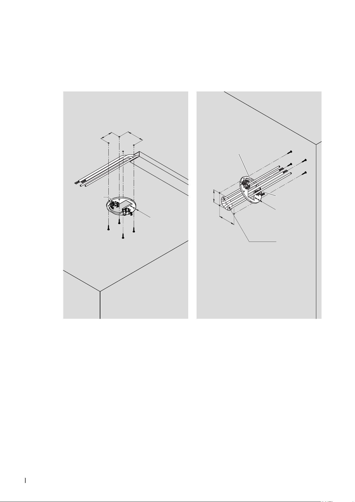
3.1 Installation of humidier units (ush-mounting) 8
3.2 Assembly and connection of the drain module (only with peripheral drainage) 14
3.3 Install water lter(s) and connect water hoses 17
3.4 Connection of the spray loop hoses to the central unit 19
3.5 Perform pressure test on the water system 19
3.6 Connecting the CAN bus cables to the central unit 20
3.7 Connection of the optional RO-HB reverse osmosis unit 24
3.8 Flush the water feed line and connect to the central unit 26
3.9 Connect the control cable(s) of the booster module in the central unit(s) 27
3.10 Connect the reverse osmosis system Condair RO-HB to the power supply 29
3.11 Connect the LAN cable to the central unit 29
3.12 Connect the central unit to the mains with the mains plug 29
3.13 Commissioning and transfer 29
3.13.1 Update of the control software before commissioning 29
3.13.2 Commission the system with the MN service application 29
3.13.3 Connect the gateway 35
3.13.4 User app 39
3.13.5 Transfer of the system 39
4 Service and replacement of components 40
4.1 Notes on servicing the Condair MN / service intervals 40
4.1.1 Taking water samples 41
4.1.2 Replacing UV lamp and check/clean quartz glass 43
4.1.3 Replacing the lter cartridge of the microlter 46
4.1.4 Replace water lter(s) 47
4.1.5 Disinfect water system 48
4.1.5.1 Depressurize the water system 48
4.1.5.2 Disinfect the water system of the Condair MN 51
4.1.5.3 Disinfect the Condair RO-HB reverse osmosis system 61
4.1.5.4 Put the system into operation 71
4.1.6 Check the air pressure of the ow tank of the Condair RO-HB reverse osmosis system 71
4.2 Reset the maintenance counter 72
4.3 Replacement of components 73
4.3.1 Preparing the system for component replacement 73
4.3.2 Resetting the system to normal operating mode after replacing components 73
4.3.3 Replacing the water sensor modules 74
4.3.4 Replacing the drain modules 75
4.3.5 Replacing the valve block 76
4.3.6 Replacing the inlet valve 77
4.3.7 Replacing the control box 78

4Table of Contents
4.3.8 Replacing the humidier unit 81
4.3.9 Replacing the humidier unit's humidity sensor 82
4.4 Updating the control software 83
5 Malfunctions 85
5.1 Fault messages 85
5.2 Water system 86
5.3 Hydraulic 87
5.4 Water quality 87
5.5 Electronics 89
5.6 Re-commissioning process of the Condair MN after error message
"Last ush XX too long ago" (last ush more than 48 hours ago) 92
5.6.1 Fault messages "Last ush XX too long ago" 92
5.6.2 Possible causes of the fault messages "Last ush XX too long ago" 93
5.6.3 States and measures 93
6 Appendix 94
6.1 Flushing section determination 94
6.2 Tools, kits, software and materials needed for commissioning and service 95

5Introduction
1 Introduction
This service manual is intended for trained Condair service technician who has a good knowledge of
the Condair MN, who knows the installation manual and the operation manual, and who is familiar the
hazards associated with handling the device.
If the Condair MN system is operated with the optional reverse osmosis system Condair RO-HB, the
english version of the installation and operation manual of the reverse osmosis system Condair RO-
HB can be downloaded using the following QR code:
Symbols
CAUTION!
The signal word "CAUTION", appearing in combination with the hazard symbol in a circle, indicates
information given in this service manual which, if ignored, could lead to damage and/or the malfunc-
tioning of the device or other material assets.
WARNING!
The signal word "WARNING", appearing in combination with the general hazard symbol, indicates safety
and hazard information given in this service manual which, if ignored, could lead to personal injury.
DANGER!
The signal word "DANGER", appearing in combination with the general hazard symbol, indicates safety
and hazard information in this service manual, which, if ignored, could result in serious personal
injury, including death.

6For your safety
2 For your safety
General
The service technicians assigned to working on the Condair MN must have read and
understood this service manual as well as the installation instructions and the operating
instructions of the Condair MN before starting work on the unit.
An understanding of the contents of the service manual as well as the installation and
operating instructions is a basic prerequisite for protecting personnel from danger, avoid-
ing improper operation and thus for the safe and proper operation of the Condair MN.
Personnel qualications
All work described in this Service Manual must be performed only by trained Condair
service technicians.
It is assumed that the service technicians are familiar with and will abide by the regula-
tions on occupational health and safety and accident prevention.
Hazards that may arise from the Condair MN:
DANGER!
Risk of electrocution
The Condair MN's central unit runs on mains power. If the central unit is open,
live parts may be touched. Touching live parts may cause severe injury or death.
For this reason: Before starting work on the central unit, disconnect it from the
mains power supply (remove plug from socket).
Warning!
System contamination hazard
If the Condair MN is switched off, there is a risk of the water supply line and
the internal water system becoming contaminated, as the water system is then
not being ushed regularly.
For this reason: The Condair MN must not be switched off after being commis-
sioned. This will ensure that the water system is purged at regular intervals,
and any contamination is counteracted.

7For your safety
Warning!
UV-C radiation
A UV lamp is built into the Condair MN's central unit. In principle this should
pose no risks, as it is installed in a radiation-proof housing. If the UV lamp is
operated outside of this housing, harmful UV-C radiation may be released. This
may cause damage to the eyes and skin.
For this reason: the UV lamp must never be operated outside of the protec-
tive housing. The central unit must be switched off and disconnected from the
mains power supply (remove the plug from the socket) before the central unit
is opened.
Warning!
Waste from damaged UV lamps may lead to injury and cause damage to human
health and harm to the environment.
For this reason: the waste from damaged UV lamps must be disposed of in
accordance with local provisions on hazardous substances and the site of the
damage must be cleaned properly.
CAUTION!
Leaky or defective water pipes/connections may lead to water damage.
For this reason: After replacing components, make sure the system is tight.

8Commissioning
3 Commissioning
3.1 Installation of humidier units (ush-mounting)
The installation of humidier units described below assumes that the preliminary installation work has
been completed, that the appropriate holes have been drilled at the ceiling or wall junction points of the
humidier units, and that the hoses and CAN bus cables have been retracted.
The humidier units are to be mounted as follows.
1a. Mount the installation ring (for ush mounting without catch springs only):
• Using two screws, mount the installation ring at the intended position in such a way that it is
concentric with the hole on the ceiling or wall. Make sure to use screws that are suitable for
mounting on the respective surface.
Important: If mounting on the ceiling, the installation ring must be mounted in such a way
that the recess for the Humstick in the installation ring points towards the middle of the
room. If mounting on a wall, the installation ring must be mounted in such a way that the
designation "UP" in the mounting ring points upwards!
ø2.95" ±0.04"
(ø75 mm ±1 mm)
ø2.95" ±0.04"
(ø75 mm ±1 mm)
Recess must
point towards
centre of room
The marking
"UP" must point
upwards
Fig. 1: Mount the installation ring.

9Commissioning
1b. Fix the installation ring and catch springs to the humidier unit (for ush mounting with catch
springs only):
• Fix the installation ring to the humidier unit with two screws.
Important: Mount the installation ring so that the recess for the Humstick in the installa-
tion ring is on the connection side of the Humstick of the humidier unit!
• Insert the catch springs on both sides of the humidier unit as far as they will go into the holes
provided.
Recess in the
installation ring
Connector for the Humstick
in humidier unit
Fig. 2: Fixing the installation ring and catch springs to the humidier unit

10 Commissioning
1c. Mount the mounting plate (only for surface mounting):
• Using four screws, mount the mounting plate to the ceiling or wall in the intended position. Make
sure to use screws that are suitable for mounting on the respective surface.
Important: If mounting on the ceiling, mount the mounting plate with the "Humstick" side
facing the centre of the room. If mounting on a wall, the mounting plate must be mounted
so that the attened side of the mounting plate points upwards!
2.28"
(58 mm)
ø0.16"
(ø4 mm)
1.69"
(43 mm)
ø2.36
"
±0.04
"
(ø60 mm ±1 mm)
1.69"
(43 mm)
2.28"
(58 mm)
ø0.16"
(ø4 mm)
Humstick side,
must point to the
centre of the room
This side must
face up
Humstick side
Fig. 3: Mount the installation ring.
2. Cut the CAN bus cables and hoses to the required length of 11.81" (300 mm).

11Commissioning
3. Prepare the CAN bus cables for connection to the socket according to Fig. 4.
Attach ferrules
Attach ferrules 0.34 mm2 x 6 mm with
crimping pliers (e.g. Knipex 975314).
Shielding
Strip the CAN bus cable
2.76"
(70 mm)
1.18"
(30 mm)
0.24"
(6 mm)
Fig. 4: Prepare cable
4. Connect the black connector plugs supplied to the CAN bus cables according to the connector as-
signment below.
Connector plug black
Brown (4)
White (3)
Yellow (2)
Green (1)
Schileding
Contact Function Cable color
1CAN low (CAN L) Green
2CAN high (CAN H) Yellow
3V in (40V) White
4Earth (GND) Brown
Fig. 5: Connect CAN bus cable
5. Connect ø0.24" (ø6 mm) hoses and CAN bus cable to the humidier unit.
Fig. 6: Connect CAN bus cables and hoses to the humidier unit

12 Commissioning
• Push the hoses into the hose couplings as far as they will go.
Note: Correctly installed hoses can no longer be pulled out without pressing in the clamping ring.
• Fix the self-adhesive cable tie socket (service accessory) to the side of the humidier unit with
the cable connections as shown in Fig. 7. Plug in the two cables and secure them to the cable
tie socket with a cable tie.
Important: Tighten the cable tie so that the shieldings of the two cables are electrically connected
(check with a continuity tester).
Fix the cable tie
socket
Shieldings must be electrically
connected
Cable tie
Fig. 7: Connect the CAN bus cable to the humidier unit
6. Insert the Humstick (supplied separately) into the humidier units.
Fig. 8: Insert Humstick

13Commissioning
7. Congure spray zones
Each spray loop of the Condair MN can be divided into different spray zones at the bottom of the
humidier unit via the ASI (Area Start Indicator) switch. The spray zones are always congured in a
clockwise direction. This ensures that, in the event of any subsequent troubleshooting, the sequence
of the humidier units is clear.
Set the ASI switch to the "ON" position for the rst humidier unit in a zone and "OFF" for each ad-
ditional humidier unit in the same zone (see also Fig. 9).
CU
1
2
ASI "On"
Humidier unit viewed from below
ASI "OFF"
Zone 1
Zone 4
Zone 2
Zone 5
Zone 3
Zone 6
ASI "On"
ASI "OFF"
Fig. 9: Zone conguration

14 Commissioning
3.2 Assembly and connection of the drain module (only with peripheral drain-
age)
Ex factory the mounting plate(s) and the drain module(s) are installed and connected in the central unit.
For the peripheral mounting of the drain module(s), the mounting plate(s) and the drain module(s) must
be removed from the central unit.
1. Make sure that the power cable of the central unit is unplugged.
2. Remove the front panel of the central unit.
3. Disconnect the hoses to the drain module (s) from the connection (s) in the housing base and the
T-connector(s). Then remove the emptying module (s) "A" together with the hoses and elbow con-
nectors "B".
4. Disconnect hoses and elbow connectors "B" from the drain module(s) "A".
5. Loosen screw(s) and remove the mounting plate(s) "C".
6. Close the open connection(s) on the T-connector(s) with blind plug(s) "D".
7. Only for central unit with two spray loops: create hose connections "E".
8. If no further work needs to be carried out on the central unit, attach and lock the front cover of the
central unit.
B
A
B
CD
D
D
E
B
A
B
C
Fig. 10: Removal of the drain modules

15Commissioning
Installation of the peripheral drain module
1.81"
(46 mm)
3.32"
(84.5 mm)
4.94"
(125.5 mm)
3.11"
(
79 mm)
1.83"
(46.5 mm)
Fig. 11: Installation of the peripheral drain module
1. Mark the four attachment points of the mounting plate at the desired location using a level.
2. Secure the mounting plate to the appropriate place with suitable mounting hardware (not supplied).
Before tightening the screws, align the mounting plate horizontally using a level.
3. Hook the drain module into the tabs of the mounting plate and press down until it stops.
Important: Record the height difference in metres between the peripheral drain module(s) and the central
unit and convert to "centibar". This value must be entered when commissioning the system in the MN
service application (see Section 3.13.1).
Example:
– The drain module for spray loop 1 is 16.40 ft (5 m) above the central unit
– The drain module for spray loop 2 is 9.84 ft ( 3 m) below the central unit
This results in the following input values in centibar:
– Input value for water pressure difference for spray loop 1: 50
– Input value for water pressure difference for spray loop 2: -30

16 Commissioning
Connect peripheral drain module
2 cm
CAN bus cable
ø6 mm water hose
ø6 mm water hose
Angle support
Connector plug,
black
Brown (4)
White (3)
Yellow (2)
Green (1)
1.18"
(30 mm)
0.24"
(6 mm)
Attach ferrules 0.34 mm2 x 6 mm with
crimping pliers (e.g. Knipex 975314).
Attach ferrules
Strip the CAN bus cable
Connect cable to connector plug
0.8"
(20 mm)
Fig. 12: Connect peripheral drain module
1. Connect hoses according to Fig. 12 appropriately.
– Important: Push water hoses all the way into the hose couplings. Correctly mounted hoses
cannot be pulled out without depressing the clamping ring.
– Important: The ushing process takes place under pressure. You must therefore attach
the outlet pipe so that it cannot shift during operation (e.g. with angle support and drill).
– The end of the outlet pipe must stop 0.79" (2 cm) above the discharge funnel and may not touch
it under any circumstances.
2. Prepare the CAN bus cable, attach the plug to the CAN bus cable (see Fig. 12) and connect the
CAN bus cable to the drain module.

17Commissioning
3.3 Install water lter(s) and connect water hoses
Install water lter cartridge
The water lter(s) are supplied in a separate package and must be installed and connected in the lter
housing on site. Proceed as follows:
1. Remove the front cover of the housing.
2. Slide the lter adapter upwards until it stops.
3. Remove the cap at the top of the water lter.
4. Place the water lter under the lter adapter so that the label faces forward and the notch in the
water lter is under the left groove on the lter adapter.
5. Slide the lter adapter downwards while rotating the water lter anti-clockwise.
6. Turn the water lter anti-clockwise until it stops.
7. Repeat steps 1 through 6 for the second water lter (if present).
Fig. 13: Installation of the water lter

18 Commissioning
8. Connect the water hoses between the lter adapter and the central unit according to Fig. 14 or Fig.
15.
Fig. 14: Connection diagram with one water lter
Fig. 15: Connection diagram with two water lters
10. Only when there are two water lters: Label lter housing inside with "1" and "2".
11. Replace the front cover(s) of the housing(s).
Use the supplied
Y-connector here!
Filter adapter
Central unit
12
Filter adapter
Central unit

19Commissioning
3.4 Connection of the spray loop hoses to the central unit
1. Connect the spray loop hoses from spray loop 1 and, if present, spray loop 2 to the central unit ac-
cording to Fig. 16.
Important: If the spray loop hoses are not marked or are marked insufciently, label them accord-
ing to Fig. 16.
SL1-Outlet
SL1-Outlet
Marking of the connections
on the device
SL2-Outlet
SL2-Outlet
SL1-Inlet
SL2-Inlet
SL2-Inlet
SL1-Inlet
Fig. 16: Connection of the spray loop hoses
3.5 Perform pressure test on the water system
1. Remove inlet pipe (spray loop 1 or 2) from the central unit.
2. Connect the inlet pipe to the hand air pump of the service kit.
3. Set spray loop with the hand air pump under a pressure of 29.01 - 72.52 psi (3 - 5 bar).
CAUTION!
The maximum pressure for the pressure test must under no circumstances exceed 6 bar. Other-
wise, system components may be damaged.
4. If the pressure remains constant for 30 s, the system is tight
If the pressure drops within 30 s, or if no pressure can be built up at all, the water system is not tight
If this should occur, nd and correct the leakage and repeat the pressure test.
5. Repeat the pressure test for the second spray loop, if present.
6. Reconnect the inlet hoses to the central unit (see Fig. 16).

20 Commissioning
3.6 Connecting the CAN bus cables to the central unit
1. Route the CAN bus cable to the central unit.
• Guide the CAN bus cable to be connected to the Control Box (CB) through the respective cable
glands into the central unit according to Fig. 17.
Important: If the CAN bus cable to be connected
to the Control Box are not marked or are marked
insufciently, label the CAN bus cables according
to Fig. 17.
Fig. 17: Insert CAN bus cables to be connected to the Control Box into the central unit
• Guide the CAN bus cable to be connected to the drain modules (DM) through the respective
cable glands into the central unit according to Fig. 18.
CAN Bus CB SL2
CAN Bus CB SL1
CAN Bus DM SL1
CAN Bus DM SL2
Important: If the CAN bus cable to be connected
to the drain modules are not marked or are marked
insufciently, label the CAN bus cables according
to Fig. 18.
Fig. 18: Insert CAN bus cables to be connected to the drain modules into the central unit
Other manuals for MN Series
1
Table of contents
Other Condair Water System manuals
Popular Water System manuals by other brands

DESSALATOR
DESSALATOR DUO D60 Assembly and user's manual

DIG
DIG G77AS installation instructions

Kessel
Kessel Minilift S Installation and operating instructions

AIO
AIO 2510-SXT Installation & start?up guide

Intewa
Intewa AQUALOOP greywater recycling Series Maintenance manual

Katadyn
Katadyn POWERSURVIVOR 160E Fact sheet