Sonnenkraft PSC-E Series User manual

www.sonnenkraft.com
PSC-E
www.sonnenkraft.com
Handbuch
Manual
Manuale
Manuel
Manual
Manual
Manual
GB
I
F
E
PT
DK
D

D
2
Sicherheitshinweise
Lesen Sie bitte die folgenden
Hinweise zur Montage und
Inbetriebnahme genau durch,
bevor Sie Ihr Produkt in Betrieb
nehmen. Dadurch vermeiden Sie
Schäden an Ihrer Anlage, die
durch unsachgemäßen Umgang
entstehen könnten.
Die bestimmungswidrige
Verwendung sowie unzulässige
Änderung bei der Montage
und an der Konstruktion
führen zum Ausschluss jeglicher
Haftungsansprüche.
Regeln der Technik sind –
neben länderspezifisch
gültigen Vorschriften –
besonders zu beachten.
DIN 1988
Technische Regeln für die
Trinkwasserinstallation
DIN 4753
Wassererwärmer und Was-
sererwärmungsanlagen für
Trink- und Betriebswasser;
Anforderungen, Kennzeichnung,
Ausrüstung und Prüfung
DIN 4751
Sicherheitstechnische Ausrüstung
von Heizungsanlagen
DIN 18380
Heizungsanlagen und zentrale
Wassererwärmungs anlagen
DIN 18381
Gas-, Wasser- und Abwasser-
Installationsanlagen
DIN 4757
Sonnenheizungsanlagen /
solarthermische Anlagen
EN 12975
Thermische Solaranlagen
und ihre Bauteile
VDI 2035
Vermeidung von Schäden in
Warmwasserheizungsanlagen
Inhaltsverzeichnis
Sicherheitshinweise ...................................................................................... 2
Montage des Speichers .......................................................................2
Isolierung des Speichers .....................................................................2
Inbetriebnahme des Speichers .................................................... 3
Elektroeinschraubheizkörper ......................................................... 3
Garantiebestimmungen ........................................................................... 3
Technische Daten ..............................................................................................4
Anschlussschema ............................................................................................. 4
Ersatzteile .................................................................................................................... 5
Montage
Die Aufstellung und Installation muss von einer
zugelassenen Fachfirma erfolgen!
Es wird empfohlen, die vormontierte Vliesisolierung zur
Verringerung des Einbring maßes zu demontieren.
Die Aufstellung muss in einem frostsicheren Raum
mit kurzen Leitungswegen erfolgen.
Bei Aufstellung in Dachräumen ist eine geeignete
Auffangwanne mit Wasserablaufmöglichkeit vorzusehen. Bei
Verwendung der höhenverstellbaren Füße, müssen diese
vor Aufstellen des Speichers eingeschraubt werden, um den
Speicher am Aufstellungsort senkrecht aufzustellen.
Isolierung
Montagefolge der Vliesisolierung mit Polystyrolmantel:
1. Aufsetzen des Isolierungsdeckels aus Vlies am Speicher
oben (auf richtigen Sitz achten).
2. Zuerst die gelochte Hälfte der Isolierung sorgfältig
ohne übermäßige Kraftanwendung um den Speicher
legen.
3. Die zweite Hälfte der Isolierung um den Speicher legen.
Die beiden Isolierhälften zunächst auf einer Seite über
die Hakenverschlussleiste verbinden, wobei der Haken
vorab in die erste Rille gelegt wird.
4. Die beiden Hälften der Isolierung sorgfältig und ohne
übermäßige Kraftanwendung an den Speicher anpassen
und über die zweite Hakenleiste verbinden.
5. Beide Hakenverschlussleisten von oben oder von unten
beginnend Haken für Haken nachspannen, bis sie am
letzten Haken einrasten. Zur Fixierung können die
Montagehilfen (kurze Abdeckleisten) verwendet werden.
6. Die Speicherdeckplatte aufsetzen.
7. Die Abdeckleisten über die Hakenverschlüsse klemmen.
121 428 – 121 431 / Version 2012/01

D3
8. Bei Bedarf Rosetten/Kappen anbringen.
9. Abschließend die beiden beigepackten Fußleisten am
unteren Ende der Isolierung aufkleben.
Hinweis: die Isolierung nicht unter 10° C Raumtemperatur
montieren oder mit harten Gegenständen eindrücken, da
bei der Polystyrol-Oberfläche möglicherweise Weißbruch
entsteht.
Inbetriebnahme
Die erste Befüllung und Inbetriebnahme muss von einer
zugelassenen Fachfirma erfolgen. Hierbei sind die Funktion
und die Dichtheit der gesamten Anlage einschließ-
lich der im Herstellerwerk montierten Teile zu prüfen.
Die Funktionssicherheit des Sicherheitsventils und der
Speicherentlüftung ist in regelmäßigen Abständen zu über-
prüfen. Eine jährliche Wartung durch eine Fachfirma wird
empfohlen. Betreiben Sie den Speicher nicht über 95° C.
Die auf dem Typenschild angegebenen Betriebsüberdrücke
dürfen nicht überschritten werden.
Elektroheizelement
Elektroheizeinsätze dürfen nur von zugelassenen Elektro-
installateuren nach dem entsprechenden Schaltbild ange-
schlossen werden. Die Vorschriften des EVU und VDE
sind zwingend zu beachten.
Der Elektroheizer (falls vorhanden) ist jährlich, bei entspre-
chend hartem Wasser auch in kürzeren Abständen, zu entkal-
ken. Hiermit ist eine Funktions kontrolle zu verbinden.
Die Elektroeinschraubheizkörper sind ausschließlich
als Zusatzheizung zulässig!
Garantiebestimmungen
Auf die Speicher sowie gegen Durch rostung gewährt der
Lieferant eine Garantie von 5 Jahren ab Rechnungs datum.
Auf alle Zubehörteile wird eine 2-jährige Garantie ab
Rechnungsdatum gewährt.
Hinweis
Achten Sie auf eine ausrei-
ch ende Dimensionierung des
Ausdehnungsgefäßes im Hei-
z ungskreis. Das Puffervolumen
sowie die in Solar anlagen auf-
tretenden Temperatur differen zen
sind in die Berechnung einzu-
beziehen!
Abb.: PSC inkl.
Isolierungszubehör
Abb.: Rosetten inkl.
Abdeckkappe
Abb.: Montagehilfe

D
4
Anschlussschema Technische Daten
Elektroeinschraubheizkörper EHP kann in die
Muffen A, B und C montiert werden.
SLM-L/R/O: Befestigungshülse M8 oben bzw. links/rechts für
Schichtlademodul SLM50HE
HKM-BH (RAS-BH): Befestigungshülse M8 für Heizkreismodul HKM20 oder
Rücklaufanhebestation RAS20
FWM-L/R/U: Einhängebolzen oben links/rechts bzw. Befestigungshülse M10
unten für Frischwassermodul FWMi
HKM-BH (RAS-BH)
A
D
C
B
EL
F-SLMO/WW
SLM-O
SLMM
HKM-RL (RAS-RL)
FWM-RLU
SLM-L
F-HKM (F-RAS)
FWM-L
SLMO
A
D
C
B
HKM-VL (RAS-VL)
SLM-R
SLMU
FWM-RLM
FWM-VL
FWM-R
FWM-U
F-SLMU/S
Einheit
Ø Anschluss
PSC800E
PSC1000E
Inhalt l - 810 995
Durchmesser isoliert
mm -
990 990
Durchmesser unisoliert mm - 790 790
Höhe isoliert mm - 1860 2140
Höhe unisoliert mm - 1778 2058
Kippmaß unisoliert mm - 1830 2100
Gewicht (unisoliert) kg - 111 123
zul. Betriebsdruck Heizung bar - 3 3
zul. Betriebstemperatur Heizung °C - 95 95
Bereitschaftswärmeverlust nach DIN 4753/8 (ΔT 45K),
berechnet kWh/d -3,4 3,7
Wärmeverlustrate nach EN 12977 W/K -3,12 3,46
Muffe A, 2 x (z.B. Kesselvorlauf für
Warmwassernachheizung KVWW oder
Elektroheizpatrone EHP)
mm
Rp 6/4"
1450 1780
Muffe B, 2 x (z.B. Vorlauf für Heizung VL-HZ,
Elektroheizpatrone EHP oder Kesselvorlauf für
Nachheizung KV-HZ)
mm
Rp 6/4"
1030 1250
Muffe C, 2 x (z.B. Rücklauf für Heizung RL-HZ oder
Elektroheizpatrone EHP) mm
Rp 6/4"
630 745
Muffe D, 2 x (z.B. Rücklauf für Fußbodenheizung
RL-FBHZ, Entleerung) mm
Rp 6/4"
260 260
EL Entlüftung mm
Rp 1/2"
top top
Anschlüsse Schichtlademodul SLM50HE
SLMO Vorlauf "Oben" m m G 1" 1670 1770
SLMM Vorlauf "Mitte" mm G 1" 1370 1470
SLMU Rücklauf "Unten" mm G 1" 930 1030
F-SLMO/WW - Fühlertauchhülse SLM "oben"/
Warmwasser mm Di 15 x
100 1500 1780
F-SLMU/S - Fühlertauchhülse SLM "unten"/solar mm Di 15 x
100 300 300
Anschlüsse Frischwassermodul FWMi
FWM-VL Vorlauf
m m
G 1"
800 900
FWM-RLM Rücklauf "Mitte" m m G 1" 722 822
FWM-RLU Rücklauf "Unten" m m G 1" 800 900
Anschlüsse Heizkreismodul HKM20 / Rücklaufanhebestation RAS20
HKM-VL/RAS-VL Vorlauf m m G 1" 1158 1258
HKM-RL/RAS-RL Rücklauf m m G 1" 1158 1258
F-HKM/F-RAS Fühlertauchhülse m m Di 15 x
100 930 1030

D5
Ersatzteile/Zubehör
Die verwendeten Abbildungen sind Symbolfotos. Aufgrund möglicher Satz- und Druckfehler, aber
auch der Notwendigkeit laufender technischer Ver änderungen bitten wir um Verständnis, keine
Haftung für die inhaltliche Richtigkeit übernehmen zu können. Auf die Geltung der Allgemeinen
Geschäftsbedingungen in der jeweils gültigen Fassung wird verwiesen.
Artikelbeschreibung Artikel-
bezeichnung Art.Nr. PSC800E PSC1000E
Ersatzteile
Vlies Isolierung für PSC800E ISOVPSC800 121952 •
Vlies Isolierung für PSC1000E ISOVPSC1000 121953 •
Speicherdeckplatte für PS/PSC
800E/1000E ISOVPSD990 121962 • •
Abdeckleiste für PS/PSC 800E ISOVPS800AL 121963 •
Abdeckleiste für PS/PSC 1000E ISOVPS1000AL 121964 •
Vlies Deckel für PSC800E/1000E ISOVPSCVD790 121965 • •
Fußleiste für PS/PSC 800E/1000E ISOVPSFL990 121966 • •
Rosette Fühlerrohr, eckig ISOV-ROSFRE 121967 • •
Rosette 1", eckig ISOV-ROS25E 121968 • •
Rosette 6/4", eckig D 114 x d 52 x 36 " ISOV-ROS40E 121969 • •
Isolierkappe 6/4", eckig D 119 x d 89 x 39" ISOV-KAP40E 121970 • •
Rosetten/Kappen-Beutel für
PSC800E/1000E ISOVPSCROS 121971 • •
Omega-Ankopplungsfeder für Fühlerrohr
Di 15 mm, geeignet für 3 Fühler mit Ø
6 mm
OMEGA-AKF 120054 • •
Stellfüße M12, Beutel (3 Stück) PS-SF 122000 • •
Zubehör
Pufferverbindungsschlauch PVS40 120026 • •
Pufferverlängerungsmuffe, 200 mm PVS40-200 PVS40-200 • •

GB
6
Safety information
Please read the following
information on installation
and commissioning carefully
before putting your unit into
operation. This will prevent
damage to your system which
could result from incorrect
operation.
Incorrect use or installation
and unauthorised modifica-
tions to the design will lead to
exemption from any liability.
In addition to country-specific
regulations, the following
engineering rules should be
observed in particular.
DIN 1988
Codes of practice for drinking
water systems
DIN 4753
Water heaters and water
heating systems for drink-
ing and service water;
Requirements, marking,
equipment and testing
DIN 4751
Specific heating system safety
equipment
DIN 18380
Heating systems and central
heat-water-systems
DIN 18381
Gas, water and sewage
plumbing works
DIN 4757
Solar heating systems
EN 12975
Thermical solar systems and
their components
VDI 2035
Prevention of damage in water
heating installations
Table of Contents
Safety information .......................................................................................... 6
Installation ................................................................................................................. 6
Insulation ....................................................................................................................... 6
Commissioning .....................................................................................................7
Electrical heating element ..................................................................7
Warranty conditions .......................................................................................7
Specifications ......................................................................................................... 8
Connection diagram ...................................................................................... 8
Accessories/spare parts ........................................................................ 9
Installation
Setup and installation must be carried out by an
authorised qualified technician!
It is recommended that the pre-mounted fleece
insulation should be removed to reduce the installation
clearance.
Setup must be carried out in a frost-proof room with
short routing. For setup in lofts, a suitable collect-
ing tray that can be drained must be provided. If the
height-adjustable feet are used, they must be screwed
in before the tank is set up so that the tank can be set
up vertically at the set-up location.
Insulation
Mounting sequence for the fleece insulation with poly-
styrene jacket:
1. Put the fleece insulating cover on the top of the tank
(ensure correct seating).
2. First, carefully place the perforated half of the insula-
tion around the tank without using too much force.
3. Place the second half of the insulation around the
tank. Connect the two insulation halves first on one
side by means of the hook closure strip, whereby the
hook is placed initially into the first groove.
4. Carefully fit the two halves of the insulation to the
tank without using too much force, and connect them
with the second hook strip.
5. Retension both hook closure strips hook by hook,
starting from the top or bottom, until they engage on
the last hook. The mounting aids (short cover strips)
can be used to fix them in place.
6. Put on the tank cover plate.
7. Clamp the cover strips over the hook closures.
8. If necessary, attach collars/caps.
121 428 – 121 431 / Version 2012/01

GB 7
Note
Ensure sufficient sizing of
the expansion vessel in the heating
circuit. The buffer volume and the
temperature difference that occurs
in the solar energy system must
included in the calculation!
9. Finally, glue the two accompanying base strips to the
lower end of the insulation.
Note: Do not mount the insulation at a room temperature
below 10 °C or press it with hard objects, since white
cracks could arise on the polystyrene surface.
Commissioning
Initial filling and placing into operation must be
performed by an authorised qualified technician.
The function and seal of the entire system, including
the parts mounted in the factory, must be checked.
The operational reliability of the safety valve and tank
vent must be checked at regular intervals. Yearly mainte-
nance by a qualified technician is recommended. Do not
operate the tank above 95 °C. The operating overpres-
sures stated on the type plate must not be exceeded.
Electrical heating element
Electrical heating elements may only be connected
by certified electrical installers in accordance with
the corresponding switching diagram. The regulations
of the power company in effect must be observed.
The electrical heater (if available) must be descaled annually
and at shorter intervals depending on the hardness of the
water. A function control must be connected.
The electric threaded heating elements are only permitted
to be used as backup heating.
Warranty conditions
The vendor guarantees the storage tank
rust-proofness for 5 years from the invoice date.
All accessories are guaranteed for 2 years from
the invoice date.
Fig.: PSC incl. insulation
accessories
Fig.: Collars incl. cover cap
Fig.: Mounting aid

GB
8
Connection diagram Specifications
Electric immersion heater EHP can be mounted
in the sleeves A, B und C.
SLM-L/R/O: Fastening sleeve M8 top or left/right for stratified charging
module SLM50HE
HKM-BH (RAS-BH): Fastening sleeve M8 for heating circuit module HKM20
or return flow lift station RAS20
FWM-L/R/U: Holding bolts top left/right or fastening sleeve M10 bottom
for fresh water module FWMi
HKM-BH (RAS-BH)
A
D
C
B
EL
F-SLMO/WW
SLM-O
SLMM
HKM-RL (RAS-RL)
FWM-RLU
SLM-L
F-HKM (F-RAS)
FWM-L
SLMO
A
D
C
B
HKM-VL (RAS-VL)
SLM-R
SLMU
FWM-RLM
FWM-VL
FWM-R
FWM-U
F-SLMU/S
Unit
Dia. connection
PSC800E
PSC1000E
Contents l - 810 995
Diameter insulated
mm -
990 990
Diameter uninsulated mm - 790 790
Height insulated mm - 1860 2140
Height uninsulated mm - 1778 2058
Canted height uninsulated mm - 1830 2100
Weight (uninsulated) kg - 111 123
Permissible heating operating pressure bar - 3 3
Permissible heating operating temperature ° C - 95 95
Standby heat loss according to DIN 4753/8 (ΔT 45K),
calculated kWh/d -3,4 3,7
Heat loss rate according to EN 12977 W/K -3,12 3,46
Sleeve A, 2 x (e.g. KVWW boiler flow inlet for warm
water reheating or immersion heater EHP) mm
Rp 6/4"
1450 1780
Sleeve B, 2 x (e.g. heating flow inlet VL-HZ, immersion
heater EHP or boiler flow inlet for reheating KV-HZ) mm
Rp 6/4"
1030 1250
Sleeve C, 2 x (e.g. heating return line RL-HZ
or immersion heater EHP) mm
Rp 6/4"
630 745
Sleeve D, 2 x (e.g. underflow heating return line
RL-FBHZ, draining) mm
Rp 6/4"
260 260
EL venting mm
Rp 1/2"
top top
Connections, stratified charging module SLM50HE
SLMO Forward flow "Top" mm G 1" 1670 1770
SLMM Forward flow "Middle" mm G 1" 1370 1470
SLMU Return flow "Bottom" mm G 1" 930 1030
F-SLMO/WW - Sensor immersion sleeve
SLM "top"/warm water mm Di 15 x
100 1500 1780
F-SLMU/S - Sensor immersion sleeve
SLM "bottom"/solar mm Di 15 x
100 300 300
Connections, fresh water module FWMi
FWM-VL Forward flow
mm
G 1"
800 900
FWM-RLM Return flow "Middle" mm G 1" 722 822
FWM-RLU Return flow "Bottom" mm G 1" 800 900
Connections, heating circuit module HKM20 / return flow lift station RAS20
HKM-VL/RAS-VL Forward flow mm G 1" 1158 1258
HKM-RL/RAS-RL Return flow mm G 1" 1158 1258
F-HKM/F-RAS Sensor immersion sleeve mm Di 15 x
100 930 1030

GB 9
Figures and illustrations used. Due to the possibility of setting and printing errors,
and to the need for continuous technical change, please understand that we cannot
accept liability for the correctness of the data. The current version of the General
Terms of Business applies.
Accessories/spare parts
Description Item Name Item no. PSC800E PSC1000E
Spare parts
Fleece insulation for PSC800E ISOVPSC800 121952 •
Fleece insulation for PSC1000E ISOVPSC1000 121953 •
Tank cover plate for PS/PSC
800E/1000E ISOVPSD990 121962 • •
Cover of hook fastener for PS/PSC
800E ISOVPS800AL 121963 •
Cover of hook fastener for PS/PSC
1000E ISOVPS1000AL 121964 •
Fleece insulation cover for
PSC800E/1000E ISOVPSCVD790 121965 • •
Base strip for PS/PSC 800E/1000E ISOVPSFL990 121966 • •
Collar sensor tube, square ISOV-ROSFRE 121967 • •
Collar 1", square D x d ISOV-ROS25E 121968 • •
Collar 6/4", square D 114 x d 52 x 36 ISOV-ROS40E 121969 • •
Insulation cap 6/4",
square D 119 x d 89 x 39 ISOV-KAP40E 121970 • •
Spare collars/caps bag for
PSC800E/1000E ISOVPSCROS 121971 • •
Omega coupling spring for sensor
tube D 15mm, suitable for 3 sensors
with dia. 6mm
OMEGA-AKF 120054 • •
Height-adjustable feet M12, bag (3 pc.) PS-SF 120000 • •
Accessories
Storage tank connector hose PVS40 120026 • •
Storage tank sleeve 200mm PVS40-200 PVS40-200 • •

I
10
Indicazioni per la
sicurezza
Prima di avviare l'apparecchio,
si prega di leggere attenta-
mente le seguenti indicazioni
sul montaggio e la messa in
servizio. In questo modo si
evitano possibili danni cau-
sati da un utilizzo improprio
dell'impianto.L'impiego in modo
non conforme alle istruzioni e
modifiche non autorizzate nella
fase di montaggio e sulla strut-
tura portano al decadere di ogni
garanzia.
Oltre alle direttive in vigore nei
diversi paesi, occorre osservare
le seguenti prescrizioni tecniche.
DIN 1988
Regole tecniche per l'installazio-
ne di acqua potabile
DIN 4753
Impianti di riscaldamento per
acqua potabile e ad uso indu-
striale; requisiti, contrassegni,
dotazione e controllo
DIN 4751
Dispositivi di sicurezza per
impianti di riscaldamento
DIN 18380
Impianti di riscaldamento e
impianti centralizzati per il
riscaldamento dell'acqua
DIN 18381
Impianti a gas, ad acqua e per
acqua reflue
DIN 4757
Impianti solari per riscaldamen-
to/ impianti termosolari
EN 12975
Impianti solari termici e loro
costruzione
VDI 2035
Prevenzione da danni in impianti
di riscaldamento ad acqua calda
Indice
Indicazioni per la sicurezza..................................................................10
Montaggio ....................................................................................................................10
Isolamento ..................................................................................................................10
Messa in servizio .................................................................................................11
Elemento riscaldante elettrico ..........................................................11
Specificazioni sulla garanzia ................................................................ 11
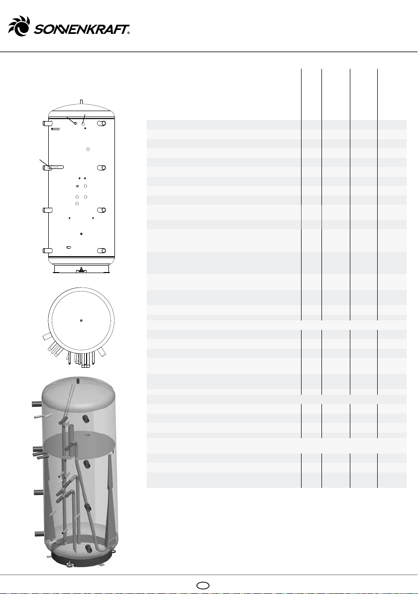
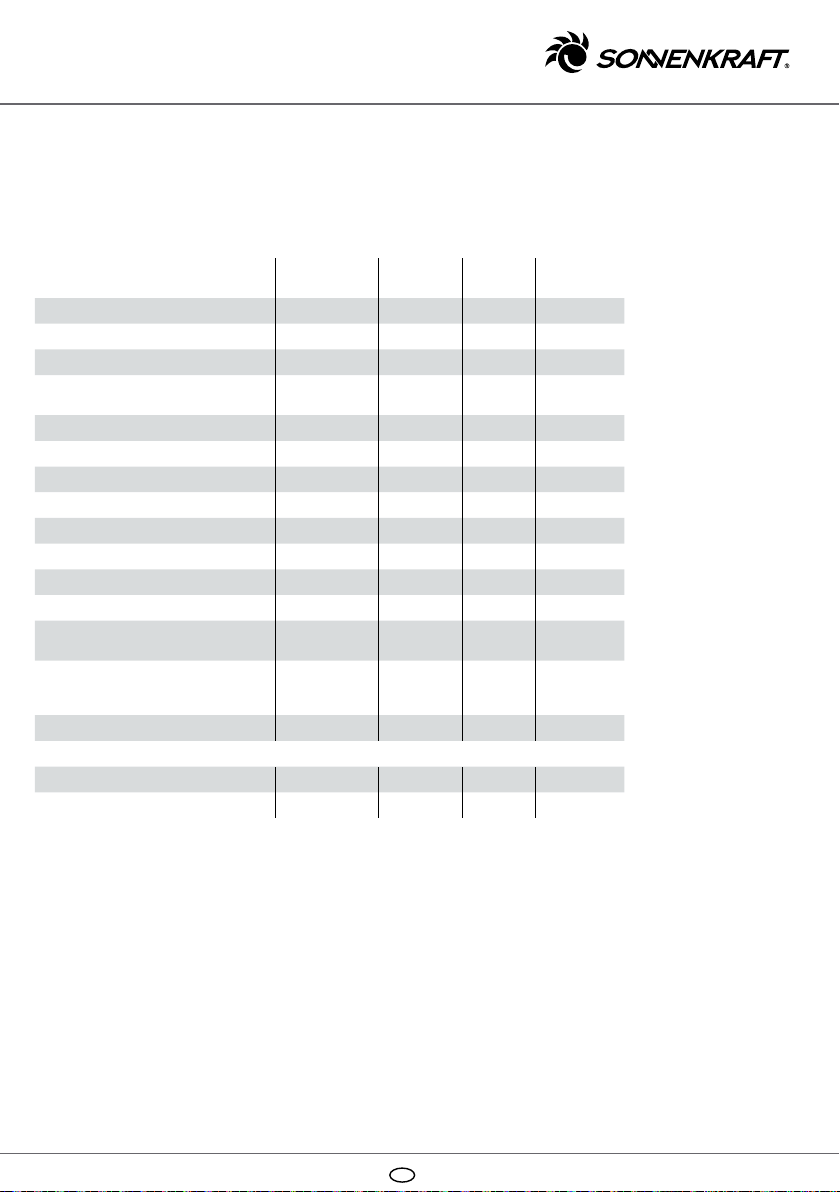
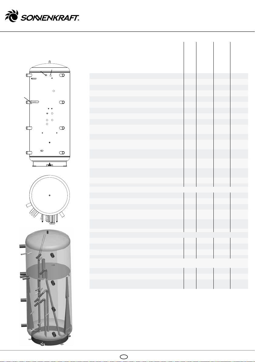
Dati tecnici ...................................................................................................................12
Schema di collegamento ..........................................................................12
Ricambi/Accessori ........................................................................................... 13
Montaggio
La collocazione e l'installazione devono essere eseguite
da una ditta specializzata e autorizzata!
Si consiglia di smontare l'isolamento premontato in
tessuto/non tessuto per ridurre l'ingombro durante il
trasporto.
La collocazione deve avvenire in un ambiente non sog-
getto a gelo e con brevi percorsi per le condutture.
Per l’installazione in zone del tetto, prevedere una vasca
di raccolta adeguata, con possibilità di scarico dell'ac-
qua. Per l'impiego dei piedini regolabili in altezza, questi
devono essere avvitati prima del posizionamento del
serbatoio, al fine di poterlo collocare nel locale di posa in
posizione verticale.
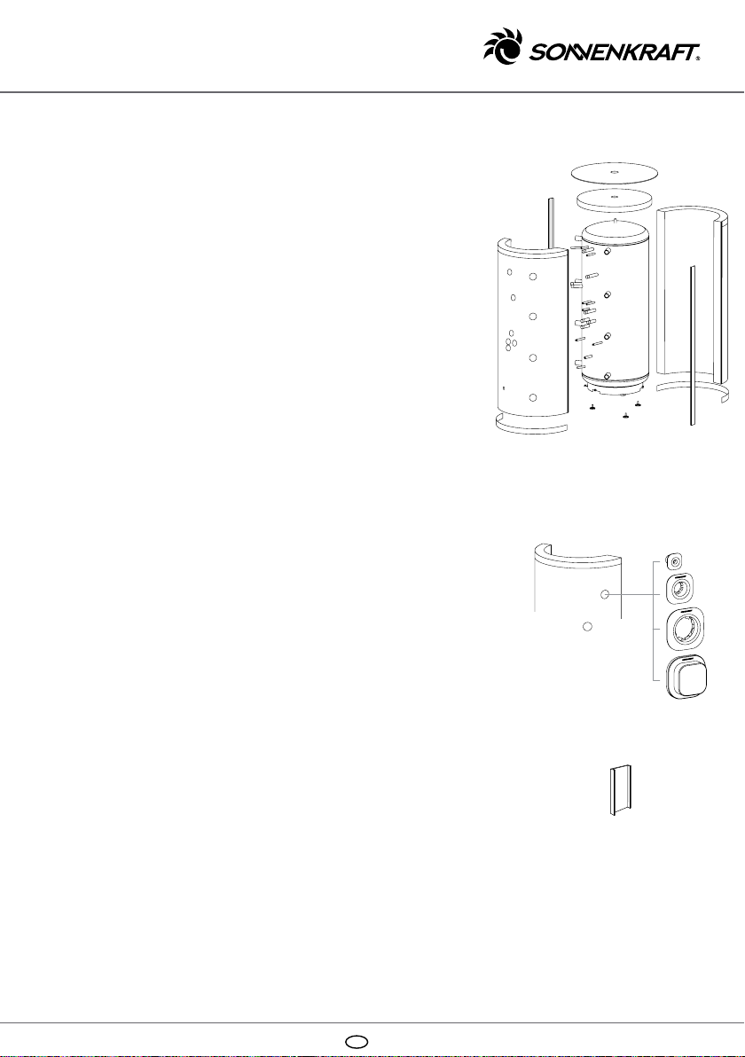
Isolamento
Sequenza di montaggio dell'isolamento in tessuto/non
tessuto con rivestimento in polistirolo:
1. Applicazione del coperchio isolante in tessuto/non
tessuto in alto sul serbatoio (verificare la posizione
corretta).
2. Innanzitutto posizionare con cura la metà forata
dell'isolamento senza uso di forza eccessiva intorno
al serbatoio.
3. Posizionare la seconda metà dell'isolamento intorno al
serbatoio. Collegare per prima cosa le due metà dell'i-
solamento su un lato mediante il listello di chiusura a
ganci, posizionando in primo luogo i ganci nella prima
scanalatura.
4. Adattare le due metà dell'isolamento con cura e
senza uso di forza eccessiva al serbatoio e collegarle
mediante il secondo listello a ganci.
121 428 – 121 431 / Version 2012/01

I11
Nota
Fate in modo che il vaso di espan-
sione nel circuito di riscaldamento
abbia dimensioni adeguate. Nel
calcolo occorre considerare anche
il volume tampone nonché gli
sbalzi di temperatura che si
verificano negli impianti solari.
5. Serrare entrambi i listelli di chiusura a ganci partendo
dall'alto o dal basso, gancio dopo gancio, fino a quando
si innestano nell'ultimo gancio. Per il fissaggio è possibi-
le utilizzare i supporti di montaggio (listelli di copertura
corti).
6. Posizionare la piastra di copertura del serbatoio.
7. Serrare i listelli di copertura mediante i ganci
di chiusura.
8. Se necessario utilizzare rosette/cappe.
9. Infine incollare i due battiscopa forniti in dotazione
sull'estremità inferiore dell'isolamento.
Avvertenza: non montare l'isolamento con una temperatu-
ra ambiente inferiore a 10 °C o non spingerlo contro ogget-
ti duri, poiché possono verificarsi rotture bianche nella
superficie in polistirolo.
Messa in servizio
Il primo riempimento e la messa in servizio, devono essere
eseguiti da una ditta specializzata autorizzata. A que-
sto proposito verificare funzione e la tenuta dell'interno
impianto inclusi i pezzi montati nell'azienda produttrice.
La perfetta funzionalità della valvola di sicurezza e lo
sfiato del serbatoio devono essere verificati a intervalli
regolari. Si consiglia di eseguire la manutenzione una volta
all'anno da parte di una ditta specializzata. Non utilizzare
il serbatoio sopra i 95 ° C . Le sovrappressioni di esercizio
indicate sulla targhetta identificativa non devono essere
superate.
Elemento riscaldante elettrico
I gruppi di riscaldatori elettrici possono essere collegati
soltanto da installatori elettrici autorizzati secondo lo schema
corrispondente. Osservare rigorosamente le indicazioni del
fornitore di energia elettrica.
Il riscaldatore elettrico (se disponibile) deve essere sottoposto
a decalcificazione ogni anno, o anche più spesso se la durezza
dell'acqua lo richiede. A questa operazione si
deve aggiungere
un controllo sul funzionamento.
Gli elementi riscaldanti elettrici avvitabili sono ammessi
soltanto come mezzo di riscaldamento aggiuntivo!
Specificazioni sulla garanzia
Sulla smaltatura del serbatoio e contro la formazione
di ruggine il fornitore concede una garanzia di
5 anni a partire dalla data della fattura d'acquisto.
Su tutti gli accessori vale una garanzia di due anni
a partire dalla data della fattura d'acquisto.
Fig.: PSC incl. accessorio
isolante
Fig.: rosette incl. coperchio
Fig.: supporto di montaggio

I
12
Schema di
collegamento Dati tecnici
Gli elementi riscaldanti elettrici EHP possono
essere montati nei manicotti A, B e C.
SLM-L/R/O: manicotto di fissaggio M8 in alto o a sinistra/destra
per modulo di caricamento a stratificazione SLM50HE
HKM-BH (RAS-BH): manicotto di fissaggio M8 per modulo circuito
di riscaldamento HKM20 o stazione di sollevamento ritorno RAS20
FWM-L/R/U: perno di ancoraggio in alto a sinistra/destra o manicotto
di fissaggio M10 in basso per modulo acqua sanitaria FWMi
HKM-BH (RAS-BH)
A
D
C
B
EL
F-SLMO/WW
SLM-O
SLMM
HKM-RL (RAS-RL)
FWM-RLU
SLM-L
F-HKM (F-RAS)
FWM-L
SLMO
A
D
C
B
HKM-VL (RAS-VL)
SLM-R
SLMU
FWM-RLM
FWM-VL
FWM-R
FWM-U
F-SLMU/S
Unità
Ø raccordo
PSC800E
PSC1000E
Contenuto l - 810 995
Diametro con isolamento
mm -
990 990
Diametro senza isolamento mm - 790 790
Altezza con isolamento mm - 1860 2140
Altezza senza isolamento mm - 1778 2058
Misura di ribaltamento senza isolamento mm - 1830 2100
Peso (senza isolamento) kg - 111 123
Pressione di esercizio cons. per riscaldamento bar - 3 3
Temperatura di esercizio cons. per riscaldamento ° C - 95 95
Dispersione termica in standby secondo DIN 4753/8
(ΔT 45K), calcolata kWh/d -3,4 3,7
Tasso di dispersione termica secondo EN 12977 W/K -3,12 3,46
Manicotto A, 2 x (ad es. mandata caldaia per riscal-
damento integrativo acqua calda KVWW o resistenza
elettrica di riscaldamento EHP)
mm
Rp 6/4"
1450 1780
Manicotto B, 2 x (ad es. mandata per riscaldamento
VL-HZ, resistenza elettrica di riscaldamento EHP
oppure mandata caldaia per riscaldamento
integrativo KV-HZ)
mm
Rp 6/4"
1030 1250
Manicotto C, 2 x (ad es. ritorno per riscaldamento
RL-HZ o resistenza elettrica di riscaldamento EHP) mm
Rp 6/4"
630 745
Manicotto D, 2 x (ad es. ritorno per riscaldamento a
pavimento RL-FBHZ, svuotamento) mm
Rp 6/4"
260 260
Sfiato dell'aria EL mm
Rp 1/2"
top top
Raccordi modulo di caricamento a stratificazione SLM50HE
SLMO mandata "in alto" mm G 1" 1670 1770
SLMM mandata "centro" mm G 1" 1370 1470
SLMU ritorno "in basso" mm G 1" 930 1030
F-SLMO/WW - guaina ad immersione per sensore SLM
"in alto"/acqua calda mm Di 15 x
100 1500 1780
F-SLMU/S - guaina ad immersione per sensore SLM
"in basso"/solare mm Di 15 x
100 300 300
Raccordi modulo acqua sanitaria FWMi
FWM-VL mandata
mm
G 1"
800 900
FWM-RLM ritorno "centro" mm G 1" 722 822
FWM-RLU ritorno "in basso" mm G 1" 800 900
Attacchi modulo circuito di riscaldamento HKM20 / stazione di sollevamento ritorno
RAS20
HKM-VL/RAS-VL mandata mm G 1" 1158 1258
HKM-RL/RAS-RL ritorno mm G 1" 1158 1258
F-HKM/F-RAS guaina ad immersione per sensore mm Di 15 x
100 930 1030

I13
Le illustrazioni riportate hanno carattere puramente rappresentativo. A motivo di possibili errori nella
composizione e nella stampa, nonché delle necessarie modifiche tecniche, chiediamo comprensione
se decliniamo ogni responsabilità riguardo alla correttezza dei contenuti. Si rimanda alla validità delle
condizioni generali di contratto nella stesura al momento valida.
Ricambi/Accessori
Descrizione articolo Denominazione
articolo N. art. PSC800E PSC1000E
Ricambi
Isolamento tessuto/non tessuto
per PSC800E ISOVPSC800 121952 •
Isolamento tessuto/non tessuto
per PSC1000E ISOVPSC1000 121953 •
Piastra di copertura del serbatoio
per PS/PSC 800E/1000E ISOVPSD990 121962 • •
Listello di copertura per PS/PSC 800E ISOVPS800AL 121963 •
Listello di copertura per PS/PSC
1000E ISOVPS1000AL 121964 •
Coperchio tessuto/non tessuto
per PSC800E/1000E ISOVPSCVD790 121965 • •
Battiscopa per PS/PSC 800E/1000E ISOVPSFL990 121966 • •
Rosetta tubo sensore, quadra ISOV-ROSFRE 121967 • •
Rosetta 1'', quadra ISOV-ROS25E 121968 • •
Rosetta 6/4",
quadra D 114 x d 52 x 36 '' ISOV-ROS40E 121969 • •
Cappa isolante 6/4",
quadra D 119 x d 89 x 39'' ISOV-KAP40E 121970 • •
Sacchetto rosette/cappe per
PSC800E/1000E ISOVPSCROS 121971 • •
Gomma di raccordo Omega
per tubo sensore Di 15 mm,
adatta per 3 sensori con Ø 6 mm
OMEGA-AKF 120054 • •
Piedini regolabili M12,
sacchetto (3 pezzi) PS-SF 120000 • •
Accessori
Tubo flessibile di raccordo
accumulatore PVS40 120026 • •
Manicotto di prolungamento
accumulatore, 200 mm PVS40-200 PVS40-200 • •

F
14
Consignes de sécurité
Veuillez lire les consignes sui-
vantes concernant la mise en
service et le montage avant de
mettre votre installation en ser-
vice. Vous éviterez ainsi d'endom-
mager votre installation en raison
d'une utilisation non conforme
de celle-ci. Une utilisation non
conforme et des modifications
non autorisées lors du montage
et sur l'installation provoquent
l'annulation des droits à garantie.
Les règles suivantes de la tech-
nique doivent être particulière-
ment respectées, ainsi que les
règlementations nationales en
vigueur.
DIN 1988
Règles techniques concernant
les installations d'eau potable.
DIN-4753
Chauffe-eau et installation de
préparation d'eau chaude pour
l'eau potable et de service; exi-
gences, marquage, équipement
et contrôle
DIN 4751
Equipement technique de sécurité
des installations de chauffage
DIN 18380
Installations de chauffage et
installations centrales de
préparation d'eau chaude
DIN-18381
Installations d'eau, de gaz et
d'évacuation des eaux usées
DIN 4757
Installations de chauffage solaire/
thermosolaire
EN 12975
Systèmes à chauffage solaire
thermique et leurs composants
VDI 2035
Prévention des dommages dans
les installations de chauffage à
eau chaude
Sommaire
Consignes de sécurité ................................................................................14
Montage ............................................................................................................................14
Isolation ............................................................................................................................14
Mise en service ....................................................................................................15
Corps électrique de chauffe ..............................................................15
Conditions de garantie ..............................................................................15
Caractéristiques techniques .............................................................16
Schéma de raccordement .....................................................................16
Accessoires/pièces de rechange ................................................17
Montage
Le montage et l'installation doivent être réalisés par une
entreprise spécialisée agréée !
Il est recommandé de démonter l'isolation en non-tissé
pré-montée afin de réduire les cotes d'installation.
Le montage doit être réalisé dans un local protégé contre le
gel et doté de conduites courtes.
En cas d'installation dans des pièces mansardées, une cuve
collectrice appropriée, permettant d'évacuer l'eau doit être
installée. En cas d'utilisation des pieds réglables en hauteur,
ils doivent être vissés avant l'installation du réservoir afin
de pouvoir installer le réservoir verticalement sur le site
d'installation.
Isolation
Ordre de montage de l'isolation en non-tissé avec gaine en
polystyrène :
1. Installation du couvercle isolant en non-tissé sur le haut
du réservoir (veiller à ce qu'il soit bien installé).
2. Commencer par déposer la moitié percée de l'isolation
soigneusement autour du réservoir, sans exercer de
force.
3. Placer la seconde moitié de l'isolation autour du réser-
voir. Ensuite, relier les deux moitiés de l'isolant sur une
face via la barrette de fermeture à crochets, en plaçant
au préalable le crochet dans la première encoche.
4. Ajuster soigneusement les deux moitiés de l'isolation au
réservoir, sans exercer de force excessive, et les relier à
l'aide de la seconde barrette de fermeture à crochets.
5. Resserrer les deux barrettes de fermeture à crochets en
partant du haut ou du bas, crochet par crochet, jusqu'à
ce que vous enclenchiez le dernier crochet. Pour la
fixation, il est possible d'utiliser les aides au montage
(baguettes courtes).
121 428 – 121 431 / Version 2012/01

F15
Remarque
Veillez à ce que le vase d'expan-
sion du circuit de chauffage soit de
dimensions suffisantes. Le volume
tampon et les différences de tem-
pérature apparaissant dans des
installations solaires doivent être
pris en compte dans les calculs.
6. Installer le couvercle du réservoir.
7. Fixer les baguettes à l'aide des fermetures à cro-
chets.
8. En cas de besoin, poser des plaques d'ancrage / des
capuchons.
9. Pour finir, coller les deux plinthes fournies à l'extré-
mité inférieure de l'isolation.
Remarque : ne pas monter l'isolation à une température
inférieure à 10 °C et ne pas l'installer en la poussant
avec des objets durs car une cassure blanche pourrait
survenir au niveau de la surface en polystyrène.
Mise en service
Le premier remplissage et la mise en service doivent
être confiés à une entreprise agréée. Dans ce contexte,
contrôler le fonctionnement et l'étanchéité de l'en-
semble de l'installation, y compris des pièces montées
en usine par le fabricant. La sécurité du fonctionnement
de la soupape de sécurité et du purgeur du réservoir
doit être contrôlée à intervalles réguliers. Une main-
tenance annuelle par une entreprise spécialisée est
recommandée. Ne pas faire fonctionner le réservoir à
plus de 95 ° C . Les surpressions indiquées sur la plaque
signalétique ne doivent pas être dépassées.
Corps électrique de chauffe
Les éléments chauffants doivent être installés unique-
ment par des installateurs agrées, en respectant le
schéma de raccordement. Il et impératif de respecter
les prescriptions du fournisseur d'énergie.
Le chauffage électrique (s'il existe) doit être détratré
tous les ans à des intervalles relatifs à la teneur de
l'eau en calcaire. Ces travaux doivent s'accompagner
d'un contrôle du fonctionnement.
Les radiateurs électriques à insertion doivent être
utilisés exclusivement comme chauffages d'appoint.
Conditions de garantie
Le fournisseur garantit pendant 5 ans à partir de
la date de la facture que le réservoir le rouille pas.
Tous les accessoires font l'objet d'une garantie de
deux ans à partir de la date de la facture.
Fig. : PSC avec accessoires
d'isolation
Fig. : Plaques d'ancrage
avec capuchon
Fig. : Aide au montage

F
16
Schéma de raccordement Caractéristiques techniques
La résistance électrique à insertion EHP peut être montée dans les
manchons A, B et C.
SLM-L/R/O : Douille de fixation M8 haut ou gauche / droite pour module
de chargement par stratification SLM50HE
HKM-BH (RAS-BH) : Douille de fixation M8 pour module du circuit de
chauffage HKM20 ou station d'augmentation du retour RAS20
FWM-L/R/U : Boulon d'accrochage haut gauche / droit ou douille
de fixation M10 bas pour module d'eau sanitaire FWMi
HKM-BH (RAS-BH)
A
D
C
B
EL
F-SLMO/WW
SLM-O
SLMM
HKM-RL (RAS-RL)
FWM-RLU
SLM-L
F-HKM (F-RAS)
FWM-L
SLMO
A
D
C
B
HKM-VL (RAS-VL)
SLM-R
SLMU
FWM-RLM
FWM-VL
FWM-R
FWM-U
F-SLMU/S
Unité
Ø Raccord
PSC800E
PSC1000E
Contenance l - 810 995
Diamètre avec isolation
mm -
990 990
Diamètre sans isolation mm - 790 790
Hauteur avec isolation mm - 1860 2140
Hauteur sans isolation mm - 1778 2058
Cote inclinée sans isolation mm - 1830 2100
Poids (non isolé) kg - 111 123
Pression de service adm. chauffage bars - 3 3
Température de service adm. chauffage °C - 95 95
Pertes de chaleur au départ selon DIN 4753/8 (ΔT 45K),
calculées kWh/d -3,4 3,7
Taux de pertes de chaleur selon EN 12977 W/K -3,12 3,46
Manchon A, 2 x (par ex. aller chaudière
pour réchauffage eau chaude KVWW
ou cartouche chauffage électrique EHP)
mm
Rp 6/4"
1450 1780
Manchon B, 2 x (par ex. aller pour chauffage VL-HZ,
cartouche chauffage électrique EHP
ou aller chaudière pour réchauffage KV-HZ)
mm
Rp 6/4"
1030 1250
Manchon C, 2 x (par ex. retour pour chauffage RL-HZ
ou cartouche chauffage électrique EHP) mm
Rp 6/4"
630 745
Manchon D, 2 x (par ex. retour pour chauffage
au sol RL-FBHZ, purge) mm
Rp 6/4"
260 260
Purge EL mm
Rp 1/2"
top top
Raccords module de chargement par stratification SLM50HE
SLMO Aller « Haut » mm G 1" 1670 1770
SLMM Aller « Milieu » mm G 1" 1370 1470
SLMU Retour « Bas » mm G 1" 930 1030
F-SLMO/WW - Doigt de gant pour sonde SLM
« Haut » / Eau chaude mm Di 15 x
100 1500 1780
F-SLMU/S - Doigt de gant pour sonde SLM
« Bas » / Solaire mm Di 15 x
100 300 300
Raccords module d'eau sanitaire FWMi
Aller FWM-VL
mm
G 1"
800 900
FWM-RLM Retour « Milieu » mm G 1" 722 822
FWM-RLU Retour « Bas » mm G 1" 800 900
Raccords module du circuit de chauffage HKM20 / Station d'augmentation du retour
RAS20
HKM-VL/RAS-VL Aller mm G 1" 1158 1258
HKM-RL/RAS-RL Retour mm G 1" 1158 1258
F-HKM/F-RAS Doigt de gant pour sonde mm Di 15 x
100 930 1030

F17
Les illustrations utilisées sont des photos-types. En raison d'éventuelles erreurs de
frappe ou d'impression et des modifications techniques permanentes nécessaires,
nous ne pouvons assumer la responsabilité de l'exactitude des informations.
Voir les conditions générales de vente en vigueur.
Accessoires/pièces de rechange
Description de l'article Désignation
de l'article Réf. PSC800E PSC1000E
Pièces de rechange
Isolation non-tissé pour PSC800E ISOVPSC800 121952 •
Isolation non-tissé pour PSC1000E ISOVPSC1000 121953 •
Couvercle de réservoir
pour PS/PSC 800E/1000E ISOVPSD990 121962 • •
Baguette pour PS/PSC 800E ISOVPS800AL 121963 •
Baguette pour PS/PSC 1000E ISOVPS1000AL 121964 •
Couvercle non-tissé pour
PSC800E/1000E ISOVPSCVD790 121965 • •
Plinthe pour PS/PSC 800E/1000E ISOVPSFL990 121966 • •
Plaque d'ancrage pour tube de sonde,
carrée ISOV-ROSFRE 121967 • •
Plaque d'ancrage 1", carrée ISOV-ROS25E 121968 • •
Plaque d'ancrage 6/4",
carrée D 114 x d 52 x 36 " ISOV-ROS40E 121969 • •
Capuchon isolant 6/4",
carré D 119 x d 89 x 39" ISOV-KAP40E 121970 • •
Sachet plaques d'ancrage / capuchons
pour PSC800E/1000E ISOVPSCROS 121971 • •
Ressort d'accouplement Omega
pour tube de sonde Di 15 mm,
adapté pour 3 sondes avec Ø 6 mm
OMEGA-AKF 120054 • •
Pieds réglables M12, sachet (3 pièces) PS-SF 120000 • •
Accessoires
Flexible de raccordement pour tampon PVS40 120026 • •
Manchon de rallonge pour tampon,
200 mm PVS40-200 PVS40-200 • •

E
18
Advertencias de
seguridad
Antes de poner su equipo en ser-
vicio, lea cuidadosamente las
si guientes indicaciones sobre el
mon taje y la puesta en servicio.
De este modo evitará que se pro-
duzcan daños en la instalación
como con secuencia de un manejo
incorrecto. El uso no adecuado, así
como las modificaciones no per-
mitidas durante el montaje y en la
construcción conllevan la pérdida
de los derechos de garantía.
Los siguientes reglamentos de la
técnica deben ser especialmente
observados, al igual que las dispo-
siciones vigentes específicas de
cada país:
DIN 1988
Reglamento técnico para instala-
ciones de agua potable
DIN 4753
Calentadores e instalaciones para
el calentamiento de agua potable y
agua de servicio industrial; requisi-
tos, identificación, equipamiento y
verificación.
DIN 4751
Equipamiento de seguridad técnica
de instalaciones de calefacción
DIN 18380
Instalaciones de calefacción e
instalaciones centralizadas de
producción de agua caliente
DIN 18381
Instalaciones de gas, agua y aguas
residuales
DIN 4757
Instalaciones de calentamiento
solar y termosolar
EN 12975
Instalaciones solares térmicas y
su construcción
VDI 2035
Evitar daños en las instalaciones
del agua caliente y de la calefac-
ciónlistón
Índice
Advertencias de seguridad ................................................................. 18
Montaje ............................................................................................................................ 18
Aislamiento .................................................................................................................. 18
Puesta en servicio ...........................................................................................19
Unidades calefactoras .................................................................................19
Condiciones de garantía ...........................................................................19
Datos técnicos ...................................................................................................... 20
Esquema de conexiones ........................................................................ 20
Piezas de repuesto / Accesorios ............................................... 21
Montaje
¡La colocación e instalación deben ser realizadas
por una empresa especializada y autorizada!
Se recomienda desmontar el aislamiento de vellón pre-
montado para reducir las medidas de colocación.
La colocación se debe realizar en una habitación sin peli-
gro de congelación y con trayectos de tuberías cortos.
Para la colocación en desvanes se debe instalar un recipi-
ente de captación apropiado con posibilidad de evacuación
de agua. Para utilizar las patas de altura regulable, estas
deben desatornillarse antes de montarse para colocar el
acumulador en posición vertical en el lugar de montaje.
Aislamiento
Secuencia de montaje del aislamiento de vellón con reve-
stimiento de poliestirol:
1. Colocación de la tapa de aislamiento de vellón en el
acumulador superior (colocar en el lugar correcto).
2. En primer lugar, colocar con cuidado la mitad perforada
del aislamiento alrededor del acumulador sin ejercer
una fuerza excesiva.
3. Colocar la segunda mitad del aislamiento alrededor
del acumulador. Unir las dos mitades del aislamiento a
través del listón de cierre con gancho, primero por una
parte, colocando en primer lugar el gancho en la prime-
ra acanaladura.
4. Adaptar las dos mitades del aislamiento al acumulador
con cuidado y sin ejercer una fuerza excesiva, y unirlas
mediante el segundo listón de gancho.
5. Tensar gancho por gancho los dos listones de cierre de
gancho, empezando por arriba o por abajo, hasta que
encajen en el último gancho. Para fijarlos se pueden
utilizar elementos auxiliares de montaje (listones cober-
tores cortos).
6. Colocar la placa de cubierta del acumulador.
121 428 – 121 431 / Version 2012/01

E19
Nota
Asegúrese de que el dimen sionado
del depósito de expansión en el
circuito de calefacción sea sufi-
ciente. En el cálculo se deben
tener en cuenta el volumen del
acumulador intermedio, así como
las temperaturas diferenciales que
se produzcan en las instalaciones
solares.
7. Sujetar los listones cobertores mediante los cierres de
gancho.
8. En caso necesario, colocar rosetas/tapas.
9. Por último, adherir los dos rodapiés suministrados al
extremo inferior del aislamiento.
Nota: No monte el aislamiento a una temperatura ambien-
te inferior a 10 °C ni lo presione contra objetos duros, ya
que en las superficies de poliestirol se pueden producir
fracturas blancas.
Puesta en servicio
El primer llenado y la primera puesta en servicio deberán
ser realizados por una empresa especializada autorizada.
Aquí habrá que comprobar el funcionamiento y la estan-
queidad de la instalación completa, incluyendo las piezas
montadas en el taller del fabricante. La seguridad de fun-
cionamiento de la válvula de seguridad y de la ventilación
del acumulador deberá comprobarse a intervalos regu-
lares. Se recomienda encargar un mantenimiento anual a
una empresa especializada. No ponga en funcionamiento
el acumulador a más de 95 ° C . No se deben rebasar
las sobrepresiones de servicio indicadas en la placa de
características.
Unidades calefactoras
Los calefactores eléctricos sólo serán instalados por elec-
tricistas autorizados, y siguiendo el esquema de circuitos
correspondiente. Debe cumplirse obligatoriamente con las
directivas de la empresa suministradora de energía.
Deben retirarse los depósitos de cal del calefactor eléctrico
(en caso de que se use uno) una vez al año, o incluso más
frecuentemente si así lo condiciona la dureza del agua.
En ese momento ha de realizarse una comprobación
de su correcto funcionamiento.
La unidad calefactora roscable sólo se puede emplear
como elemento adicional de calentamiento.
Condiciones de garantía
El proveedor concede una garantía contra la corrosión del
acumulador de 5 años a partir de la fecha de la factura.
Las piezas de repuesto están cubiertas por una garantía
de 2 años a partir de la fecha de la factura.
Fig.: PSC incl. accesorios
de aislamiento
Fig.: Rosetas incl. cubierta
Fig.: Elementos auxiliares
de montaje

E
20
Esquema de conexiones Datos técnicos
Las unidades calefactoras EHP se pueden montar
en los manguitos A, B y C.
SLM-L/R/O: casquillo de fijación M8 arriba o izquierda/derecha
para módulo de estratificación SLM50HE
HKM-BH (RAS-BH): casquillo de fijación M8 para módulo del circuito
de calefacción HKM20 o estación elevadora de retorno RAS20
FWM-L/R/U: perno de enganche arriba a la izquierda/derecha o casquillo
de fijación M10 abajo para módulo de agua fresca FWMi
HKM-BH (RAS-BH)
A
D
C
B
EL
F-SLMO/WW
SLM-O
SLMM
HKM-RL (RAS-RL)
FWM-RLU
SLM-L
F-HKM (F-RAS)
FWM-L
SLMO
A
D
C
B
HKM-VL (RAS-VL)
SLM-R
SLMU
FWM-RLM
FWM-VL
FWM-R
FWM-U
F-SLMU/S
Unidad
Ø conexión
PSC800E
PSC1000E
Contenido l - 810 995
Diámetro con aislamiento
mm -
990 990
Diámetro sin aislamiento mm - 790 790
Altura con aislamiento mm - 1860 2140
Altura sin aislamiento mm - 1778 2058
Medida de inclinación sin aislamiento mm - 1830 2100
Peso (sin aislamiento) kg - 111 123
Presión de servicio autoriz. para calefacción bares - 3 3
Temperatura de servicio autoriz. para calefacción °C - 95 95
Pérdida de calor disponible calculada según DIN 4753/8
(ΔT 45K) kWh/d -3,4 3,7
Tasa de pérdida de calor según EN 12977 W/K -3,12 3,46
Manguito A, 2 x (p. ej. avance de caldera para
recalentamiento de agua caliente KVWW o resistencia
eléctrica EHP)
mm
Rp 6/4"
1450 1780
Manguito B, 2 x (p. ej. avance para calefacción VL-HZ,
resistencia eléctrica EHP o avance de caldera para
recalentamiento KV-HZ)
mm
Rp 6/4"
1030 1250
Manguito C, 2 x (p. ej. retorno para calefacción RL-HZ
o resistencia eléctrica EHP) mm
Rp 6/4"
630 745
Manguito D, 2 x (p. ej. retorno para calefacción de
suelo RL-FBHZ, vaciado) mm
Rp 6/4"
260 260
Ventilación EL mm
Rp 1/2"
top top
Conexiones del módulo de estratificación SLM50HE
Avance SLMO "arriba" mm G 1" 1670 1770
Avance SLMM "centro" mm G 1" 1370 1470
Retorno SLMU "abajo" mm G 1" 930 1030
F-SLMO/WW - Manguito sumergible SLM "arriba"/
agua caliente mm Di 15 x
100 1500 1780
F-SLMU/S - Manguito sumergible del sensor SLM
"abajo"/solar mm Di 15 x
100 300 300
Conexiones de módulo de agua fresca FWMi
FWM-VL avance
mm
G 1"
800 900
FWM-RLM retorno "centro" mm G 1" 722 822
FWM-RLU retorno "abajo" mm G 1" 800 900
Conexiones del módulo del circuito de calefacción HKM20 / estación
elevadora de retorno RAS20
HKM-VL/RAS-VL avance mm G 1" 1158 1258
HKM-RL/RAS-RL retorno mm G 1" 1158 1258
F-HKM/F-RAS manguito sumergible del sensor mm Di 15 x
100 930 1030
Other manuals for PSC-E Series
1
This manual suits for next models
2
Table of contents
Languages:
Other Sonnenkraft Water System manuals
Popular Water System manuals by other brands

DAB
DAB DIVERTEK Instruction for installation and maintenance

Rain Soft
Rain Soft TC Series owner's manual

salmson
salmson Priux home M Installation and starting instructions

Bayrol
Bayrol Pool Relax Chlorine instruction manual

Grundfos
Grundfos Auto ADAPT ALPHA2 Installation and operating instructions

Hilti
Hilti DD-REC1 operating instructions