manuals.online logo
Brands
  1. Home
  2. •
  3. Brands
  4. •
  5. Condair
  6. •
  7. Water System
  8. •
  9. Condair RO-A User manual

Condair RO-A User manual

Humidication and Evaporative Cooling
Pure Water System
Condair RO-A
SERVICE MANUAL
2595203 EN 1902
2Contents
Contents
1 For your safety 3
2 Factory Settings 4
3 Operational malfunctions 8
3For your safety
1 For your safety
General
Every person working with the Condair RO-A pure water system must have read and understood the
Condair RO-A pure water system installation and operation manual before carrying out any work.
Knowing and understanding the contents of this manual is a basic requirement for protecting personnel
against any kind of danger, to prevent faulty operation, and to operate the Condair RO-A pure water
system safely and correctly.
All icons, signs and markings applied to the components of the Condair RO-A pure water system must
be observed and kept in readable state.
Qualication of personnel
The Condair RO-A pure water system must be installed and operated only by persons who are well
trained, and adequately qualied for the respective task and are authorized by the customer.
For safety and warranty reasons any action beyond the scope of this manual must be carried out only
by service personnel authorised by Condair.
It is assumed that all persons working with the Condair RO-A are familiar and comply with the appropriate
regulations on work safety and the prevention of accidents.
The Condair RO-A pure water system may not be used by persons (including children) with reduced
physical, sensory or mental abilities or persons with lacking experience and/or knowledge, unless they
are supervised by a person responsible for their safety or they received instructions on how to operate
the system.
Children must be supervised to make sure that they do not play with the Condair RO-A pure water system.
Danger that may arise from the Condair RO-A pure water system
DANGER!
Risk of electric shock
The Condair RO-A is mains powered. Live parts may be exposed when the unit is open. Tou-
ching live parts may cause severe injury or danger to life.
Prevention: Before carrying out any work set the Condair RO-A out of operation as described in
(switch o󰀨 the unit, unplug mains cable, shut o󰀨 the water supply and depressurise the system) and
secure the unit against inadvertent power-up.
Observe all local safety standards
Observe all local safety standards regarding the handling of mains-powered electrical and electronic
devices, and the design and handling of low-pressure water systems.
Preventing unsafe operation
If it is suspected that safe operation is no longer possible, the Condair RO-A pure water system should
immediately be shut down and secured against accidental power-up.
All persons working with the Condair RO-A pure water system must report any alterations to the system
that may a󰀨ect safety to the owner without delay.
4Factory Settings
2 Factory Settings
With the factory password "0948" you may access the factory settings in the "Factory" submenu as well
as the factory functions in the "Service" submenu.
The Condair RO-A Software is bases on the the Condair RS software. For general factory setting menu,
please refer to the Condair RS service manual.
Press "Menu", Code 0948
Note: Press “Menu” for longer than 4 s, if no keyboard occurs.
Press "Engineering"
Press "Operating Mode" if RO is deactivated
5Factory Settings
Press "Operating Mode"
Press "RO", if RO is already activated
Press "Mode", if RS is activated
Press “RS+RO” if you have a RS with RO-A.
Press "RO", if you have a “standalone” RO-A system.
"CE" for EU
"UL" for North America
On = Unit stops if lltime has exceeded (Error 22)
6Factory Settings
Go back to RO
RO water capacity, depends on the numbers of membranes.
Service hours (count down), depends on the water hardness.
Hygiene Normal = Drain valve with function NC
Hygiene Premium = Drain valve with function NO
PS1 and PS2 Type; do not change these two values, you only need it in
case of another type of pressure sensor.
Register “Flush”
Time for tap water ush after “Power on” or pump start.
Time for RO water ush (to drain) before feeding RO water tank.
Duration of manual drain by drain key.
Register "Water production"
After reaching 1.5 bar (after lling the rst time or after FWA) the system
is ok, = release of green LED.
Start pressure for pump to ll pressure vessel.
Pump stops after reaching 3.0 bar. Do not increase the value to more
than 3.9 bar! See next item!
Maximal pressure. If value exceeded, error E62 will occur.
7Factory Settings
Register "Water production"
If the pressure of RO water not reaches the value of “Pressure Min.” after
10 min, “Min.Timeout” , error W/E 124 will occur.
Timeout until W/E 124 will occur.
Register "Fresh Water Automatic"
Value lower than 0.5 bar means “Tank empty”
If the tank is empty, system waits another 120 s for removing water
completely.
Timeout “Fresh Water Automatic” (FWA) every 23 h, if no demand occurred.
Complete drain of the RO water vessel, draining the system and ll again.
Register "Water Pressure"
Tap water pressure has to be stable min. 10 s.
If “Timeout on”, “Timeout Op” will stay 20 s, even if pressure goes down.
Min. time for tap water, where pressure has to be always present.
After 30 s, error will occur.
Register "Water Pressure"
Minimal needed tap water pressure to start pump.
Hysteresis tap water pressure for pump.
8Operational malfunctions
3 Operational malfunctions
Most operational malfunctions are not caused by faulty equipment but rather by improper installation or
disregarding of planning guidelines. Therefore, a complete fault diagnosis always involves a thorough
examination of the entire system.
Code Message Information
Warning Fault Possible causes Remedy
––– E54 Leakage Leakage monitoring has triggered, RO-A is stopped!
Leakage in the water system detected. Check/seal water supply line, water
drain line, hose connections in side
and outside of the RO-A.
Fuse “F2” on the driver board defec-
tive.
Replace fuse “F2” on the driver
board.
––– E58 Pr.Sens.Inlet Invalid signal from inlet water pressure sensor PS1!
Pressure sensor PS1 not or not cor-
rectly connected.
Check/correctly connect pressure sen-
sor PS1.
Pressure sensor PS1 wrong congured. Correctly congure pressure sensor
PS1.
Pressure sensor PS1 defective. Replace pressure sensor PS1.
––– E59 Pr.Sens.Tank Invalid signal from pressure sensor of the tank!
Pressure sensor PS2 not or not cor-
rectly connected.
Check/correctly connect pressure sen-
sor PS2.
Pressure sensor PS2 wrong congured. Correctly congure pressure sensor
PS2.
Pressure sensor PS2 defective. Replace pressure sensor PS2.
––– E60 Pump Guard Pump guard (over current monitoring) has triggered.
Overcurrent condition occured during
operation of pump. Overcurrent relay
inside the control compartment of
the RO-A has triggered.
Let have the overcurrent relay
inside the control compartment of the
RO-A checked by an electrician.
––– E61 Pump Pressure Pump pressure out of valid range!
Tank pressure out of valid range. Check tank pressure.
––– E62 Tank Pressure Tank pressure out of valid range!
Tank pressure out of valid range. Check tank pressure.
––– E73 FWA Timeout FWA has not been completed within the set time!
Drain blocked. Check/clean drain.
Valves defective. Check/replace valves inside the RO-A.
––– E74 Keep Alive Communication between control board and driver board interrupted.
Driver board not connected. Correctly connect driver board.
Wrong driver board installed. Install and connect correct driver board.
Driver board defective. Replace driver board.
––– E82 Driver Missing Communication with driver board interrupted.
RS485 Bus to driver board interrupted. Contact your representative.
––– E84 Driver defective Unknown fault on driver board
Driver board defective. Replace driver board.
––– E85 Driver ID wrong Driver board ID wrong.
Wrong driver board connected or SAB
address wrong.
Contact your representative.
––– E86 Driver Incompat-
ible
Wrong version of driver board.
Wrong version of driver board. Contact your representative.
9Operational malfunctions
Code Message Information
Warning Fault Possible causes Remedy
––– E87 Local 24VSupply Local 24V voltage on driver board out of valid range!
Short circuit on supply module or supply
module defective.
Contact your representative.
––– E88 Local 5V Supply Local 5V voltage on driver board out of valid range!
Short circuit on supply module or supply
module defective.
Contact your representative.
––– E89 Local Ref Supply Local reference voltage out of valid range!
DC supply faulty or supply line inter-
rupted.
Contact your representative.
––– E91 Pressure Instable Water pressure instable because of missing water!
Shut-off valve in the water supply line
not fully open.
Check/completely open shut-off
valve.
Cross section of the supply line too
small.
Install water supply line with lager cross
section (min. ø10/12 mm).
Optional prelter clogged. Clean optional prelter and replace
lter cartridges.
W92 E92 RO Service The maintenance interval of the RO system service has elapsed. If the system
service is not performed and the maintenance message is not reset within one
week after the maintenance message has appeared a fault message is triggered!
RO system service due. Perform RO system service and reset
maintenance counter.
––– E96 Per. 5V Supply Peripheral 5V supply out of valid range.
5V supply interrupted. Check wiring.
Fuse “F2” on the driver board defec-
tive.
Replace fuse “F2” on the driver
board.
Overload on external connection. Disconnect load on terminal X16.
Overload due to defective pressure
sensor.
Replace pressure sensor.
––– E97 Ext. 24V Supply External 24 V supply faulty. Voltage too high or too low.
Fuse “F2” on the driver board defec-
tive.
Replace fuse “F2” on the driver
board.
Short circuit on external connection. Remedy short circuit.
Overload on external connection. Disconnect load on terminal X16.
––– E98 Ext. 10V Supply External 10 V supply faulty. Voltage too high or too low.
Fuse “F2” on the driver board defec-
tive.
Replace fuse “F2” on the driver
board.
Short circuit on external connection. Remedy short circuit.
Overload on external connection. Disconnect load on terminal X16.
––– E122 Water Missing
The inlet valve is open, but the water pressure is not reached within the set time.
Water supply closed. Check/open shut-off valve in water
supply line.
Optional Prelter clogged.
Replace lter cartridges in the optional
prelter.
Optional Water softener is refreshing. Wait until refreshing (duration approx.
2 h) has nished.
––– E124 Pressure Min The nominal tank pressure is not reached within time.
Water supply closed. Check/open shut-off valve in water
supply line.
Optional Prelter clogged.
Replace lter cartridges in the optional
prelter.
Optional Water softener is refreshing. Wait until refreshing (duration approx.
2 h) has nished.
Code Message Information
Warning Fault Possible causes Remedy
––– E200 IO Inlet Y11 Fault on inlet valve Y11.
Valve electrically not connected or coil
defective.
Correctly connect valve or replace coil .
––– E201 IO Inlet Y12 Fault on drain valve Y12.
Valve electrically not connected or coil
defective.
Correctly connect valve or replace coil .
Notes
Notes
Condair Group AG
Talstrasse 35-37, 8808 Pfä󰀩kon SZ, Switzerland
Phone +41 55 416 61 11, Fax +41 55 588 00 07
info@condair.com, www.condair-group.com
CONSULTING, SALES AND SERVICE:

Other Condair Water System manuals

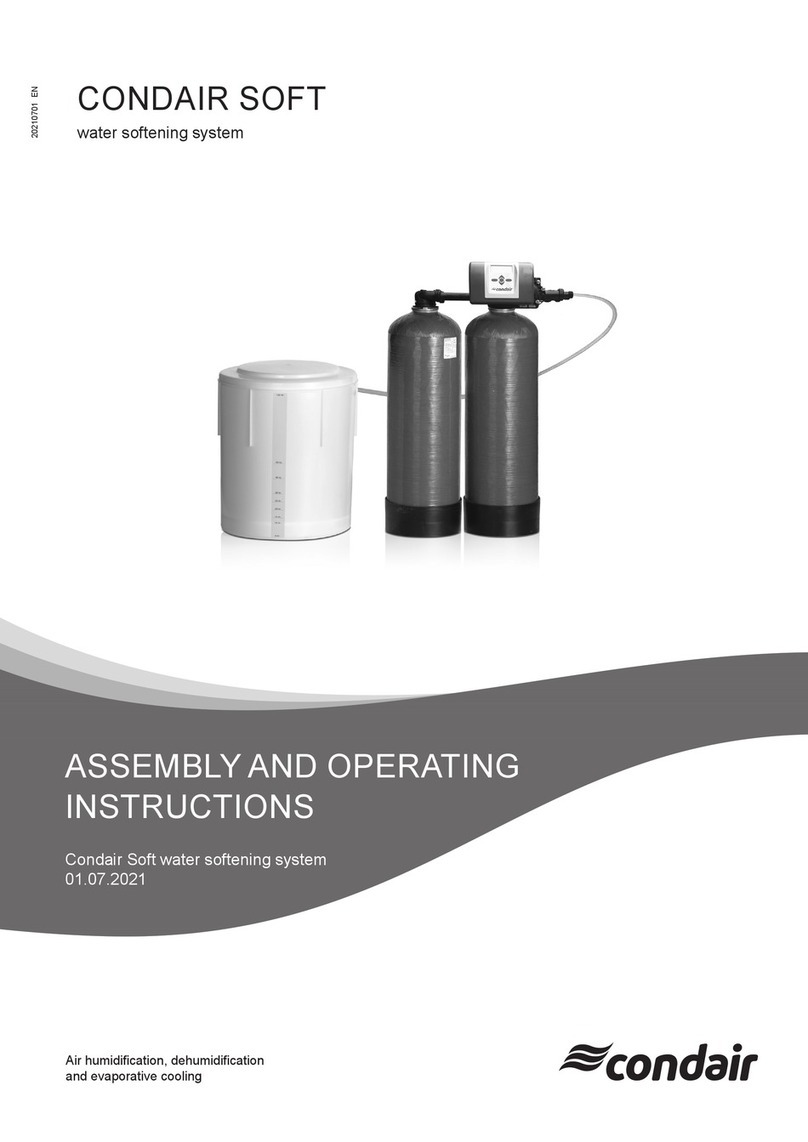
Condair CONDAIR SOFT User manual

Condair

Condair CONDAIR SOFT User manual

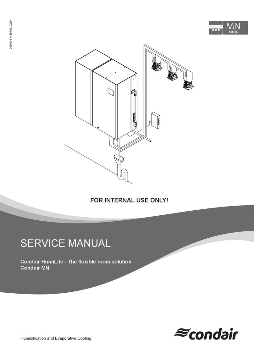
Condair MN Series User manual

Condair

Condair MN Series User manual

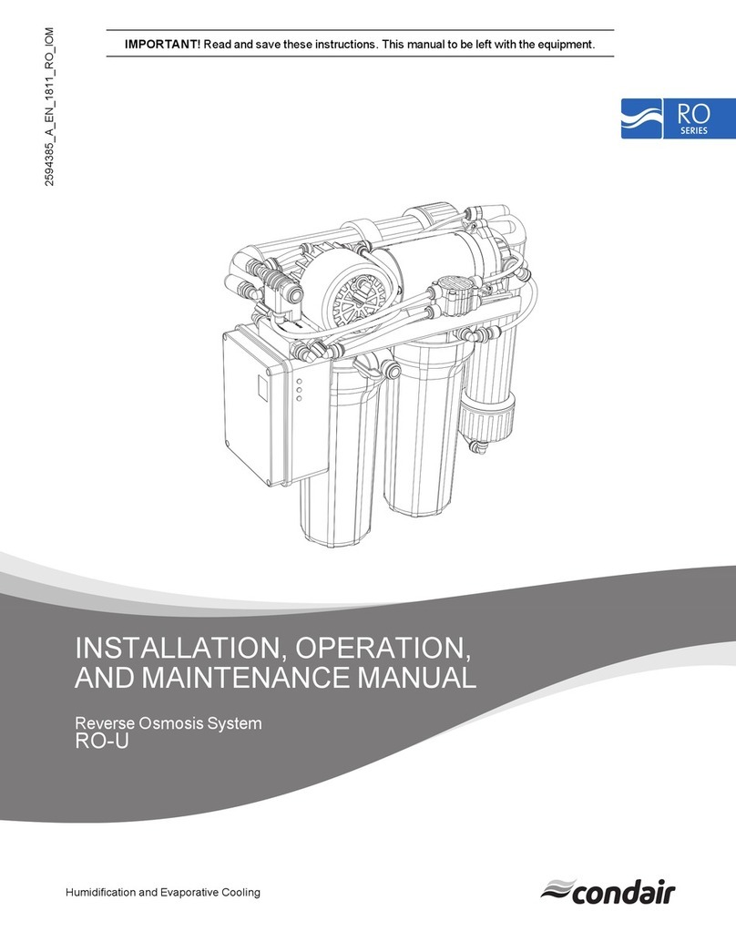
Condair RO-U Installation and operating instructions

Condair

Condair RO-U Installation and operating instructions

Condair RO Series How to use

Condair

Condair RO Series How to use

Condair RO Series User manual

Condair

Condair RO Series User manual

Popular Water System manuals by other brands

JABSCO 31765-0092 manual

JABSCO

JABSCO 31765-0092 manual

ITT LX Series Installation and operating instructions

ITT

ITT LX Series Installation and operating instructions

Culligan Aquasential Salt Free Conditioner 9x16 Condo... owner's guide

Culligan

Culligan Aquasential Salt Free Conditioner 9x16 Condo... owner's guide

P3 International Chemical-Free Water Conditioner NONE Instructions for use

P3 International

P3 International Chemical-Free Water Conditioner NONE Instructions for use

Spectra Watermakers LB-20000 Installation and operating manual

Spectra Watermakers

Spectra Watermakers LB-20000 Installation and operating manual

UNIPRODO WATER SPILLWAY UNI-WATER-25 user manual

UNIPRODO

UNIPRODO WATER SPILLWAY UNI-WATER-25 user manual

Conel Flow Box Installation and operation instruction

Conel

Conel Flow Box Installation and operation instruction

APLOS ANGEL 600 GPD instruction manual

APLOS

APLOS ANGEL 600 GPD instruction manual

CleanWater Tech CD1500P Installation & operation manual

CleanWater Tech

CleanWater Tech CD1500P Installation & operation manual

AQUAMOTION Aqua-Flash AMH1K-6UVZT1 instruction sheet

AQUAMOTION

AQUAMOTION Aqua-Flash AMH1K-6UVZT1 instruction sheet

TECNICOMAR OASI Series INSTRUCTIONS FOR THE INSTALLATION, USE AND MAINTENANCE

TECNICOMAR

TECNICOMAR OASI Series INSTRUCTIONS FOR THE INSTALLATION, USE AND MAINTENANCE

Julabo DYNEO DD-BC4 operating instructions

Julabo

Julabo DYNEO DD-BC4 operating instructions

Everpure Opaque Housing A-11 Specification sheet

Everpure

Everpure Opaque Housing A-11 Specification sheet

REMKO EFS Series Operating and installation instructions

REMKO

REMKO EFS Series Operating and installation instructions

BWT D1 Installation and operating instructions

BWT

BWT D1 Installation and operating instructions

DAB e.sybox Series manual

DAB

DAB e.sybox Series manual

ROPV R80 S Series user manual

ROPV

ROPV R80 S Series user manual

GE GNPR40L Owner's manual and installation instructions

GE

GE GNPR40L Owner's manual and installation instructions

manuals.online logo
manuals.online logoBrands
  • About & Mission
  • Contact us
  • Privacy Policy
  • Terms and Conditions

Copyright 2025 Manuals.Online. All Rights Reserved.