Conductive Labs MRCC 880 User manual

CONDUCYIVE LABS
880 User Guide
.

2
Contents
Support ........................................................................................................ 3
What’s in the box ......................................................................................... 4
Requirements............................................................................................... 4
Specifications ............................................................................................... 4
Precautions .................................................................................................. 5
Getting Started............................................................................................. 6
Overview of MRCC 880 Controls and Ports................................................ 7
Routing DIN Connections .......................................................................... 8
Routing USB MIDI Virtual Inputs (from DAW to DIN) ................................. 8
Routing DIN Inputs to USB Virtual Outputs (from DIN to DAW) ................. 9
Check Your Routings ................................................................................. 9
Saving and Loading Presets........................................................................... 9
Using the MIDI Panic Button ....................................................................... 10
Using MIDI Channel Split Mode .................................................................. 11
Using the Clock Filter.................................................................................. 11
Using the SSC (Start/Stop/Continue) Filter.................................................. 11
Using the MIDI Monitor Mode.................................................................... 12
Using MRCC 880 as an MRCC MIDI Router Control Center Expansion.......... 12
Using More than One MRCC 880 ................................................................ 13
MIDI System Exclusive (SysEx) Messages..................................................... 14
Firmware Updates...................................................................................... 14
Regulatory Compliance............................................................................... 15

3
Welcome, and thank you for choosing Conductive Labs for your MIDI studio
needs! We really appreciate it! If you would be so kind, tag your social media
posts with #MRCC so we can find them. We would love to see how MRCC 880
improves your studio and makes it a better place to create. Share your stories,
music and pictures on our forums in the “Show me what you got!” section.
Sincerely,
Steve and Darryl
Support for MRCC 880 is provided by Conductive Labs and our experienced
users on the Conductive Labs forums.Please register on the forums for
questions not answered in this guide or the MRCC User Manual. As part of
forum registration, you will receive a verification email. If you do not receive it
check your spam/junk folder, the verification emails sometimes end up there. If
you experience any problem with registering on the forums, let us know using
the contact page on our website and we’ll get you set up. You can register on
the forums at: https://conductivelabs.com/forum
You may also want to check the FAQs which answer common questions,
provide usage tips, and other important details that are outside the scope of
this manual.
Opt-in to our Newsletter at conductivelabs.com for new product
announcements and product update news.

4
What’s in the box
1. MRCC 880 MIDI Router
2. USB Type A to Type B cable, 2M
3. This Guide
Requirements
Power supply (not included): USB 5V DC, 80mA. Virtually any USB 2.0 or greater
host port or quality phone charger will be sufficient.
Operating Requirements:
Works with USB hosts that support USB MIDI class compliant devices; including
Conductive Labs MRCC, Microsoft Windows 10 and 11 PCs, MacOS, iPad, and
iPhone, most Android tablets and phones, and Linux too.
Software such as a Digital Audio Workstation (DAW) is required to send MIDI
data from your PC to the MRCC 880.
Specifications
The MRCC may be used as a 4x4 standalone MIDI router or can be used with a
PC/MAC or other USB Host device for 8x8 routable ports.
•Four 5 pin DIN inputs. One shared 3.5MM TRS MIDI Type A jack, choose 5
pin DIN 1 or A jack but not both.
•Four 5 pin DIN outputs, with 3.5MM TRS MIDI thru Type A jack. Both can be
used at once , sharing the same routing.
•One USB 2.0 type B socket for connecting to your PC or USB power supply
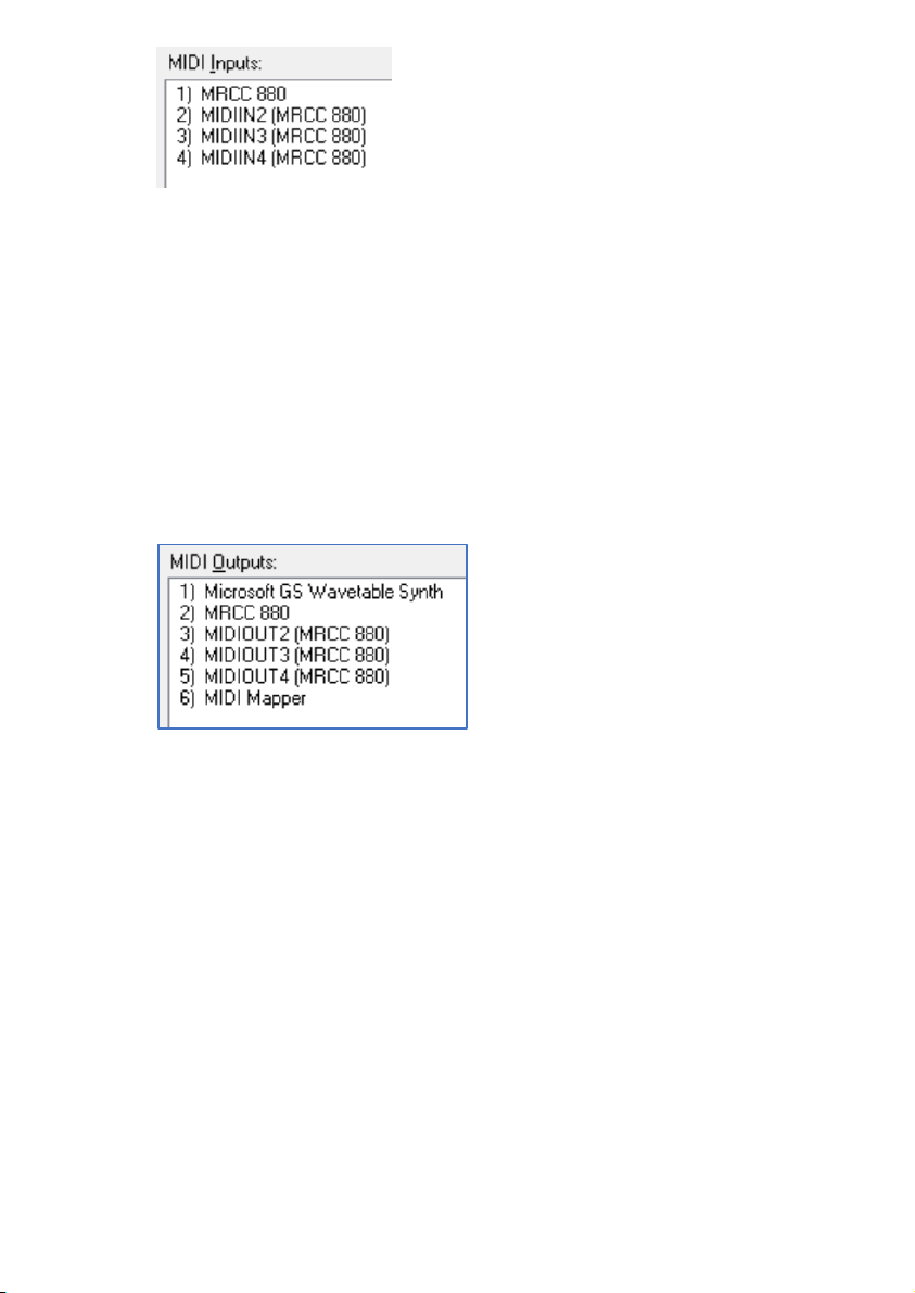
for a DAWless setup. Four USB MIDI virtual inputs and four outputs
individually routable.
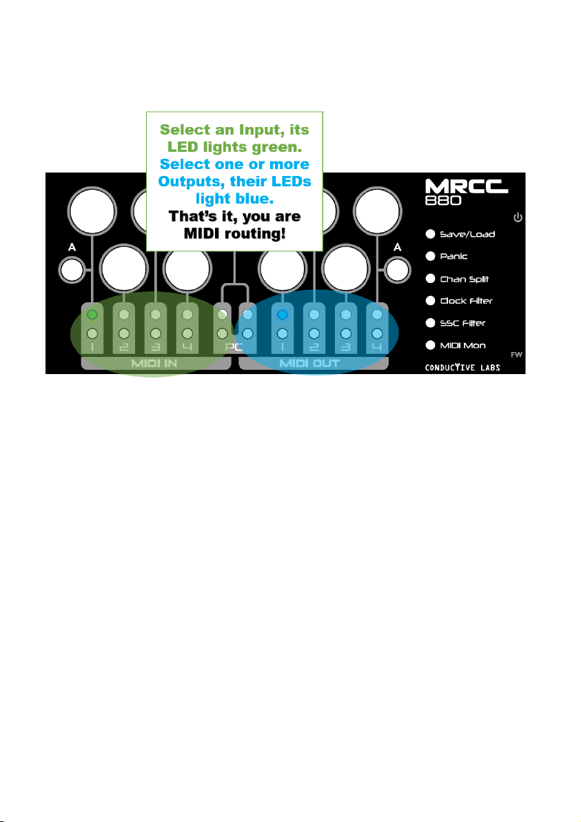
•Green LED indicators for Inputs and Blue indicators for Outputs.
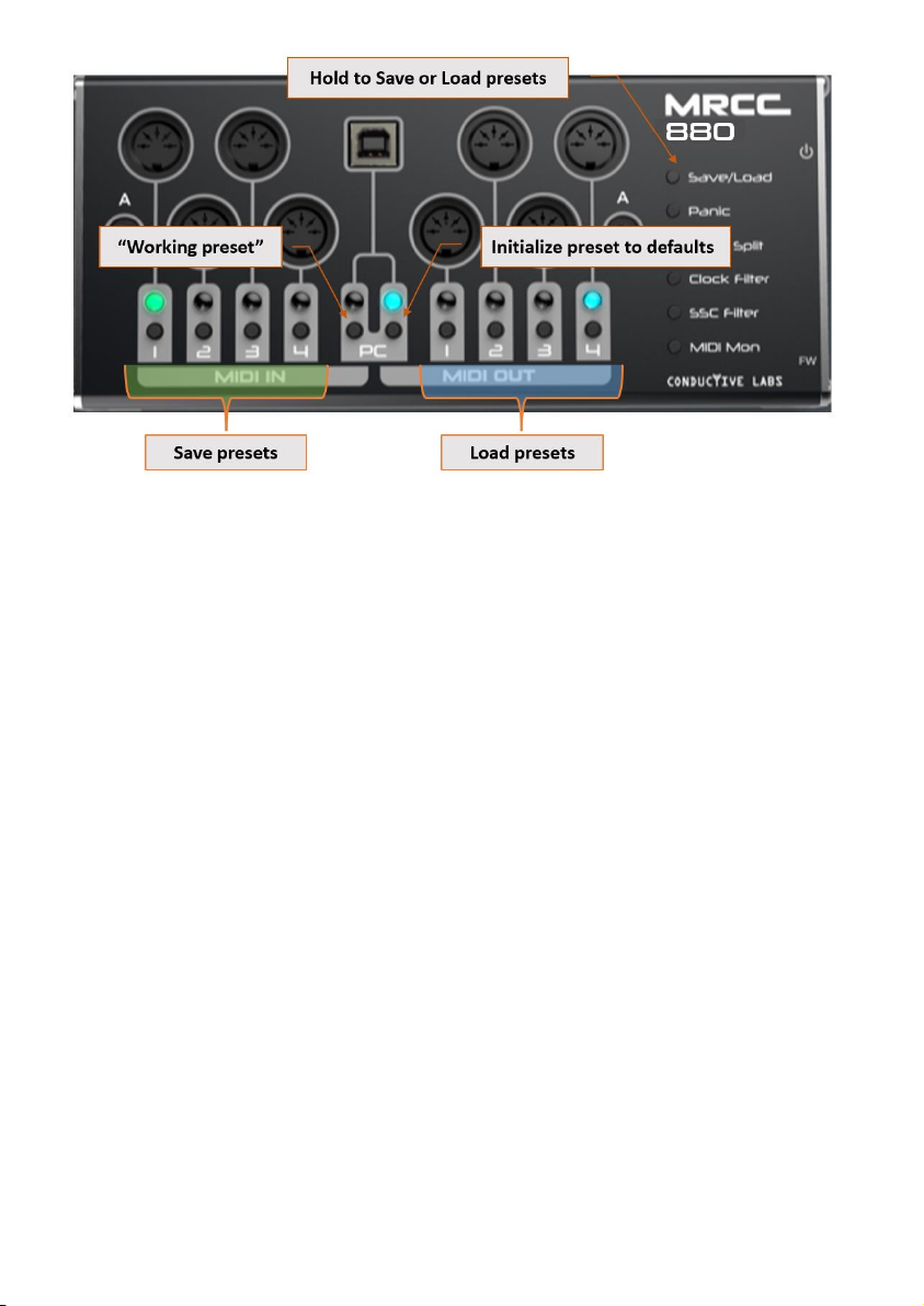
•Save/Load 4x presets, plus Init and “working” presets.
•Dedicated buttons for Save/Load presets, MIDI Panic, Channel Splitter,
Clock Filter, Start/Stop/Continue Filter, MIDI monitor mode, and dedicated
power switch and recessed firmware update button.
•Automatic MIDI merging when different inputs are routed to a common
output.

5
Precautions, not limited to:
1. Read and follow all instructions.
2. Unplug before cleaning and use only a soft dry cloth. Do not use any
cleaners, it could damage the silkscreen ink.
3. Do not use the instrument near water or moisture, such as a bathtub, sink,
swimming pool or similar place.
4. Do not expose the instrument to hot sunlight.
5. Do not spill any kind of liquid onto the instrument.
6. Do not place the instrument in an unstable position where it might
accidentally fall. Do not place heavy objects on the instrument.
7. Do not open or insert anything into the instrument that may cause a fire or
electrical shock.
8. Always contact Conductive Labs LLC if you have an issue. You will invalidate
your warranty if you open and remove the cover unless instructed to do so by
Conductive Labs.
9. Do not use the instrument when there is a gas leak nearby.
10. Conductive Labs LLC is not responsible for any damage or data loss caused
by improper operation of the instrument.
Not following the above Precautions will void the manufacturer’s warranty.

6
Getting Started
1. MRCC 880 is powered by the USB Type B port connection. Connect the
included USB cable between the MRCC 880 and your PC or USB power
supply (not included).
2. Turn on the power switch and the LEDs will light briefly in sequence, then
will light an Input when it’s ready.
3. Connect MIDI input devices such as keyboards and sequencers to the MIDI
DIN inputs.
Note: the 3.5MM jacks labeled “A” are MIDI TRS standard inputs and
outputs. You can choose one of the inputs (A or DIN 1). Do not connect
more than one device to an Input with a shared jack.
4. Connect MIDI sound modules, such as synthesizers to the MIDI outputs.
Note: You can use the A and DIN Outputs simultaneously, they will send
the same MIDI data, so be aware of channel choices.
Hint: Life will be rainbows and unicorns if your hardware MIDI controllers
and sound modules are labeled with their assigned MIDI channels!
5. Set up your DAW (Digital Audio Workstation), if you use one. Each DAW
will have different configuration steps best described by the vendor of the
DAW. YouTube.com is a good resource for learning how to setup a MIDI
interface with your specific system, MIDI interfaces mostly work the same.
Check your DAW documentation for setting up MIDI tracks and virtual
instruments, such as VSTs. For MacOS, use Audio MIDI Setup. See
support.apple.com for details.

7
Overview of MRCC 880 Controls and Ports
(h) = Press and hold the button while selecting an input port to apply the filter
to. MRCC 880 will blink the LEDs to indicate appropriate port choices.
Note: The MRCC provides 3.5MM MIDI TRS type “A” jacks as adopted by the
MIDI Association. However, before the standard was adopted different
manufacturers implemented MIDI on TRS jacks differently. The standard type
“A” has DIN pin 5 on the Tip, pin 4 on the Ring and pin 2 on the Sleeve. A
3.5MM TRS adapter that swaps the Tip and Ring may be used for devices that
implemented TRS type “B” with pin 4 on Tip and pin 5 on Ring.

8
Routing DIN Connections
Select a DIN input, its LED lights green. Then select which output(s) to
route to. That’s it!
Note: MIDI Merging is automatic when more than one input is
routed to a common output, the MIDI data from the inputs will
be merged to the common output.
Routing USB MIDI Virtual Inputs (from DAW to DIN)
1. Press and hold the PC Input button, the 4 Input LEDs will light dim
green.
2. Select a virtual port, such as port 1, by selecting MIDI IN 1, it will light
bright green.
3. Release the PC Input button. The PC Input LED will stay lit green once a
virtual Input has been selected.
4. Now select DIN Output(s) to route to.
5. In your DAW or MIDI application, select the USB MIDI virtual port
“MRCC 880”, which is Input 1 as selected above. MIDI sent from the
DAW will route to the selected DIN Outputs.
The USB MIDI Virtual Ports will look something like this (as seen in the
popular MIDI OX MIDI monitoring utility for Windows):

9
The way the ports are labeled can vary between operating systems and
applications.
Routing DIN Inputs to USB Virtual Outputs (from DIN to DAW)
1. Select a DIN input, its LED lights green.
2. Press and hold the PC Output button, the 4 output LEDs light a dim
blue.
3. Select an output, such as output 1 by selecting MIDI OUT 1. Its LED will
light up bright blue.
4. In your DAW or MIDI application, receive MIDI from DIN 1 by selecting
“MRCC 880”, which is USB MIDI virtual port 1.
Now your application will receive MIDI sent on DIN input 1.
Check Your Routings
To see what routings have been made, press each DIN Input button in
sequence and watch for blue LEDs to light to see if there are any Outputs
routed.
Press and hold the PC Input button, then press each Input in sequence and
watch to see if any blue Output LEDs are lighted.
Saving and Loading Presets
MRCC 880 can save four sets of routing and filter settings. The Save slots are
stored by pressing and holding the Save/Load button, and selecting a MIDI IN
button (1-4).

10
To save your current settings to preset slot 1, press and hold the Save/Load
button, then press and release MIDI IN button 1.
To recall a saved preset, press and hold the Save/Load button, and select the
corresponding MIDI OUT button, for example MIDI OUT 1 to recall saved
setting 1.
To re-initialize a save slot, that is to erase the saved settings, press and hold the
Save/Load button, then press the PC out button (the one on the right with the
blue LED). The current preset will be reset to factory defaults in memory. Save
it to keep the factory settings.
It is also possible to make a “working preset” by saving using the PC input
button. This is useful for making a temporary routing configuration without
replacing one of the four saved presets. Save to this extra slot and it will be
restored on the next power cycle, but it cannot be recalled once another preset
slot is loaded.
Using the MIDI Panic Button
If you experience a stuck note on your synth, press the Panic button to send
MIDI CC 120, “All Sound Off” to all outputs.

11
Using MIDI Channel Split Mode
The Chan Split feature is great for getting multiple tracks from a sequencer to
more outputs without sending all of the MIDI channels to every port.
Hold the Chan Split button, then select an input and the channels will be split
sequentially to the 4 DIN outputs.
For example, when Chan Split is applied to Input 1:
Output port 1 will send MIDI channels 1, 5, 9 and 13.
Output 2 channels 2, 6, 10, 14.
Output 3 channels 3, 7, 11, 15.
Output 4 channels 4, 8, 12, 16.
The outputs must be routed to send the split channels.
Using the Clock Filter
The Clock filter will filter MIDI clock messages on whichever inputs it is enabled.
Typically, you want to avoid having more than once clock source. For the best
MIDI performance, stopping the extra clock at the sending device is preferred
because it’s a lot of extra data for the MIDI router to process. However, if you
need to block the clock on the MRCC 880 input, press and hold the Clock Filter
button, then select an input to filter MIDI clock on that port.
For instance, let’s say the clock you want to sync your MIDI devices to is coming
into DIN input 1, and another “unwanted”clock is being received from PC input
1. Press and hold the Clock Filter button, press and hold the PC input button,
then select MIDI virtual port 1 to apply the filter to that port.
Using the SSC (Start/Stop/Continue) Filter
The SSC filter will filter MIDI Start, Stop and Continue messages when applied
to an Input. This is useful for preventing a built-in sequencer on your
synthesizers from starting when pressing Start on an external sequencer.
To enable the SSC filter, press and hold the SSC Filter button, then select an
input. Start/Stop/Continue messages will be filtered on that input.

12
Using the MIDI Monitor Mode
The MIDI Mon button toggles MIDI monitor mode. This will cause the LEDs to
blink with MIDI data (an exception being System Exclusive messages), which
can be useful for trouble-shooting where MIDI is being received.
Note: for MIDI clock messages, the MIDI monitor mode will blink at a slow rate
so it is possible to see other MIDI activity.
The state of the MIDI Mon mode is not saved in presets. When MIDI Mon mode
is on, pressing any routing button will turn it off. Toggle it back on when you
are done setting up routings.
Using MRCC 880 as an MRCC MIDI Router Control Center Expansion
Note: we don’t market the MRCC 880 as an expansion for MRCC because it’s an
overly complicated way to add ports compared to using one or more MRCC
XpandR 4x1s. However, you might want those extra outputs, and it works just
fine if you can manage the extra complexity. So here’s an example of how to do
it.
Routing from an MRCC 880 Input to MRCC USB host Input
1. Connect MRCC 880 to an MRCC USB Host port, it will light green when
the MRCC 880 is attached and powered on.
2. On the MRCC, hold down the Input button for the USB port MRCC 880
is attached to, four MRCC output LEDs light green and white to indicate
the 4 available MIDI virtual inputs. Select 1.
3. On the MRCC 880, route DIN input 1 to PC virtual output port 1. Do this
by selecting DIN input 1 (its LED lights green), then press and hold the
PC output button and select MIDI OUT 1 (for USB MIDI virtual port 1).
4. MRCC 880 DIN input 1 will now be received on MRCC on the USB host
input you selected above, on virtual port 1.
5. With the MRCC USB host input button lit green, select the MRCC
outputs you want to route to.
6. You can route up to 4 MRCC 880 ports to an MRCC USB host port.

13
Routing from an MRCC USB host Output to MRCC 880
Note: You can route just 1 output from an MRCC USB host port.
1. On MRCC, select an Input to be routed to the MRCC 880.
2. Select the USB host output button for the port the MRCC 880 is
attached to.
3. On the MRCC 880, press and hold the PC input button to select virtual
port 1. This is the only port that will receive MIDI from the MRCC.
4. On MRCC 880, select the output(s) to route to.
Using More than One MRCC 880
If using more than one MRCC 880, or MRCC XpandR 4x1 and MRCC 880 on the
same computer, it can be difficult to differentiate which ports belong to which
device. MRCC 880 provides a feature to change the MRCC 880 device ID so
that it has a unique identity to the operating system. To change the MRCC 880
device ID:
1. Power off MRCC 880. Then power on while holding the recessed FW
button until the Input 4 LED lights (a couple of seconds).
2. Depending on your operating system, a window may open showing the
contents of a virtual “disk drive”. On Windows, it will look like this:
For other operating systems, you may have to open the drive letter
assigned to the MRCC 880.
3. Open MRCC 880.TXT with a plain-text editor, such as Notepad on
Windows, or TextEdit on MacOS.

14
4. Edit the entry for the “Number”in first line (and nothing else), and
replace it with a new value. Valid entries are; 1, 2, 3 or 4. For example:
Number "2"
5. Save the file, then power cycle the MRCC 880.
6. You may need to uninstall MRCC 880 from your OS in order for it to see
MRCC 880 as a new device with a unique ID. Check the FAQ on
Conductivelabs.com for details.
MIDI System Exclusive (SysEx) Messages
MRCC 880 supports passing MIDI SysEx (System Exclusive) messages. SysEx
data can be formatted in different ways, from very short messages used in
MIDI Time Code (MTC), to very long messages such as a firmware update or
patch dump.
Care must be taken when sending SysEx messages larger than 128 bytes while
merging MRCC 880 inputs. When merging inputs, small SysEx messages, up to
128 bytes long will merge nicely with Realtime and other MIDI data, minimizing
delay of Note On and Off messages. However, MRCC 880 will give priority to
SysEx data exceeding 128 bytes, potentially blocking MIDI data on the other
merged inputs.
Note: We recommend not sending any other MIDI data when doing a firmware
update or other large SysEx transfer. If there are problems sending SysEx and
it’s difficult to stop other MIDI data on MRCC 880 inputs, try temporarily un-
merging the output port to the device SysEx is being sent to. Do this by un-
routing inputs other than the input SysEx is being sent from.
Note: Carefully follow the instructions provided by your MIDI hardware vendor
when performing SysEx firmware updates. There are often technical details to
be configured so their SysEx data is received correctly on the device, such as
setting buffer sizes in the software used to send the data.
Firmware Updates
Conductive Labs periodically updates our product’s firmware to fix reported
issues or add features. Opt-in to our Newsletter at conductivelabs.com for
product update news. If an update becomes available, instructions will be
provided on the download page for the product.

15
Regulatory Compliance
EU Declaration of Conformity available at:
https://conductivelabs.com/download
EU REACH Compliance Report available upon request from authorized entities.
WEEE Statement
This symbol on the product or on its packaging indicates that this product must
not be disposed of with your other household waste. Instead, it is your
responsibility to dispose of your waste equipment by handing it over to a
designated collection point for the recycling of waste electrical and electronic
equipment.
Conductive Labs products are WEEE registered via authorized resellers in their
respective regions.
FCC Compliance Statement
This device complies with part 15 of the FCC Rules. Operation is subject to the
following two conditions: (1) This device may not cause harmful interference,
and (2) this device must accept any interference received, including interference
that may cause undesired operation.

16
Conductive Labs LLC, a corporation registered in the State of Oregon,
USA.
Owners: Darryl McGee and Steve Barile
Office Address:
Conductive Labs LLC
11340 NW Anderson St.
Portland, OR 97229
USA
Email: Support@conductivelabs.com
LUFA Library
Copyright (C) Dean Camera, 2021.
dean [at] fourwalledcubicle [dot] com
www.lufa-lib.org
COPYRIGHT @ CONDUCTIVE LABS LLC 2022. ALL RIGHTS RESERVED.
All documentation, images, software, firmware, user interface, industrial
design and hardware design is protected by copyright law and
international treaties. The firmware is licensed (not sold), and its use is
subject to a License Agreement. Unauthorized use, copying or
distribution of any of the above material or any of its components may
result in severe criminal or civil penalties, and will be prosecuted to the
maximum extent under the law.
All trademarks and registered trademarks used in this documentation
are the property of their owners.
Version 1.0 August 2022
Table of contents
Other Conductive Labs Music Equipment manuals