Connect Pro HDMX7 User manual

HDMX
With Dual Network Media Interface
Copper (CAT-X)/Fiber
HDMX7
HDMX7D
User Guide
ANY SOURCE TO ANYWHERE
Video/Audio/USB/Control Over A Single Cable
Gigabit Ethernet

What is the HDMX system?
HDMX stands for High-performance Digital Matrix eXtender over IP (Gigabit Ethernet).
It can work as simple KVM console or AV extender with just one transmitter unit (Tx) and one
receiver unit (Rx).
e HDMX can be used in many applications such as digital signage, connecting sources such as Blu-ray
players, game consoles, set-top boxes, or any AV-output devices to a Tx unit and then connecting your
monitors or HDTVs to the Rx unit. Now you can connect the Tx and Rx units to a Gigabit network and
transmit video and audio!
H=High-performance
D=Digital
M=Matrix
X=eXtender
7=serial/class of the product which can be integrated together
All “7” serial HDMX7 and HDMX7D can be interlinked
under the same network, so HDMI units can work with DVI units.
• A low cost, high performance KVM and AV over IP distribution/extending
• Supports HDMI/DVI video and audio, USB keyboards and mice, IR (infrared) and RS-232 (serial)
control
• Works with computers, media players, LCD, LED, plasma screens, and projectors
• Uses low cost CAT-X cable and Ethernet switches
• Built-in ber connection on both Tx and Rx units (requires optional Fiber modules)
• Easy eld installation out of the box with minimal setup
• Easy and exible expansion—just add Tx and Rx units as needed to the network
• Easy to control—switch via the channel switch on unit, IR remote control, or Web interface
Video USB
USB 2.0 x 3
USB 1.1 x 1
Audio RS-232
/serial
Two-
way IR
Dual Network
Interface
CAT-X, Fiber
HDMX7 HDMI yes yes yes yes yes
HDMX7D DVI yes yes yes yes yes
Product line
Over IP
1

Use as Point-to-Point Extender:
Extend digital signals up to 100 meters via CAT-X cable or up to 10K meters (6.21 miles) via ber cable
(extends HDMI/DVI video, audio, USB, RS-232, and IR.)
Tx Rx
Source
Display or
Monitor
Console
Direct CAT-X cable or Fiber cable
No Ethernet switch required.
Max. 100 m / 328 .
Max. 10K m/ 6.21 mile
Use as One-to-Many Splitter and Extender:
One Tx unit can be connected to an unlimited number of Rx units with same channel setting, but only
one Rx unit at a time can maintain control to the Tx unit’s source system.
Tx
Rx
Source
Display or
Monitor
Console
Gigabit Ethernet Switch
w/ Jumbo Frames (8K), IGMP V2
Rx
Display or
Monitor
Console
Rx
Display or
Monitor
Console
CAT-X cable or
Fiber cable
Extender Mode
2

Tx 1 Rx 1
Source 1 Display or
Monitor
Console
Rx 1
Display or
Monitor
Console
Rx 2
Display or
Monitor
Console
Matrix Mode
Use as Many-to-Many Matrix Switching and Extending:
HDMX will extend HDMI/DVI video, audio, USB, RS-232, IR with LAN switches from multiple Tx
units (up to 16 channels per IP subnet) to multiple Rx units when each have the same channel setting.
For example, if a Tx unit is on Channel 1 it will extend to Rx units on Channel 1, Tx units on Channel
3 will extend to Rx units on Channel 3. Multiple Rx units can be on the same channel at once.
Tx 2
Source 2
Tx 3
Source 3
Rx 3
Display or
Monitor
Console
Channel 1
Channel 3 Rx will be getting content
from Source 3 (Tx 3)
Rx 1
Display or
Monitor
Console
Rx 2
Display or
Monitor
Console
Rx 3
Display or
Monitor
Console
Ethernet Switch
Ethernet Switch
3

Transmitter (Tx) Units
204 mm
(8.031 inch)
32 mm
(1.259 inch)
114 mm
(4.488 inch)
HDMX7-TX front and rear view
HDMX7D-TX front and rear view
1. Local USB devices to the Source system
2. Power: glows blue when unit is ON,
Link: network connection status
3. TX: IR Emitter cable LB
RX: IR Receiver cable
4. Reboot Tx unit
5. Switch video quality for special video sources
while the unit is on,
Copy the Local EDID - while powering on,
holding button
6. Set Tx unit Channel (0-16)
7. Conrm Channel Setting (while Tx is on)
Reset Channel to Factory Default, holding the button
while power on.
8. RS-232 connected to Source system
9. Select Network cabling
1. 2. 3. 4. 5. 6. 7. 8. 9.
1. 2. 3. 4. 5. 6. 7. 8. 9.
a. c. d. e. f. g.b.
a. c1 d. e. f. g.b1
a. Lan cabling interface, UTP or Fiber
b. HDMI input from the Source system
b1. DVI-D input from the Source system
c. Local HDMI output to local display
c1. Local DVI-D output to local display
d. Analog Audio
LoopBack : output from Audio in
In : Audio in from Source system
Out: Audio out from Source system
e. USB-B , from Source system
f. Connect to locking 5V3A DC switching power unit
g. Grounding Screw
LB
1.53 LB
695 g
4

Receiver (Rx) Units
204 mm
(8.031 inch)
32 mm
(1.259 inch)
114 mm
(4.488 inch)
HDMX7-RX front and rear view
HDMX7D-RX front and rear view
1. to output device’s RS-232 port (ex. TV’s RS-232)
2. Power LED : show on/o
Link LED: IP network connectiong status
USB LED: USB control on/o from Rx unit
3. TX: IR Emitter cable
RX: IR Receiver cable
4. Reboot Tx unit
5. Select USB : Requires USB control on Rx .
Receive EDID—while powering on use Rx display’s
EDID to Tx unit
6. USB 2.0 Hub ports for USB devices
7. USB 1.1 port for USB HID devices
Lower USB port is also the USB 2.0 Hub port.
8. Set Rx unit Channel (0-16)
9. Conrm Channel Setting (while Rx is on)
Reset Channel to Factory Default, holding the button
while power on.
10. Select Network cabling
a. Lan cabling interface, UTP or Fiber
b. DVI-I analog output for non-HDCP content only
c. HDMI output to display/monitor
c1. DVI-D output to display/monitor
d. Analog Audio
Microphone in: works only in Extender Mode
Out: Audio out to speaker/ headphone
e. Connect to locking 5V3A DC switching power unit
f. Grounding Screw
a. c. d. e. f.b.
a. c1 d. e. f.b
1. 2. 3. 4. 5. 6. 7. 8. 9. 10.
1. 2. 3. 4. 5. 6. 7. 8. 9. 10.
LB
1.52 LB
692 g
5

Installation as Single Channel Extender
Tx Rx
Source/
System
1. Ensure both Tx unit and Rx unit are set to the same channel on the channel rotary switch.
2. Ensure both Tx unit and Rx unit are set to the same network connection type—UTP or Fiber.
3. Congure network/IP of Tx and Rx units accordingly—we suggest using DHCP IP mode for
auto-assigement. A more advanced network setup (for Static IP mode) can be setup for special
applications (See page 13)
4. To extend USB devices, enable “USB over IP”.
5. To extend IR control signals connect the IR cable.
6. To extend RS-232 serial devices, enable “Serial Over IP” on both Tx and Rx units, make sure all
three party’s (computer system, Tx unit and Rx unit) RS-232 port baud rate setting are the same.
HDMI/DVI
RS-232
USB
Audio
IR cables
Video
RS-232
USB 2.0
Devices
Local Console
Remote Console
USB Keyboard/
Mouse / HID
USB Keyboard/
Mouse / HID
IR TX
(out)
IR RX
(in)
Special Note for RS-232 (serial) extending
• e baud rate of RS-232 ports from PC systems to Tx unit must be the same to Tx and Rx units.
• e RS-232 or DB-9 (Connector) singles extended are ONLY TxD (Transmitted Data), RxD
(Received Data) and G(Signal Gound).
• If you suspect a wiring error, you could try contacting the manufacturer of your instrument to
see if they sell the correct cable. Sartorius devices, for example, won’t work with a standard RS-232
cable and you need to either purchase a cable from the company or re-wire the connections. If
your instrument is a DTE computer type, you may need a Null Modem adapter.
Straight RS-232 cable TxD to TxD
RxD to RxD
G to G
Null Modem RS-232 cable
(Cross )
TxD to RxD
RxD to TxD
G to G
Pin 3 to Pin 3
Pin 2 to Pin 2
Pin 5 to Pin 5
Pin 3 to Pin 2
Pin 2 to Pin 3
Pin 5 to Pin 5
6

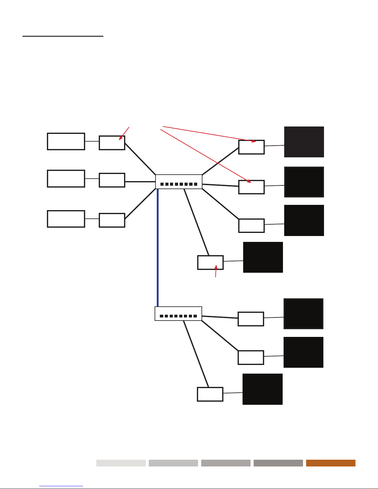
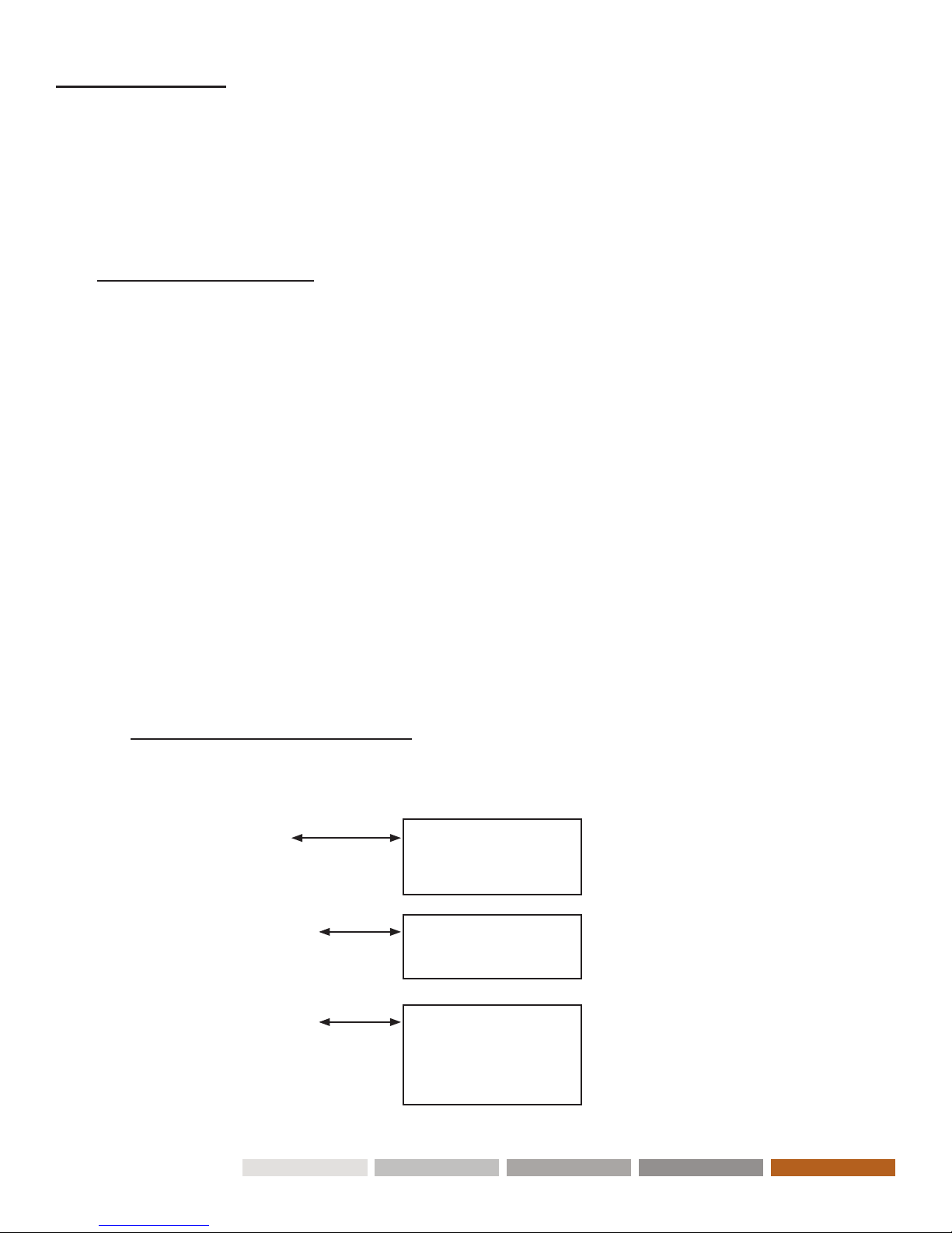
Installation as Matrix Multi-Channel Extender
(One to Many or Many to Many)
Supported Ethernet Switches
Cisco SG Series (SG300 or SG500) - Recommended
Cisco Catalyst 2960 Gigabit
Cisco Catalyst 3750 Gigabit
Dell PowerConnect 5400 Series (5424, 5448)
Dell PowerConnect 5500 Series (5524, 5524P, 5548, 5548P)
Dell PowerConnect 6200 Series (6224, 6224P, 6248, 6248P)
Netgear 7000 Series V2 (GSM7224, GSM7228PS, GSM7248, GSM7252PS)
Pakedge SW24-GBM, S24P
For a single- or multi-channel distribution system installation, an L2 Gigabit Managed Switch or
Gigabit Smart Switch that supports IGMP and Jumbo Frames (at least 8K) is required
Tx 1 Rx 1
Source 1 Display or
Monitor
Console
Rx 2
Display or
Monitor
Console
Rx 3
Display or
Monitor
Console
Tx 2
Source 2
Tx 3
Source 3
Gigabit Managed
Switch w/IGMP
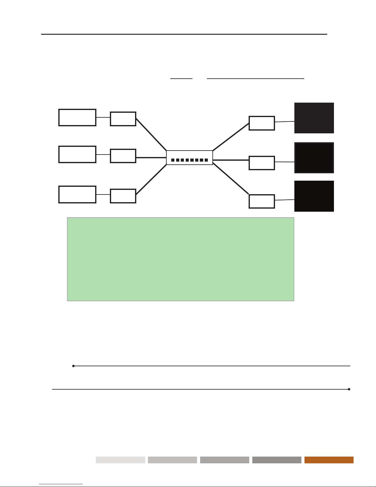
Conguring a Multi-Channel System
1. Power on the Gigabit Switch and enable Jumbo Frames (8k) and IGMP v2. IGMP Snooping should
be set for the Virtual Local Area Networks (VLAN) being used.
2. Set a unique Source channel on each Tx unit using the Channel rotary switches.
3. Set a default Receiver channel on each Rx unit using the Channel rotary switches.
Note:
e 16 channel IR remote control can be used to switch among dierent channels aer initial setup.
When a unit reboots, the default channel selected on the Channel rotary switch is used.
4. Connect all Tx and Rx units to the Gigabit switch via CAT-X cables or Fiber Optic cables. (See Fiber
Modules and Cables on page 25)
5. Connect all Tx with Sources, and all Rx with Display/TV HDMI/Console cables.
6. Optional: To control the source connected to the Tx, connect the IR emitter (transmitter) cable to
the Tx’s IR TX Jack, and point the IR emitter to the source’s IR input port you want to control.
7

7. Optional: Connect IR Receiver cable to the Rx unit’s IR RX Jack, and point toward the IR remote
control.
8. Optional: Connect RS-232 cable to Tx or Rx where RS- 232 controller or Display/TV/device can
take RS-232 command.
9. Optional: Connect USB cables to Tx/Rx for keyboard and mouse control or remote USB drives.
10. Plug-in DC power adapter to all Encoders and Decoders. Power units on.
11. Power on all Video Sources and start playing video.
12. Power on all displays and select HDMI or DVI input. All displays will show the source’s content
according to the channels set on Tx and Rx units.
Note:
You can switch channels shown on the display connected to the Rx using the channel switch (in blue
color), then press Apply button on Rx unit, or with the remote control included with the Rx unit.
13. Login to the web interface to further congure your multi-channel system.
( See Web Interface page 9 ).
8

Operation
All Tx and Rx units have a web interface to change settings and perform maintenance funtions. You
may need to adjust the default settings when using certain applications.
Some of these operations can be performed using the buttons on the units
Web Interface
To connect to the web interface, you can connect your laptop directly to an Tx/Rx using a CAT-X
cable, or follow this procedure to connect over the network for multi-channel setups:
1. Connect an Ethernet cable from a computer to the network on which the HDMX7 Tx or Rx unit is
connected.
2. Set the IP Address of your computer in the same IP subnet as the Tx and Rx units.
3. In a web browser, go to the IP address of the HDMX7 Tx or Rx unit accordingly.
You can nd the Tx/Rx IP addresses on the HDMX7 connected display using several methods:
(1) When video is displayed on the Rx unit:
Press the OSD button on the included remote control while the IR Receiver is connected to the
Rx unit. You will see the IP addresses of the Tx and Rx unit shown on the display.
(2) When no video is displayed:
Set the Rx rotary dial to an unused channel number and press the Apply button.
-Turn o the video input to the currently connected Tx unit.
-Look on the bottom right of the screen to see the IP addresses:
Transmitter: Local IP
Receiver: Remote IP
Web Interface Overview
e web interface has three tabs: System, Network and Functions
System Version Information
Update Frimware
Utilites
Network IP Setup
Device Mode
Functions Video over IP
USB over IP
Serial over IP
Extra Setting (Rx only)
9

Web Interface
System Tab
Displays HDMX7 version information, Upgrade Firmware and Utilities tools.
Version information
Update Firmware
Note:
• Make sure the Tx and Rx units to be updated are not processing audio or video during
the update. e update may fail and damage the devices.
• Do not power o the devices (Tx or Rx) during the update.
e rmware may not be fully loaded and the devices will not operate.
10

1. In the web interface, click Update Firmware.
2. Click Browse, then nd and select the rmware le, and click OK. Note that there are two dierent types of
rmware les: one for the Tx and one for the Rx unit. Please select accordingly.
3. Click Upload to upload the rmware le to the HDMX7 units.
4. e le upload to the HDMX7 device begins. Allow some time for the upload to begin. You will see the
progress screen display when HDMX7 starts writing the rmware to the device.
System Tab
Update Firmware
5. Aer the rmware is successfully written to the device, it will automatically reboot. When you see the Done:
Rebooting message, you can close the browser.
11

System Tab
Utilities
1. Reset to Factory Default
To reset the device back to the factory default settings, you can use the web interface, or
the Factory Default button on the device. e device will reboot aer the reset.
Note that the IP address will likely be changed aer the reset.
1) Reset unit via the web interface—just click the “Factory Default” button under Utilities.
2) Reset unit via hardware—physically press and hold the Factory Default button until Power and
Link LEDs are ashing. en, must power cycle the device.
2. Reboot the Tx or Rx device. Some setting changes require a reboot.
ere are two ways to reboot the Tx or Rx units:
1) Via the web interface—just click the “Reboot” button under Utilities.
2) Via hardware—physically press the Reset button on the unit.
3. Reset to the default EDID. Reset EDID is available only on the Tx unit.
Default EDID = 1920x1080 60fps, with 2 channel audio
To reset EDID, click the Reset EDID button
12

Web Interface
Network Tab
IP Setup
DHCP is the default IP Mode where the Tx or Rx unit address is assigned automatically. If your
network administrator connects a DHCP Server to the network, then the DHCP Server will assign the
IP addresses to each Tx or Rx units.
If a DHCP Server is not connected to the network (which is likely), then the Tx and Rx units will
automatically and dynamically self-assign Link Local IP addresses. ese addresses will be in a
special 169.254.xxx.yyy address range.
Link Local addresses are very convenient, require no conguration, and are a good
choice for small networks separate from the corporate network, but they have some limitations. ey
cannot be routed with an outside network, and they can be changed when the device is rebooted or
when the rmware is updated.
You can see these automatically assigned addresses (DHCP or Link-Local) on the monitor or TV con-
nected to the Rx unit.
13

Alternatively, you can assign a Static IP address to each Tx and Rx units. Contact your network
administrator for these addresses. is is more work to congure, but these addresses will be permanent
and can be connected to a larger network.
In the web interface, the default IP address and subnet mask show automatically. In Extender Mode, the
Tx and Rx units are in an one-to-one conguration that does not need to connect to an Ethernet switch.
You do not need to change these settings (DHCP IP mode is recommended).
In Matrix Mode, the the Tx and Rx units are connected to a Gigabit Ethernet switch that requires
network conguration for good performance. Jumbo Frames (8k) and IGMP v2 should be enabled.
IGMP Snooping should be set for the VLAN(s) being used.
If you are unfamiliar with IP addressing and networking, contact your network administrator or
network vendor for help with the conguration.
Note:
Currently, only IPv4, IP address is supported. No IPv6 address.
Network Tab
Device Mode
HDMX7 can be used in two modes: Extender Mode and Matrix Mode.
Most changes in the Device Mode setting require a reboot of each Transmitter and Receiver
unit for the new setting to take eect.
Note:
e IP address of the device may change aer a reboot if using link-local addresses.
Extender Mode:
Extender Mode is used when one Tx is connected point-to-point to a single Rx unit.
You can tell your network administrator that Unicast addressing is used, which all networks support.
Matrix Mode:
Matrix Mode is used in all other AV congurations when there are more than two Tx and Rx. is uses
the Multicast IP networking protocols to eciently transmit video to multiple Rx units. If you are
using an existing network or a network using multiple switches and/or routers, you should tell your
network administrator that Multicast addressing is being used. e administrator may have to do
some network conguration to support Multicast, that is IGMP protocols. VLANs can also be used to
segregate AV trac and to increase performance.
Static IP Mode
14

Function Tab of Tx (Transmitter)
e settings dier slightly in the Tx and Rx web interfaces.
Video over IP → Video Quality
Graphic Mode vs Video Mode
e default Video Quality is set to Video Mode which is best for movies and videos.
If the singal is a static, graphical source, such as an image, pattern generator or text,
then Graphic Mode should be selected to maintan the sharper image.
Video over IP → Anti-Dither
Anti-Dithering Mode is designed to work with certain AMD graphic cards that provide dithering
output. Dithering output is used to make color look better than its original color depth. is presents
diculty for Video Compression to maintain low bandwidth.
Currently, Dithering Output is only required with AMD graphic cards.
HDMX7 provides Anti-dithering for 1 bit, 2 bit, or o.
Don’t enable this mode unless it is specically required.
15

Function Tab of Rx (Receiver)
Automatically Copy EDID from this Receiver Video Output
HDMX7 features EDID Management. Before the source can send video and audio data, the source
device connected to each Tx unit reads the EDID for the display connected to each Rx unit. e EDID
contains information about what type of audio and video data can be accepted from the source.
By default, the default HDMI EDID stored in the Tx unit is used. e EDID from the Rx unit’s HDMI
output connected device, such as display, amplier, and so on, can be copied and stored in the Tx unit
16

Extra Settings (On the Rx unit’s web interface only)
DPMS is a standard for monitor power saving. e default setting is No (o). When the DPMS
setting is o, and there is no input from the Tx unit, the Rx unit will show “Waiting for video
source - standby” on the bottom le of the display.
When DPMS is on (Yes) and there is no video output from the Tx, the Rx will not output video.
is will generally put the display into sleep mode. Turning o the source video connected to
the Tx unit will cause the remote displays connected to the Rx unit to go to sleep. When the
video signal are turned back on, the monitors will wake and display the video.
To enable or disable DPMS:
1. In the Rx web interface, choose Functions → Extra Settings → Enable DPMS.
2. Click Ye s or No, then click Apply.
17
is enables support for multi-channel audio and 3D functions from the device connected to the Rx unit.
If enabled by the HDMX7 web interface, from the device connected to the Rx unit the EDID can be copied
automatically every time the video channel is switched.
ere two dierents ways to copy the EDID
1. Physically push the EDID Copy button to establish Tx and Rx unit’s communication
1) Unplug the HDMI/DVI cable from the Tx
2) Unplug the power supply from the Rx unit, then press the Copy EDID button on the Rx unit
3) Power on the Rx unit and long-press while booting until the Power LED starts blinking
4) Plug the HDMI/DVI cable back into the Tx unit
2. Use the Web Interface to Automatically Copy the EDID when Channels are Switched:
1) Login to the Rx unit’s web interface
2) In the Functions tab, select the Automatically Copy EDID from this Receiver Video Output
3) Click “Apply” button
4) Reboot the Rx unit.
Enable DPMS for Monitor PowerSaving
e Enable Channel OSD setting allows you to show or hide the channel number on the display
screen while switching channels. (see Page 20, Channel OSD picture)
1. In the Rx web interface, choose Functions → Extra Settings → Enable Channel OSD.
2. Click On or O, then click Apply.
Enable Channel OSD

USB Extending and Controls
On the Rx unit, there are three USB 2.0 ports, and one USB 1.1 port, which should be used for low-
speed USB devices such as a keyboard.
USB 1.1 for HID
In Extender mode
Only a single Rx unit will be able to communicate with a Tx unit. However, multiple USB devices can
be connected to Rx unit.
In Matrix mode
e USB host devices can only be controlled from one Rx unit at the same time. If the USB LED is not
lit orange, press the Select USB button (on the Rx unit) to acquire USB control.
Connecting multiple mouse/keyboard devices to each Rx unit makes little sense if multiple users are
attempting to control the same computer. However, if the dierent USB devices are connected, only
one Rx unit can use USB devices without interference.
Enable or disable USB control in the web interface in Functions → Enable USB over IP.
For A/V type devices without USB control, you should disable USB to improve switching time.
18

Audio Input and Output (Extending and Monitoring)
1. A computer typically has a Mic In jack, as part of its sound card. To access this jack from the Rx
unit, connect the microphone to the pink IN jack on the Rx unit.
2. To get the audio from the microphone into the computer, connect a 3.5mm-to-3.5mm stereo cable
from the pink Line out jack on the Tx unit to the Line in jack on the computer.
Warning: DO NOT connect the cable from the Line out jack on the Tx unit to the
Mic In jack on the computer. Doing so will result in audio “clipping” and may cause
damage to the sound card.
Note:
HDMI audio is passed through to the HDMI Out connector on the Rx unit.
However, if a 3.5mm stereo cable is connected from a computer to the green Line In jack
on the Tx unit, the embedded HDMI audio is switched o. is allows the audio signal from
Line In jack (Tx unit) to be received on the green Line Out jack (Rx unit)
Using a Microphone
e audio behavior diers between under Extender Mode and under Matrix Mode
Under Extender Mode
A separate microphone can be connected to the Rx unit. e audio signal coming from
the microphone will be sent to the Tx unit on the same channel as the Rx unit.
Under Maxtix Mode
e Mic In jack is disabled in multicast mode. If an audio source is connected to the Line In
jack on an Tx unit, the audio signal will be distributed to all Rx units set to the same channel.
Each Rx unit should have a separate pair of powered speakers connected to its Line Out jack.
19
This manual suits for next models
1
Table of contents
Other Connect Pro Extender manuals
Popular Extender manuals by other brands

Devolo
Devolo Audio Extender supplementary guide

Patton electronics
Patton electronics 2173R user manual

ATEN
ATEN CE750A Quick start up guide

Gefen
Gefen ToolBox GTB-DPKVM-3CAT7 user manual

T.I.P.
T.I.P. HWW 4400 INOX Plus Translation of original operating instructions

Analog way
Analog way EXT-DP12-OPT quick start guide

NVT Phybridge
NVT Phybridge EC-Base Quick install guide

Stuart Turner
Stuart Turner Mainboost MB 100SV Installation, operation & maintenance instructions

Sinovision
Sinovision HDE01X user manual

Broadata
Broadata LBC-H2CS-T/R-Lite user manual

StarTech.com
StarTech.com 8STSV565DUTPU manual

Extron electronics
Extron electronics DTP T UWP 4K 232 D Setup guide