Connect Tech BlueStorm/Express User Manual
Revision 0.18
Table of Contents
Customer Support Overview .......................................................................................................................... 4
Contact Information........................................................................................................................................ 4
Limited Lifetime Warranty............................................................................................................................. 5
Copyright Notice ............................................................................................................................................ 5
Trademark Acknowledgment ......................................................................................................................... 5
Introduction .................................................................................................................................................... 6
Features .......................................................................................................................................................... 6
BlueStorm/Express Diagrams......................................................................................................................... 7
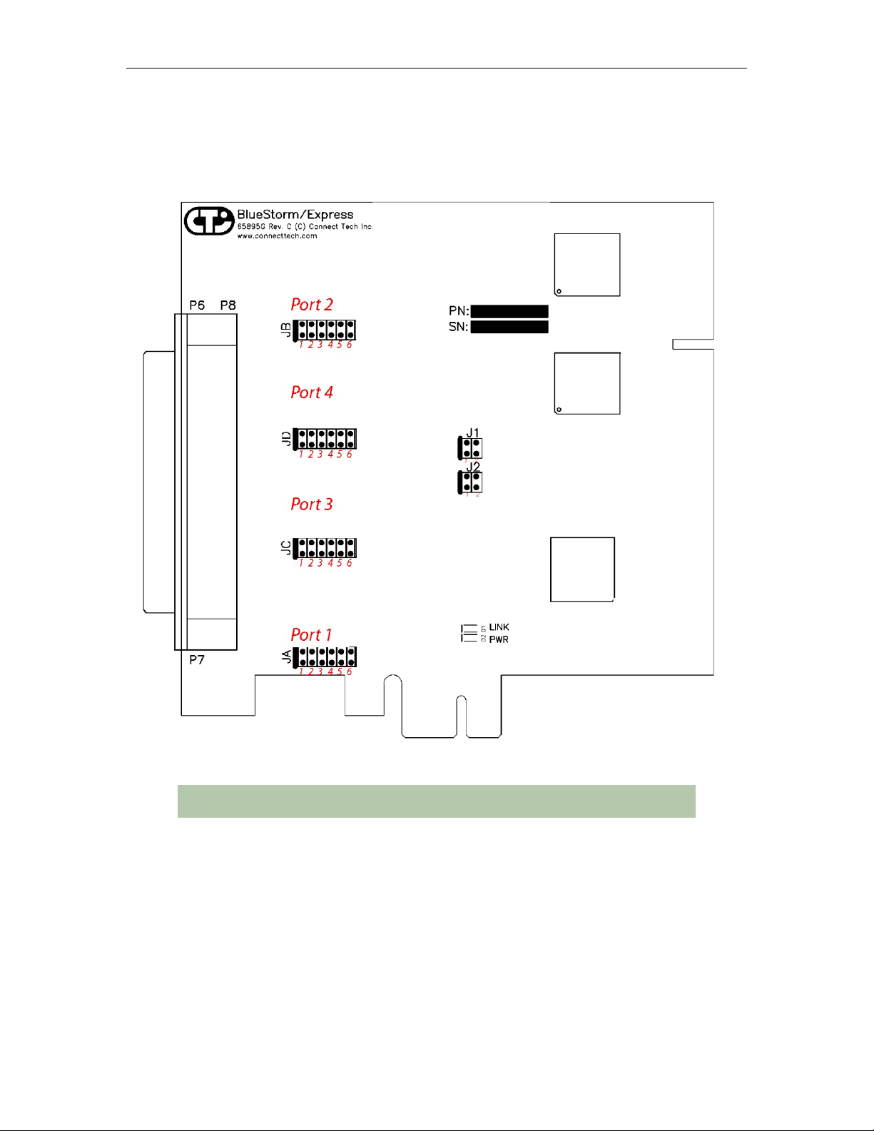
Figure 1: BlueStorm/Express RS-232/422/485 two and four port model hardware components
(BEG001, BEG002, BEG003, BEG004, BEG012, BEG013)................................................................................... 7
Figure 2: BlueStorm/Express RS-232/422/485 8 and 16 port model hardware components (BEG005, BEG006) ... 8
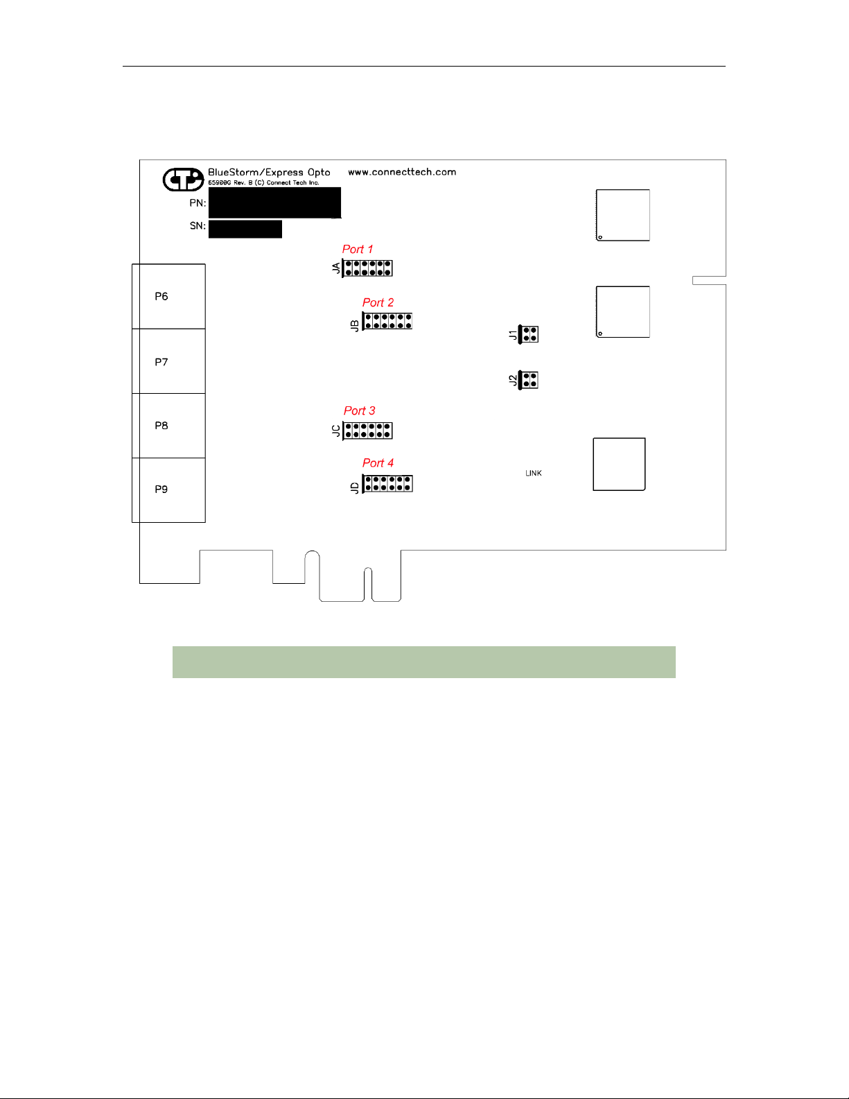
Figure 3: BlueStorm/Express Opto RS-232/422/485 four port model hardware components (BBG001)................ 9
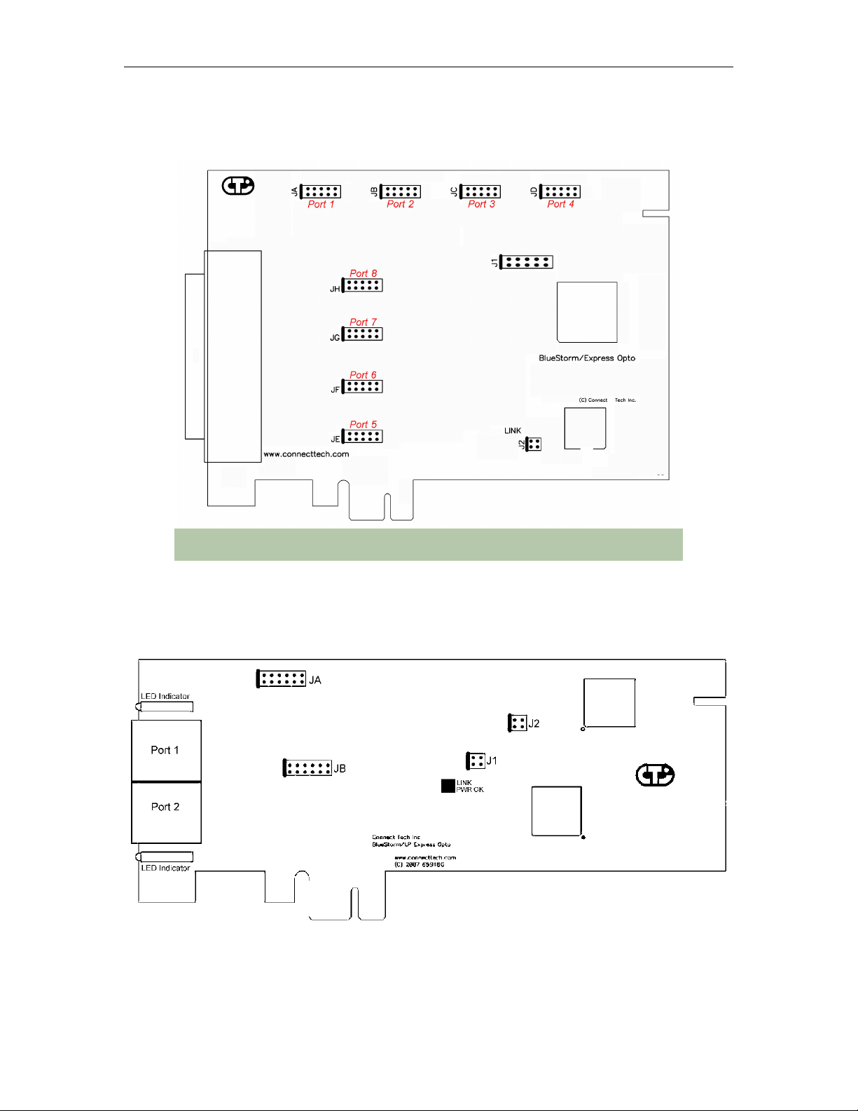
Figure 4: BlueStorm/Express Opto (1 kV) RS-232/422/485 eight port model hardware components (BBG003) .. 10
Figure 5: BlueStorm/Express LP Opto RS232/422/485 two port model hardware components (BCG001) ........... 10
Figure 6: BlueStorm/Express LP 8-Port RS232/422/485 hardware components (BFG001/BFG002) .................... 11
Figure 7: BlueStorm/Express Isolated 8-Port RS232 hardware components (BDG001) ........................................ 11
Figure 8: BlueStorm/Express Isolated 4-Port RS232/422/485 Low Profile (BCG004) .......................................... 12
BlueStorm/Express Installation Overview ....................................................................................................13
Hardware Configuration................................................................................................................................13
Interrupts and Memory Address Selection.............................................................................................................. 13
Electrical Interfaces.......................................................................................................................................13
RS-232 Electrical Interface ..................................................................................................................................... 13
RS-422/485 Electrical Interface.............................................................................................................................. 13
Full Duplex Mode ............................................................................................................................................13
Half Duplex Mode ...........................................................................................................................................14
Multi-drop Mode..............................................................................................................................................14
Line Bias/Termination .....................................................................................................................................14
Jumper Block Settings ............................................................................................................................................ 14
Figure 8: Example of various port configuration jumper block settings ................................................................. 14
Tri-state Operation .................................................................................................................................................. 15
BCG004 and BBG008: BlueStorm/Express, Isolated ...................................................................................16
Connector Pinouts .........................................................................................................................................17
Table 1: DB-9 Male Pinouts - TYPE A ...................................................................................................................17
Table 2: RJ-45 Pinouts – TYPE B ...........................................................................................................................17
Table 3: DB-9 Male Pinouts - TYPE B....................................................................................................................18
Table 4: DB-9 Male Pinouts - TYPE C....................................................................................................................18
Table 5: DB-37 ........................................................................................................................................................19
Table 6: VHDCI-68 .................................................................................................................................................20
Table 7: HDB-78 (BBG003)....................................................................................................................................22
Table 8: HDB-78 (BBG008)....................................................................................................................................24
Table 9: HDB-62 Connector Pinout.........................................................................................................................26
Table 10: HDB-44 (BCG004)..................................................................................................................................28
RS-422/485 Recommended Wiring...............................................................................................................29
Type “A” RS-422/485 Wiring ................................................................................................................................ 29
Type “B” RS-422/485 Wiring................................................................................................................................. 29
Hardware Installation ....................................................................................................................................30
Installing the BlueStorm/Express into Your System............................................................................................... 30
Software Installation......................................................................................................................................30
Software First Installation (Windows) .................................................................................................................... 31
Hardware First Installation (Windows)................................................................................................................... 31
Port Settings............................................................................................................................................................ 32
Advanced Port Settings........................................................................................................................................... 33
Use FIFO Buffers.............................................................................................................................................33
Receive and Transmit FIFO Settings ...............................................................................................................33
Software Settings for RS-422/485........................................................................................................................... 33
Baud Rate Mapping .........................................................................................................................................34
Clock Frequency ..............................................................................................................................................34
COM Number ..................................................................................................................................................34
Specifications ................................................................................................................................................35