AZZA 6IL User manual

PT-6IL
MAINBOARD
( VER. 1.x )
USER’S MANUAL

PT-6IL MAINBOARD TABLE OF CONTENTS
i
TABLE OF CONTENTS
Chapter & Section Page
1 INTRODUCTION ............................................................................................. 1
1.1 OVERVIEW................................................................................................... 1
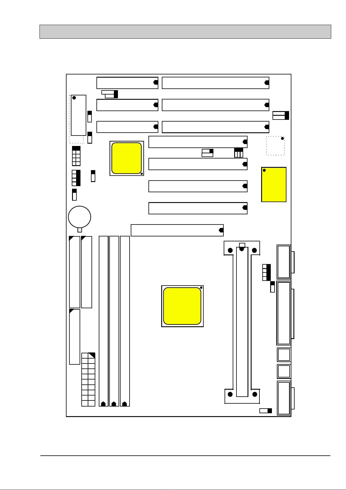
1.2 PT-6IL VER. 1.X MAINBOARD LAYOUT ............................................ 2
1.3 SPECIFICATIONS ....................................................................................... 3
2 INSTALLATION ................................................................................................ 1
2.1 UNPACKING................................................................................................. 1
2.2 POWER ON THE PC SYSTEM................................................................ 1
2.3 POWER OFF THE PC SYSTEM............................................................... 5
3 HARDWARE SETUP........................................................................................ 1
3.1 INSTALLATION OF CPU........................................................................... 1
3.1.1 BOXED PENTIUM II CPU .................................................................... 2
3.1.2 OEM PENTIUM II CPU......................................................................... 2
3.2 RETENTION MECHANISM AND HEAT SINK SUPPORT............. 4
3.3 INSTALLING RETENTION MECHANISM KIT................................. 5
3.4 INSTALL THE BOXED PENTIUM™ II PROCESSOR ......................6
3.5 REMOVING BOXED PENTIUM™ II PROCESSOR .......................... 10
3.6 INSTALLING OEM PENTIUM™ II PROCESSOR........................... 12
3.7 REMOVING OEM PENTIUM™ II PROCESSOR ............................. 14
3.8 INSTALLING DRAM................................................................................ 14
3.9 CONNECTORS ........................................................................................... 18
3.10JUMPERS .................................................................................................... 33
4 AWARD BIOS SETUP..................................................................................... 4-1
4.1 GETTING STARTED.................................................................................. 1
4.2 MAIN MENU................................................................................................ 2
4.3 CONTROL KEYS ........................................................................................ 2
4.4 STANDARD CMOS SETUP ...................................................................... 3
4.5 BIOS FEATURES SETUP ......................................................................... 4
4.6 CHIPSET FEATURES SETUP ................................................................. 6
4.7 POWER MANAGEMENT SETUP ........................................................... 8
4.8 INTEGRATED PERIPHERALS.............................................................. 10
4.9 PNP/PCI CONFIGURATION .................................................................. 12
4.10 LOAD SETUP DEFAULTS ................................................................... 15
4.11 SUPERVISOR PASSWORD / USER PASSWORD .......................... 17
4.12 IDE HDD AUTO DETECTION............................................................ 17
4.13 SAVE & EXIT SETUP........................................................................... 18
4.14 EXIT WITHOUT SAVING.................................................................... 20

PT-6IL MAINBOARD INTRODUCTION
ii
SOMETHING IMPORTANT !
¶TRADEMARKS
All trademarks used in this manual are the property of their respective owners.
¶LOAD SETUP DEFAULTS
“LOAD SETUP DEFAULTS” is the function which will have the BIOS default
settings loaded into the CMOS memory, these default settings are the best-case
values that should optimize system performance and increase system stability .This
function will be necessitated when you receive this mainboard, or when the system
CMOS data is corrupted. Please refer to the page 5-12 for executing procedures.
¶DISCHARAGE CMOS DATA
Whenever you want to discharage the CMOS data or open the system chassis, Make
sure to disconnect the AC power first because there is always the 5V standby voltage
connected to the ATX form-factor mainboard. Without disconnecting the AC power
connector from the PC system, the mainboard may be damaged by any incorrect
action . Please refer to the page 4-16 for executing procedures.
¶WAKE ON LAN
In order to support the Wake On LAN feature, the system requires a special SPS
(switching power supply), Such power supply must be able to provide at least 700
mA of driving capability on the “5V standby” voltage. Please refer to the page 4-12
for pin asignment.
¶WARNING !
The "Static Electricity" may cause damage to the components on the mainboard, In
order to avoide the damage to the mainboard accidentally, please discharge all static
electricity from your body before touching this mainboard.
¶NOTICE
Information presented in this manual has been carefully checked for reliability;
however, no responsibility is assumed for inaccuracies. The information contained in
this manual is subject to change without notice.

PT-6IL MAINBOARD INTRODUCTION
1
I. INTRODUCTION
A. OVERVIEW
ThePT-6ILis a high performance personal computer mainboard designed for the
Pentium™ II processor. PT-6IL is an ATX form-factor mainboard with A.G.P.
(Accelerated Graphics Port) and PCI Local Bus on board. It is designed based on the
Intel® 82440LX AGPset™ system chipset and Winbond® I/O chipset, built-in two
channel “PIO” and “Ultra DMA/33 Bus Master” mode PCI IDE ports, one Floppy Disk
control port, two high speed Serial ports (UARTs) and one multi-mode Parallel port and
supports PS/2™ mouse, IR and USB ports. It is designed to fit a high performance
Pentium™ II (S.E.C. Cartridge) processor 233 MHz, 266 MHz , 300 MHz and 333MHz
based solution for high-end and true GREEN-PC computer systems.
The Pentium™ II Processor is a 64-bit processor with RISC technology, which offers
several key features such as built-in 256KB/512KB L2 cache, 12-stage superpipeline
architecture, out of order execution .... etc. In order to optimize of its capabilities and
performances, the 32-bit Operating System (such as Windows® NT and OS/2™) and
32-bit application are recommended.
The Accelerated Graphics Port (A.G.P.) on the PT-6IL mainboard is designed for AGP
3D video display card. Unlike PCI-based display cards, the AGP technology provides
lightning data throughput to fully facilitate the 3-Dimensional and multimedia graphics
display. The data transfer rate on AGP can be up to 133Mhz and which is much faster
than the traditional 33MHz PCI VGA card.
The AGP is a new video display technology and it requires device driver or new
Operating System to enable this accelerated graphic feature. Windows® 98 supports
AGP directly but Windows® 95 still need the appropriate device drivers to support
AGP feature. Please don’t worry about the device driver, because you can always find
the device driver included in the AGP card. Regarding the definition of AGP interface
and its functionality, please refer to the latest A.G.P. Interface Specification. which can
be found at the Intel web site, the URL is “developer.intel.com/technology/agp”

PT-6IL MAINBOARD INTRODUCTION
2
A. PT-6IL VER. 1.X MAINBOARD LAYOUT
intel
82371AB
SPKR
KBLOCK
HL
SL
PW
RS
Winbond
W83977TF
SL3
USB2
USB1
SL2
SL1
PCI 1
PCI 2
PCI 3
JP3
JP2
CN3
POWER CON.
CN15
CN16
CN11 COM B CN2 COM A
CN4
PS/2
MS.
PS/2
KB.
CN1
DIMM 3
CN8
CN5CN7 LPT
CN9 IDE2
CN10 IDE1 CN6 FDC
JP9
BAT1
+
PCI 4
AGP
_
DIMM 2
DIMM 1
CN12
JP5
CN17 IR/FIR
CIR
CN13
SB-LINK
82443LX
intel
JP1
JP4
SLOT1
J1
J2
CN14
JP8
JP7
JP6
LM78/
LM79
SYS. BIOS

PT-6IL MAINBOARD INTRODUCTION
3
A. SPECIFICATIONS
¥CPU
Intel® Pentium™ II and Deschutes (S.E.C. Cartridge) processor 233 MHz, 266
MHz, 300 MHz and up to 333MHz.
¥CPU VCC
Three Voltage Regulator circuits on board, supports +1.80V DC through +3.5V DC
CPU Core Voltage and all lower-voltage components.
Note : The CPU Core Voltage will be Detected and adjusted automatically by the
VID-pin on the CPU, so there is no manual-adjustment required to select the CPU
voltage. Simply plug in the CPU and start immediately.
¥WORD SIZE
Data Path : 8-bit, 16-bit, 32-bit, 64-bit
Address Path : 32-bit
¥PC SYSTEM CHIPSET
Intel® 82440LX AGPset™ (82443LX, 82371AB)
¥SUPER I/O CHIPSET
Winbond® W83977TF/W83977ATF (optional)
¥BUS FREQUENCY
66 MHz fixed
¥MEMORY
DRAM : Three 168-pin DIMM sockets are designed onboard which support 8, 16,
32,64 or 128MB 3.3V Un-buffered EDO and SDRAM DIMM modules. Maximum
memory size can be upto 384 MB with Parity / ECC (Error Checking and
Correcting) supported.
CACHE:512KB pipelined burst SRAM built-in Pentium™ II or Deschutes
processor.
¥BIOS
AWARD System BIOS. 128KB x 8 Flash ROM
(Supports Plug & Play, ACPI, DMI and Green functions).

PT-6IL MAINBOARD INTRODUCTION
4
¥EXPANSION SLOTS
AGP Slots : 32-bit x 1 (Supports 1x or 2x AGP graphics cards)
PCI Slots : 32-bit x 4 (All Master/Slave, PCI 2.1 Compliant)
ISA Slots : 16-bit x 3 (One of the slot is PCI/ISA shared)
¥WOL PORTS
One WOL connector supports Wake-On-LAN (WOL up-designed)
¥SB-LINK PORTS
One SB-LINK feature connector to support PCI sound cards. (such as Creative™
Labs EMU8008 sound chip)
¥USB PORTS
Two Universal Serial Bus (USB) ports. (5-pin for each port)
¥IDE PORTS
Two channels of Ultra DMA/33 Bus Master IDE ports, which will support up to 4
IDE devices like IDE hard disk, ATAPI CD-ROM and LS-120/ZIP-100 devices.
The IDE ports can be programmed to support PIO Mode 4, DMA mode 2 and Ultra
DMA/33.
¥SUPER I/O PORTS
1.Two high speed NS16C550 compatible serial ports (UARTs).
2.One parallel port, supports SPP/EPP/ECP mode.
3.One Floppy Disk Control port.
¥IR PORT
One HPSIR and ASKIR compatible IR transmission connector (5-pin).
One Consumer IR transmission connector (4-pin, optional).
¥MOUSE AND KEYBOARD
One PS/2™ mouse connector, One PS/2™ keyboard connector.

PT-6IL MAINBOARD INTRODUCTION
5
¥HARDWARE MONITORING (optional)
LM78 or LM79 is designed on the board to monitor hardware healthy status like
system voltages, system temperature, and three cooling fan speed. When the CPU is
over heated, the system speaker will gives beeping alarm to so that you can take
proper action to prevent damage to your system. When you hear the beeping alarm,
be sure to turn the power off and open the chassis immediately, check on the
cooling fans (especially the CPU cooling fan ) to see whether it is working properly
or not. If you don’t know how to handle it, send the PC system to your dealer for
technical support.
¥ACPI
Advanced Configuration and Power Interface (ACPI) function is strongly
recommended by PC‘98: Followings are the ACPI features designed on the board:
1.On Now: power on the system by panel-switch, Keyboard, PS/2™ Mouse,
Modem ring-in, RTC alarm or LAN signal.
2.Power off (soft-off) by OS or Panel-switch.
3.CPU cooling fan auto-off during Suspend state.
4.Resuming of PC system. (such as Modem ring-in, RTC alarm, .... etc.)
5.Supports Full-On/Doze/Standby/Suspend operating modes.
¥JUMPER FREE
In order to provide a most convenient way to help users to install the CPU onto the
mainboard, PT-6IL has the Jumper-free feature designed on the board, There is no
“jumper setting” required to select the CPU speed and CPU Core voltage. (CPU
speed is selected by CMOS setup, please refer to page 4-7 for details )
¥DIMENSION
1.Width & Length : 305 mm x 186 mm.
2.Height : 2 1/2 inches with CPU Retention Mechanism.
3.PCB Thickness : 4 layers, 0.05 inches normal.
4.Weight : 18 ounces.
¥ENVIRONMENT LIMIT
1.Operating Temperature : 10to 40. (50to 104)
2.Required Airflow : 50 linear feet per minute across CPU.
3.Storage Temperature: - 40to 70. (- 40to 158)
4.Humidity : 0 to 90% non-condensing.
5.Altitude : 0 to 10,000 feet.

PT-6IL MAINBOARD INSTALLATION
1
I. INSTALLATION
A. UNPACKING
The mainboard contains the following components in the package. Please inspect the
following contents and confirm that everything is there in the package. If anything is
missing or damaged, call your supplier for instructions before proceeding.
lOne PT-6IL mainboard.
lOne USER‘S MANUAL.
lOne Cable set for IDE and Floppy devices.
lOne Pentium™ II Processor Retention Mechanism (RM).
lOne CD diskette for IDE Bus Master Drivers and Virtual Drive programs.
The PT-6IL mainboard contains electrostatic sensitive components and it can be easily
damaged by static electricity. So please leave it sealed in the original packing until
when installing.
A grounded anti-static mat is recommended when unpacking and installation. Please
also attached an anti static wristband to your wrist and have it grounded to the same
point as the anti-static mat.
After the opening of the mainboard carton, please observe the mainboard carefully to
make sure there is no shipping and handling damage before you can install the
mainboard to the system.
Having finished all the procedures above, you are now ready to install the mainboard to
the chassis. Please make sure that the chassis is the ATX type so that the mounting hole
will match with the PT-6IL mainboard.
A. POWER ON THE PC SYSTEM
When the PT-6IL mainboard has been assembled in a system successfully , there are
several ways to power on the system. Please read the following description for all the
details.

PT-6IL MAINBOARD INSTALLATION
2
¨POWER BUTTON
The power button can be programmed by COM setup program and it has different
features. Please refer to page 3-28 for detail function description.
Note: This power button can not be used to power-on the PC system if the
”Password“ is selected to power on your system. (please refer to page 4-10 for the
“INTEGRATED PERIPHERALS“ in the CMOS setup.) However, you can
always use the power button to turn off the power.
¨KEYBOARD (PASSWORD OR HOT KEY)
It is a nightmare when someone uses your PC system without your permission and
destroys all the valuable data stored in the system. Now the problem can be avoided
by using the PT-6IL mainboard. PT-6IL allows you to enter your personal password
or a combination of hot key to power on your system. When the system power is off,
PT-6IL still keeps scanning the keyboard status waiting for the correct password or
hot key input to turn on the system power. Without the correct password or hot key,
no one else can turn on the PC system ( neither by the power button ). So the PC
system is secured for you. There are two ways to power-on the PC system by
keyboard, they are “Password” and “Hot KEY”. Please refer to page 4-11 for the
BIOS setting.
When the “Password” and “Hot KEY” is selected, you will have to reboot the PC
system to activate the setting, when you see the POST (Power On Self Test) is
completed, the setting is changed and stored in the CMOS memory. Having finished
the procedure, you may use the keyboard to power-on the PC system afterward.
In case that you forget the “Password” or “Hot Key”, disconnect the AC power for
30-60 seconds then re-connect the AC power to the PC system, the power button will
be activated again and you can use the power button to turn on the system. Input
your personal password in the BIOS setup again, and then you may use the new
password to power-on the PC system afterward.
¨PS/2™ MOUSE (MOUSE LEFT OR MOUSE RIGHT BUTTON)
When you are tired of pressing on the power button or keying in the password to turn
on the PC system, there is another extremely convenient way for you.

PT-6IL MAINBOARD INSTALLATION
3
When you have a PS/2™ mouse connected to the system, you may change the setup
in the BIOS and use the mouse click to turn on the PC system power. It is so simple,
convenient and welcomed by children. Please refer to page 4-101 and page 4-11 for
the BIOS settings
To use the mouse key to turn on the PC system power, the mouse click must be
done quickly and continually. Basically, 2-5 quick clicks on the mouse key will turn
the power immediately.
In order to activate the mouse key feature, you will have to reboot the PC system
after the BIOS setting and wait until the POST (Power On Self Test) is completed.
Having finished the procedure, you may use the mouse key to power-on the PC
system afterward..
Note: This feature is not available on the COM (serial) port mouse.
¨RTC ALARM
PC system can be waked up by the RTC setting in the CMOS. You can set the
alarming date and time in the RTC memory, When RTC alarms, the PC system will
be triggered and wakes up automatically.
Enable the “Resume by Alarm” selection in the BIOS setup utility, and then input
the accurate date and time in following fields. (the “Resume by Alarm” is located in
the “POWER MANAGEMENT SETUP”, please refer to page 4-8 and page 4-9 for
detail procedures), Having stored the RTC alarm setting, the PC system will be
turned on automatically according to the date and time which is recorded in the
CMOS memory.
Same as the above, you have to reboot the PC system and wait for the POST (Power
On Self Test) is completed to enable the RTC alarm.
¨MODEM RING-IN
Everyone knows that a PC system can be used as a fax machine to send or receive
fax messages. But most people still use fax machine to receive their messages
because it is not practical to have the system powered on all day long waiting for the
incoming messages. Now the problem can be solved by using the PT-6IL
mainboard. PT-6IL can be triggered by a modem ring-in signal. When you have a
external modem installed, you can leave the PC system power off. Whenever there

PT-6IL MAINBOARD INSTALLATION
4
is the incoming message, the PC system will be triggered by the ring-in signal and
wake up automatically to receive the message for you. From now on, you can tell
your PC system to receive the fax message for you.
In order to use the ring-in signal to wake up your PC system, you will have to use the
EXTERNAL MODEM and have it connected to one of the SERIAL PORTS
( COMA or COM B ). When the system power is off, PT-6IL will continue to detect
the serial port status. When it detects the ring-in signal, the system power will be
turned on and start to receive the incoming messages automatically. ( you may need
to have the software like Award Zero-Volt Data-Suspend Utility so that you can use
the fax utility to receive the incoming fax message ).
To enable the Modem Ring-In feature, you will have to use the BIOS setup utility
and enable the “Resume by Ring or LAN” option (it is located in the “POWER
MANAGEMENT SETUP”, please refer to page 4-8 and page 4-9 for the settings).
Having completed the BIOS setup, you have to reboot the PC system so that BIOS
can verify the setting. ( the “DMI pool data” will be verified by the BIOS when
loading the operating system). Simply speaking, shut down the PC system and
reboot the system. The modem ring-in feature will be enabled when the operation
system has been loaded.
Note: This function is unavailable when using the internal MODEM card.
¨WAKE ON LAN ( WOL )
There is a WOL connector (CN14, please refer to page 3-24 for the pin assignment
of WOL connector) on the mainboard which is designed onboard to connect to the
signal from a LAN card that supports a Wake On LAN feature. When such LAN
card is installed, you may turn on the PC system from your remote server and
monitor the PC status.
To enable this feature, you will have to use the BIOS setup utility to enable the
“Resume by Ring or LAN” (it is located at “POWER MANAGEMENT SETUP”,
please refer to page 4-8 and page 4-9 for the settings). Having completed the BIOS
setup, you have to reboot the PC system so that BIOS can verify the setting. ( the
“DMI pool data” will be verified by the BIOS when loading the operating system).
Simply speaking, reboot the PC system, the Wake On LAN feature will be enabled
when the operation system has been loaded

PT-6IL MAINBOARD INSTALLATION
5
Note: This function will be disabled if you turn off the power before the system can
verify the DMI pool data.
A. POWER OFF THE PC SYSTEM
There are two ways to power off the system. They are “Shut Down by Power Button”
(please refer to page 3-28 for details) and “ Shut Down by OS”. (such as Windows® 95
and Windows® 98, you can choose the Shut Down from the file menu and the system
will be powered off immidiately ).

PT-6IL MAINBOARD HARDWARE SETUP
1
I. HARDWARE SETUP
Before you can start to install this mainboard, some hardware settings is required to
make sure it will work perfectly in your PC system. To configure the PT-6IL mainboard
is a simple task, only a few jumpers, connectors, cables and sockets needs to be selected
and configured. (For the detailed locations of each component please refer to page 1-2 “
mainboard layout” )
A. INSTALLATION OF CPU
PT-6IL provides a jumper-free design on the board. When you have installed the
Pentium™ II processor onto the mainboard, PT-6IL will detect the CPU type and decide
the proper CPU voltage automatically. So you don’t have to make any jumper setting to
select the CPU voltage. All you have to do is use the BIOS setup program to select the
speed of CPU clock.
The socket where we are going to plug in the CPU is the slot type connector ( J1 ). This
slot is designed for Pentium ™ II processor and we call it – the SLOT 1.
Basically, Slot 1 is a new technology and it is totally different to the traditional Pentium
CPU socket – Socket 7. Because Slot 1 is a revolutionary new architecture and the
installation of Pentium™ II processor need some additional skill. The following
sections will show you how to install the CPU support kit and install the Pentium™ II
processor onto the mainboard.
There are two types of Pentium ™ II CPU - the boxed Pentium™ II processor and OEM
Pentium™ II processor. These two different packages are different and they have
different accessories. So when installing different type of CPU, the installation
procedure will be different.
The boxed Pentium™ II processor is for retail purpose and it can be purchased from the
retail store. As for the OEM Pentium™ II processor, it is for OEM customers like
system integrators when they are assembling the PC system. Sometimes, users will see
the OEM Pentium™ II processor sold in the retail store. So this manual will have the
installation procedures for both of the two processors included.

PT-6IL MAINBOARD HARDWARE SETUP
2
Basically, the core logic of boxed Pentium™ II processor and OEM Pentium™ II
processor are identical, The major difference between these two processors is the boxed
CPU has head sink, cooling fan and heat sink supporter, while the OEM Pentium™ II
CPU doesn’t. Please look at following pictures for the difference:
1. Boxed Pentium II CPU
Boxed Pentium CPU Boxed Pentium CPU
Side view one Side view two
Figure 3-1 Boxed Pentium™ II CPU

PT-6IL MAINBOARD HARDWARE SETUP
3

PT-6IL MAINBOARD HARDWARE SETUP
4
1. OEM Pentium II CPU
A. RETENTION MECHANISM AND HEAT SINK SUPPORT
When Installing the Pentium™ II Processor ( both boxed and OEM ), you will need a
Retention Mechanism (RM) kit and a Heat Sink Support kit so that Pentium™ II
processor and heat sink can be fixed and seated firmly on mainboard. The RM kit
includes 2 parts (RM and RMAM) you will find them provided in the PT-6IL package.
The Boxed Pentium™ II Processor:
You will need a RM kit and a active heat sink support kit (the heat sink support kit is
provided in the CPU package from Intel.Please refer to figure 3-1 and you will see
the active heat sink support kit which comes with the Pentium™ II Processor)
The OEM Pentium™ II Processor:
You will need a RM kit and a passive heat sink support kit. The passive heat sink
support kit includes three parts (HSSB, HSSP and HSSTB) they are provided by the
OEM heat sink venders. Followings are the details of these parts:

PT-6IL MAINBOARD HARDWARE SETUP
5
RMAM
RM
HSSB
HSSP
HSSTB
(1)Retention Mechanism (RM) : Plastic guide with captive nuts that hold the
Pentium™ II Processor in the Slot1 connector.
(2)RM Attach Mount (RMAM)* : Bolt/Bridge assemblies inserted up through the
bottom of the mainboard. RM secures to RMAM.
(2 RMAM required per RM.)
(* Usually, they are installed by the manufacturer)
(3)Heat Sink Support Base (HSSB) :Plastic support bar mounted to the mainboard
under the OEM heat sink. (Doesn’t need for
Boxed Pentium™ II Processor)
(4)Heat Sink Support Pin (HSSP) : Plastic pins inserted through the HSSB to secure
it to the mainboard (2 required per assembly,
(Doesn’t need for Boxed Pentium™ II Processor).
(5)HSS Top Bar (HSSTB) : Plastic bar that clips onto the HSSB through the
pins on the OEM heat sink. (Boxed Pentium™ II
Processor does not need HSS)
A. INSTALLING RETENTION MECHANISM KIT
Before you can install the Pentium™ II Processor onto the PT-6IL mainboard, the
Retention Mechanism (RM) kit must be installed on the mainboard first, please refer
to the following steps to install the RM kit.
1. Fetch the PT-6IL mainboard and the Retention Mechanism (RM) from the packing
box and place them on a workbench (not in a chassis).

PT-6IL MAINBOARD HARDWARE SETUP
6
2. Look for the key bump on the Slot 1 as shown in Figure 3-3, align the notch key
hole on the Retention Mechanism with the key bump on Slot 1 and put Retention
Mechanism onto the Slot1 with a right and vertical direction. (the Retention
Mechanism can not be put onto the Slot1 completely if the direction is incorrect. )
SLOT 1
Retention
Mechanism
Notch Key
Key
Figure 3-3
3. Lock the captive nuts of Retention Mechanism onto the RM Attach Mount (RMAM)
Retention mechanism
Captive nuts
The direction of
“bump” and “recess”
Slot1
Note: Some of the RM kits can be folded and fixed onboard from the factory, If you
found there is the RM kit installed on the board, you may unfold the RM kit and
start to install the processor.

PT-6IL MAINBOARD HARDWARE SETUP
7
A. INSTALL THE BOXED PENTIUM™ II PROCESSOR
Before you can installation of the Pentium™ processor onto the mainboard, you may
need to refer to the integration issues “ Integration Notes for the Boxed Pentium™ II
Processor” document #1608, it provides all detail information and will assist you in
understanding all the issues. The document is available from FaxBack* ( see “Intel
Customer Support FaxBack* service” on page 6 ) and the World Wide Web (
support.intel.com ).
The following section describes the BOXED PENTIUM™ II PROCESSOR installation
procedures. (This section is excerpted from the “Boxed Pentium™ II Processor
Installation Notes”, which comes with Pentium™ II Processor in the packing box,.
Some languages are also included in the document, please refer to the installation notes
and find the language which you prefer to read. )
1. The Intel boxed Pentium™ II processor includes the following items:
lThe processor with fan heat sink attached.
lOne heat sink support set containing two black plastic pets and two black
plastic supports. ( see page 3-2)
lOne power cable for CPU fan heat sink
2. Mount the two black plastic pegs onto the mainboard. These pegs will be used to
attach the fan heat sink supports. Notice that one hole and the base of one peg are
larger than the other hole and pet base. Push each peg into its matching hole firmly
until you hear it “click” into place.
This manual suits for next models
1
Table of contents
Other AZZA Motherboard manuals