Connecticut Electric EmerGen Switch 6-7501G2 Operating instructions

EmerGen Switch
EmerGen Switch®
®
Manual Transfer Switch
OWNER’S MANUAL AND
INSTALLATION INSTRUCTIONS
For Models 6-7501G2 & 10-7501G2
Convertible Indoor / Outdoor Manual Transfer Switch
PLEASE READ THIS MANUAL IN ITS ENTIRETY
BEFORE INSTALLING AND/OR OPERATING YOUR
EmerGen Switch
EmerGen Switch®
®
RETAIN THIS MANUAL FOR FUTURE REFERENCE
Corporate Office: 1819 W. 38th Street, Anderson, IN46013.Phone 1 (800) 730-2557. Fax (765) 608-5036
www.connecticut-electric.com
Conforms to standards UL-1008
and CSA C22.2 no. 178.2 and NEC
Article 702.
January 2020

Your new EmerGen Switch (EGS) will provide you with a way to safely
utilize your generator power through your existing electrical wiring during a
power outage. You’ll install your switch next to your home’s electrical panel
load center and then you’ll connect circuit breaker wires to the transfer
switch’s circuits. Once you power up your portable generator, you will manually
turn on each switch and that generator energy is transferred as electrical
power and goes through the house circuits you have previously chosen.
Your EmerGen Switch is easy for a licensed electrician or qualified
professional to install, safe for a homeowner to operate, and will work with
120/240V single phase AC generators, factory equipped with NEMA type
receptacles L14-20R or L14-30R.
Your EmerGen Switch cannot permit connection to both utility and
generator power at the same time eliminating the possibility of back feeding.
Product Outline / Specifications Page 3
Safety Information
Installation Preparation Page 4
Wattage Requirements Page 5
Wiring your EmerGen Switch toyour Load Center Page 7
Wiring 240V circuits Page 8
Wiring the EmerGen Switch toyour Generator Page 10
Operation / Test Procedure
Load Management Page 11
Table of Contents
Trouble Shooting Page 12
Product Warranty Page 13
Installation Instructions Page 6
Completing theInstallation Page 9
2

Warning:
Improper installation of this transfer switch could cause damage or personal
injury by electrocution or fire. Installation must be performed by a licensed
electrician or qualified professional in accordance with applicable electrical
codes. Inspection of the installation by the local inspection authority is required.
Inspection records should be kept for insurance claims.
Attention:
Une mauvaise installation de ce commutateur de transfert pourrait causer des
dommages ou des blessures par électrocution ou d'incendie. L'installation doit
être effectuée par un électricien agréé ou qualifié, conformément aux codes
électriques. Inspection de l'installation par l'autorité de contrôle local est
nécessaire. Les dossiers d'inspection doivent être conservés pour créances
d'assurance.
Specifications
Model
Number Maximum
Combined Loads
at 250 VAC
Total
Circuits Number of
15 Amp Circuits Number of
20 Amp circuits
6-7501G2 30 Amps 6 4 2
10-7501G2 30 Amps 10 6 4
3

SAFETY INFORMATION
1. The National Electrical Code states the connection of a generator to any
electrical circuit normally powered by an electrical utility, must be by means
of an approved transfer switch so as to isolate the electrical circuit from the
utility system when the generator is operating.
2. A licensed electrician or qualified professional must install this EmerGen
Switch according to local code.
3. WARNING:To reduce the risk of electrical shock, the MAIN circuit breaker in
the load center must be in the OFF position during the course of installation.
ATTENTION: Ouvrir L’interrupteur principal ou le disjoncteur dans le panneau
de distribution avant l’installation ou l’entretien.
GENERATOR
1. The portable generator used with your EmerGen Switch, must be operated
outside of any building.
2. This product is suitable only for use with a generator with floating neutral.
3. Warning: Follow generator’ manufacturer’s instructions for removing bond
between generator neutral and frame.
Attention: Respecter les instructions du fabricant de la generatrice pour
retirer la connexion entre le neuter de la generatrice et le bati.
4. Always plug the power cord set into your generator and into the power inlet
box before starting the generator and always shut the generator down before
detaching the power cord set.
5. Do not overload your generator or its circuit breakers will trip. Using the
EmerGen Switch’s built-in watt meters, you can balance the loads to avoid
impeding your generator’s performance.
INSTALLATION PREPARATION
1. Decide which circuits will be powered by the generator during a power
outage. The recommended circuits include the fireplace fan or furnace fan
(gas or fuel only), sump pump, refrigerator, freezer, one lighting or kitchen
appliance circuit, and perhaps one lighting circuit elsewhere. Most well
pumps are 240V—or any other 240V appliance—will utilize two EmerGen
Switch circuits. (C&D on the 6 circuit models or D&I or E&J on the 10 circuit
models). NOTE—ONLY 15A AND 20A CIRCUITS CAN BE CONNECTED TO THE
EMERGEN SWITCH!
2. Identify the load center circuits you’ve determined are 15 amps or less.
Designate each EmerGen Switch circuit that will be used. Identify the load
center circuits that are 20 amps. Designate these circuits for use on the 20
amp EmerGen Switch circuits. ANY CIRCUITS GREATER THAN 20A CANNOT
BE CONNECTED!
Note: If a circuit you have selected is a GFCI or AFCI circuit breaker, it
will not be GFCI or AFCI protected while it is powered by the generator.
4

Appliance Running
Wattage Start-Up
Wattage
Furnace Fan (gas or fuel)
1/8 Horsepower 300 500
1/6 Horsepower 500 750
1/4 Horsepower 600 1000
1/3 Horsepower 700 1400
1/2 Horsepower 875 2350
Well Pump
1/3 Horsepower 750 1400
1/2 Horsepower 1000 2100
Sump Pump
1/3 Horsepower 800 1300
1/2 Horsepower 1050 2150
Light Bulbs (incandescent) as marked 0
Refridgerator or Freezer 700 2200
Garage Door Opener
1/4 Horsepower 550 1100
1/3 Horsepower 725 1400
Microwave Oven (600 watt) 600 800
Television 300 0
Coffe Maker (typical) 1750 0
Dehumidifier 650 800
Portable Heater 1000 - 1500 0
Water Heater 3500 0
TYPICAL INSTALLATION
WATTAGE REQUIREMENTS
1. Most appliances and motors have
current ratings noted directly on the
units. Light bulb wattages are noted
on the bulb.
2. Some electrical motors surge in
power when first started. Your
EmerGen Switch has watt meters so
you can monitor the flow of these
start-up surges without impeding
your generator’s performance.
3. Load balance is obtained by the
pre-determination of chosen circuits.
Try to distribute loads with similar
wattage requirements equally on the
left and right sides of the EmerGen
Switch. Example: place the
refrigerator on circuit A and the
freezer on circuit F. Attempt to
balance loads to within 1000W on
each side.
RAIN TIGHT
POWER INLET BOX
POWER
GENERATOR
Loadcenter
Electrical
Junction
Box
5

INSTALLATION INSTRUCTIONS
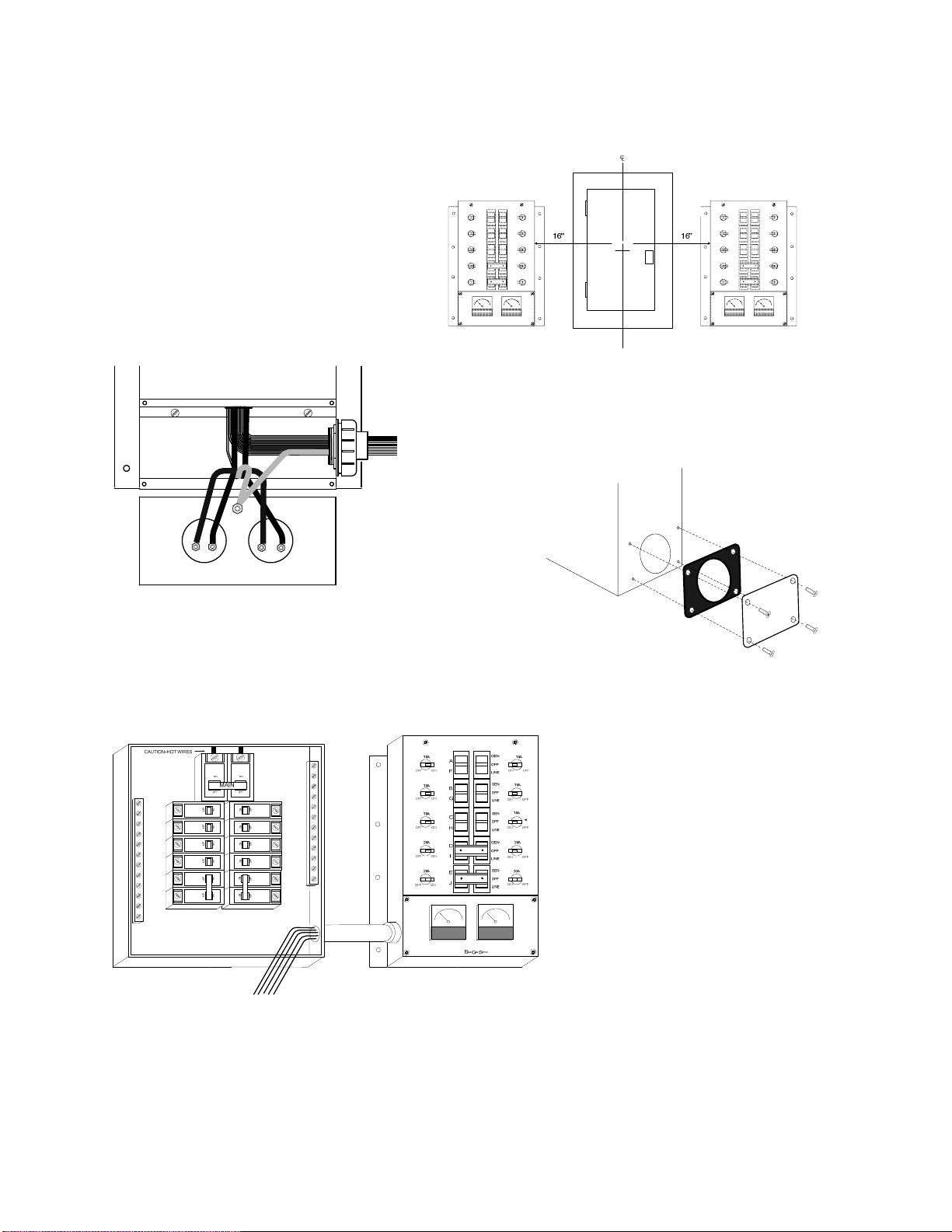
1. Determine where you want your
EmerGen Switch located, either to
the left or right of the load center.
If the EmerGen Switch is to be
located to the right of the load
center, you will need to relocate
the wire bundle out the left side.
The EGS is factory assembled with
the wire bundle exiting right.
4. TURN OFF POWER. The main circuit breaker,
or service disconnect, to your load center
(typically located at the top) should be switched
to the OFF position. CAUTION—THIS DOES NOT
AFFECT THE WIRES ON THE LINE SIDE OF THE MAIN BREAKER—THEY WILL
REMAIN LIVE! Remove the cover of the load center.
Advertissement: Ouvrir L’interrupteur principal ou le disjoncteur dans le panneau de
distribution avant l’installation ou l’entretien.
5. Identify the appropriate
knockout to remove in the load
center. 1” trade size for the 6
circuit models, 1-1/4” for the
10 circuit model.
7. Insert the wires from the conduit through the knockout, taking care not to
nick or gouge the wires on the metal edge. Slide the locknut over the loads and
tighten securely onto the conduit fitting.
8. Without over-manipulating the flex conduit, secure your EmerGen Switch to the
wall with fasteners appropriate for the wall’s construction. If you are mounting
this unit flush in the wall, follow Flush Install Instructions.
6. Trim the supplied conduit
to the desired length and slide
over the EmerGen Switch
wires. Attach to the fitting on
the EmerGen Switch. Slide the
supplied fitting over the wires
and attach to the conduit.
2. To relocate the wire bundle, open the front
cover by removing the four screws. Knock out
the appropriate knockout on the left side. Re-
move conduit fitting and carefully remove
wire bundle and route through the jam nut and
through the hole on the left side. Slide conduit
fitting over leads and secure with jam nut.
3. Cover open hole
with supplied gasket
and cover plate
6

WIRING THE EMERGEN SWITCH TO THE LOAD CENTER
1. From your plan, locate the circuit breaker that is to be connected to the
EmerGen Switch circuit “A”. We will use the refrigerator circuit for this example.
Turn that circuit breaker to the OFF position. Loosen the lug securing the wire
and remove the wire.
WARNING: Transfer switch circuits with 20 amp breakers must be installed to
circuits using 20 amp circuit breakers in your load center. Transfer switch
circuits with 15 amp breakers can be installed on either 15 or 20 amp circuit
breakers in the load center.
DO NOT INSTALL ANY TRANSFER SWITCH CIRCUIT ON BRANCH CIRCUITS
GREATER THAN 20 AMPS.
2. Find both the red and black EmerGen Switch wires labeled “A”. Using good
workmanship, route both of these wires close to the selected circuit breaker.
a) The red EmerGen Switch
“A” wire is trimmed,
stripped and installed into
the circuit breaker,
securely tightening the
breaker lug.
b) The black EmerGen Switch
“A” wire and the hot wire
from the circuit breaker
(removed in step 1) are
placed up the side of the
load center together.
c) After removing 5/8” of the
insulation from the black
EmerGen Switch “A” wire,
insert both wires into an
approved wire connector
and fasten together. Push
the wires back into the
wiring compartment of the
load center.
3. Repeat step 2 for each 120 volt circuit. See the
following section for the installation of 240 volt circuits.
RED (A)
BLACK (A)
WHITE
RED (E)
RED (J)
BLACK (E)
BLACK (J)
GREEN
NEUTRAL BAR
HOME LOAD CENTER
ON
OFF
ON
OFF
MAIN
7

INSTALLING 240 VOLT (2 POLE) CIRCUITS
EmerGen Switch products provide circuits for the connection of 240 volt
appliances that are connected to 2 pole branch circuit breakers in your load
center. These EmerGen Switch circuits for 240 volt operation have a handle tie
installed that ties two circuit selector switches together in the following
positions:
Models 6-7501G2 Circuits C & D
Model 10-7501G2 Circuits D & I, Circuits E & J
If you do not wish to use the designated circuits as 2 pole circuits, simply
remove the handle tie by removing the two screws.
For the purpose of this example, circuits E & J of model 10-7501G2 and a 2-pole
20A well pump circuit in the load center will be used.
a) Start by removing the two load wires from the selected circuit breaker.
b) The red EmerGen Switch “E” wire is trimmed, stripped and securely installed
into one side of the 2 pole circuit breaker.
c) The black EmerGen Switch “E” wire and one of the hot wires from the circuit
breaker are placed up the side of the load center. Insert both wires into a an
approved connector and fasten together. Push the wires back into the wiring
compartment of the load center.
d) The red EmerGen Switch “J” wire is trimmed, stripped and securely installed
into the remaining side of the 2 pole circuit breaker.
e) The black EmerGen Switch “J” wire and the remaining hot wire from the
circuit breaker are placed up the side of the load center. Insert both wires
into an approved wire connector and fasten together. Push the wires back
into the wiring compartment of the load center.
8

COMPLETING THE INSTALLATION
1) When the preceding steps have been completed for all desired circuits, the
EmerGen Switch white (neutral) wire needs to be installed.
a. Select any unused hole on the neutral bar in the load center.
b. Cut and strip the wire appropriately. Insert the wire into the hole
in the neutral bar and tighten securely.
2) The EmerGen Switch green (ground) wire needs to be installed into an unused
hole in the ground bar in the load center.
a. Select an unused hole in the ground bar in the load center.
b. Cut and strip the wire appropriately. Insert the wire into the hole in
the ground bar and tighten securely.
NOTE: If no separate Ground Bar exists, connect the green wire to an unused
position in the Neutral bar.
3) Replace the load center cover. All circuit breakers can now be turned on
including the MAIN circuit breaker.
4) All EGS switches should be in the “Line” position. The “Off” position is
generally not used.
5) Fill out the chart supplied with your EmerGen Switch describing each
emergency circuit and corresponding circuit breaker. Place this label on or
near your EmerGen Switch for easy reference.
EGS Circuit No. Circuit
Circuit at Load Center Description
A8A Freezer
B 5B Rec Room Lights
C 2A Barn Pump
D3A
E4B Lights
F 10B Furnace Fan
EmerGen Switch
9

WIRING THE EMERGEN SWITCH TO THE GENERATOR
RAIN TIGHT
POWER INLET BOX
POWER
GENERATOR
Loadcenter
Electrical
Junction
Box
Wiring the generator to the
EmerGen Switch will require
the use of an outdoor Power
Inlet box, an electrical junction
box and some permanent
wiring.
Mount an electrical junction
box six (6) inches below the
transfer switch. Route the EGS
input wires through 1/2” Type B
conduit and into the junction
box. Use an appropriate 1/2”
fitting to secure the conduit to
the junction box.
Install four conductor (Hot,
Hot, Neutral, Ground)
permanent wiring between the
junction box and power inlet
box according to local code
requirements. Recommended
wire size is 12GA for 20 amp
generators and 10GA for 30
amp generators.
Caution!
Locate inlet box a minimum of 10 feet away
from any opening in the building that would
allow carbon monoxide to enter the premises.
Connect the EmerGen Switch input wires to your
permanent wiring as follows:
1. EGS blue (1) to red (hot)
2. EGS blue (2) to black (hot)
3. EGS white to white (neutral)
4. EGS green to ground
Use an appropriate wire connectors to make the
connections.
Check your local electrical codes for grounding
and bonding requirements for the junction box.
10

OPERATION / TEST PROCEDURE
1. Switch positions should remain in the “LINE” position under normal utility
power. The “OFF” position is generally not used. The “GEN” positions are used
when utilizing your generator power source. Keep the EGS circuit breakers
set in the ON position at all times.
2. When testing and/or switching to generator power after a power outage,
ensure all switches are in the “LINE” position. (There is no need to turn off
any load center circuit breakers including the MAIN circuit breaker).
3. Plug your power cord set into your generator by aligning the male prongs with
the female terminals of your generator’s receptacle, push the connector in
and twist clockwise to lock. Align the female socket of the cord set into your
remote power inlet box, push it in and turn clockwise to lock.
4. Move your generator outdoors before starting it up. Check to see that fluids
and fuel are adequate and start your generator according to the
manufacturer’s instructions. Allow approximately 10 minutes for your
generator to warm up.
5. At your EmerGen Switch, move one circuit to the “GEN” position, making a
note of how much wattage is used on the watt meter. While monitoring the
load, flip each circuit—one at a time—to the “GEN” position. You do not need
to go “in order” and you want to balance the loads so that both meters read
approximately the same. Attempt to balance the two meters to within 1000W
of each other. Do not switch on more loads than your generator can supply.
6. Test generation and transfer switch regularly to ensure proper operation.
Note: Wattage must not exceed the maximum printed on the meters.
LOAD MANAGEMENT
1. All circuits can be used simultaneously if your generator has sufficient
wattage capacity. If an electrical load on the EmerGen Switch is exceeded by its
capacity, the mini-breaker may trip.
To Reset:
a. Eliminate the overload condition.
b. Move the rocker switch with the tripped breaker to the “OFF” position.
c. Reset the breaker by switching it to the OFF position and then to
the ON position.
d. Move the switch back to the “GEN” position. It should now operate
properly. If it does not, you may need to contact an electrician or
qualified professional.
11

Problem Cause Solution
Gen. running but no
output available. 1. Generator circuit breaker
has tripped. 1. Reset circuit breaker.
2. Poor connection or
defective cord set. 2. Check and repair.
3. Connected device is bad. 3. Select a different load or
appliance in good condition.
4. Fault in generator. 4. Contact a qualified
professional.
Generator runs good
but bogs down when
loads are connected.
1. Short circuit in a
connected load. 1. Disconnect shorted electrical
load.
2. Generator is overloaded. 2. Review load power
requirements and rearrange.
Switches not working
with gen. power. 1. Switches are in OFF or LINE
position. 1. Move switches to GEN
position.
2. Generator circuit breaker
has tripped. 2. Reset circuit breaker.
3. Poor connection or
defective cord set. 3. Check and repair.
4. Connected device is bad. 4. Select a different load or
appliance in good condition.
5. Fault in generator. 5. Contact a qualified
professional.
Appliances do not
operate after utility
power is restored.
1. Switches are in GEN or OFF
position. 1. Move switches to LINE
position.
2. Circuit breaker tripped. 2. Reset circuit breaker.
Only some loads
work on generator
p
ower.
1. Circuit breaker tripped. 1. Reset circuit breaker.
2. Switch on generator in
120V position 2. Move generator switch to
120/240V position.
3. Poor connection or
defective cord set. 3. Check and repair.
GFCI breaker on
generator trips when
connected to switch
1. Neutral / Ground bond in
generator 1. The EGS will not function with
a GFCI protected generator
output.
Trouble Shooting
12

Product Warranty
Every EmerGen Switch is guaranteed against mechanical or electrical failure due to
manufacturing defects for a period of five yearsfrom the date ofpurchase.
Connecticut Electric warrants to the purchaser that this product will be free from defects
in material and workmanship and will be of the kind and quality designated. This
warranty shall apply only to defects appearing within one year of the original date of
purchase.
Defective products are to be returned to the place of purchase for an exchange or
refund.
Connecticut Electric will not be liable for any loss, damage, incidental or consequential
damage of any kind, whether based upon warranty contact, or negligence, and/or arising
in connection with the sale, use, installation or repair of this product. Connecticut
Electric’s maximum liability shall not, in any case, exceed the contract price for the
products claimed to be defective or unsuitable.
This warranty does not extend to any product manufactured by Connecticut Electric
which has been subjected to misuse, neglect, accident, improper installation or use in
violation of instructions furnished.
This warranty does not extend to or apply to any unit which has been repaired or altered,
either to the product or to the components manufactured by any other supplier other
than Connecticut Electric.
If you require assistance, contact out Customer Help Line at (800) 730-2557 Ext. 200.
13
This manual suits for next models
1
Table of contents
Other Connecticut Electric Switch manuals