9
User Guide - Powerbrush
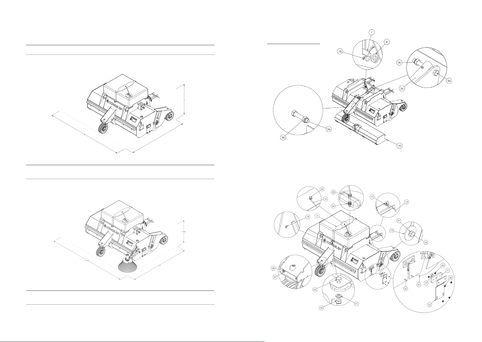
NOTE: These parts are for this model, they may differ for previous versions. Please contact Conquip with any queries.
Item Number Part Number Descripon Quanty
1 ZZ220169 Brush Adjustment Assembly 1
2 ZZ220170 Brush Adjustment Assembly c/w Bearing 1
3ZZ960079 Washer 4mm x OD: 15.5mm x ID:12.5mm 4
4 ZZ220173 Main Brush Sha, Length: 2065mm 1
5 ZZ220174 Water Tank Strap 1
6 ZZ220187 Sha Motor Insert Assembly 1
7ZZ220176 Fork Pocket Retaining Pins 2
8ZZ960078 Washer 6mm x OD:37mm x ID:21mm 2
9 ZZ220177 Sha Bearing Insert Assembly 1
10 ZZ960077 Washer 6mm x OD:73mm x ID:30.5mm 1
11 ZZ220178 Hopper Bearing Bracket 2
12 ZZ220179 Hopper Safety Guard 2
13 ZZ960063 Washer 6mm x OD: 70mm x ID: 17mm 2
14 ZZ990000 Heel Pin, 16mm dia. Max Pocket Width
180mm (Single) 2
15 NS800804 4.8 x 20mm Alu Large Flange Blind (Pop) Rivets 4
16 ZZ990510 Coated Galvanised Restraint Wire, 500mm c/w
Nylon Eye 1
17 ZZ960064 Sleeve Bearing, Oilon, OD: 25mm x ID:15mm
x 28mm 2
18 ZZ220167 Splined Hub, 8mm Key, 100mm L, OD: 50mm
Ø, ID: 25mm Ø 1
19 ZZ990009 Linch Pin 6mm x 42mm 4
20 NS800013 M10 Nyloc Nut 18
21 NS800262 M10 Steel Washer A BZP 2
22 NS800888 M10 x 30mm Coach Bolt 4
23 NS800666 M10 X 30 Hex Head set BZP 2
24 NS800066 M10 x 35 8.8 HT Hex Head Set Screw BZP 1
25 NS800622 M8 x 30 Hex Head Set Screw BZP 1
26 NS800860 M10x60 Coach Bolt 4
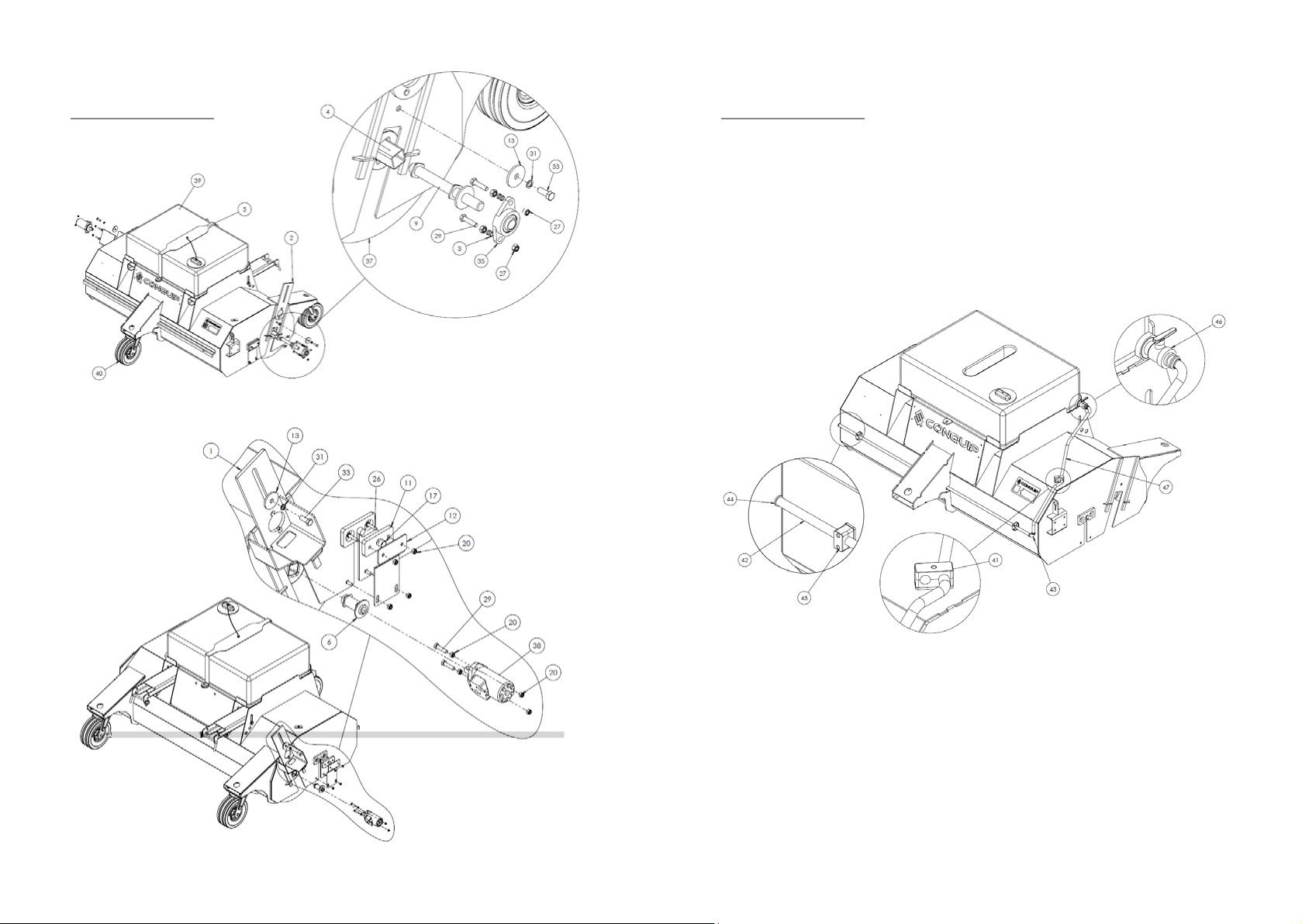
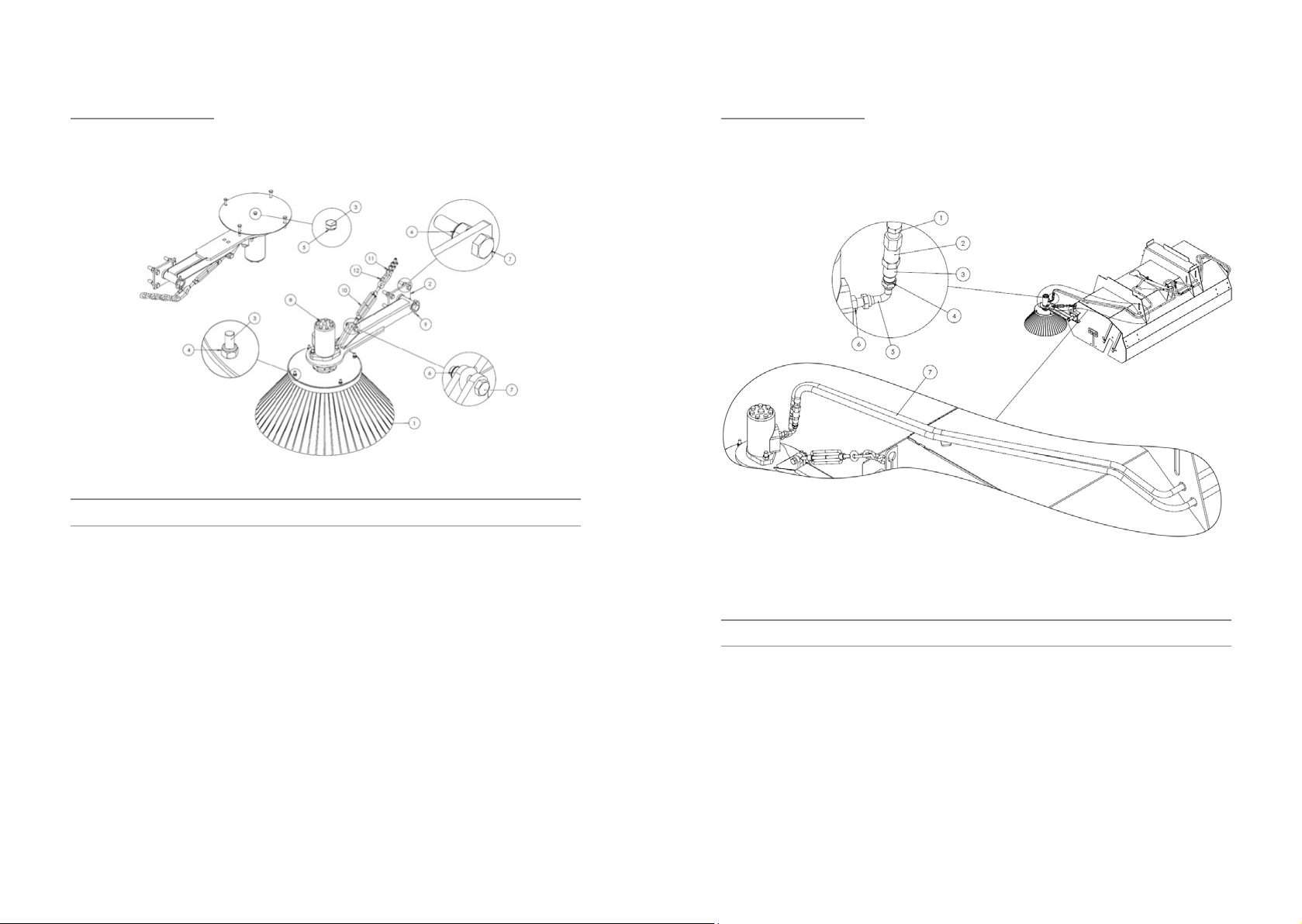
NOTE: These parts are for this model, they may differ for previous versions. Please contact Conquip with any queries.
Item Number Part Number Descripon Quanty
27 NS800015 M12 Nyloc Nut BZP 16
28 NS800889 M12 x 40 Hex Head Set Screws 8.8 HT 12
29 NS800817 M12 x 50 8.8 HT BZP Hex Set Screws 4
30 NS800121 M16 Nyloc Nuts BZP 2
31 NS800249 M16 Spring Washer 2
32 NS800566 M16 x 130 Bolts BZP 1
33 NS800379 M16 x 40 Set Screw 2
34 NS800801 M16 x 70 Bolt BZP 1
35 ZZ220003 Flanged Bearing, 30mm c/w Grease Nipple 1
36 ZZ960065 Hydraulic Cylinder, 20mm Ø Piston, 400mm
Stroke 1
37 ZZ270000 Brush 100% PPN 295mm x 600mm Ø 7
38 ZZ220185 Hydraulic Motor AGMR 160 1
39 ZZ990506 Water Tank, 250L, c/w Conquip Branding 1
40 ZZ270141 Swivel Castor, Heavy Duty, 305mm Wheel
Diameter 3
41 ZZ220180 Hydraulic Double Hose Clamp, 3/8” 2
42 ZZ220042 2m UPVC Pipe, ID: ½” 1
43 ZZ220040 90° Elbow, ½” Thread, ½” Solvent UPVC 1
44 ZZ220043 End Cap, ID: ½” Solvent UPVC 1
45 ZZ220181 Hydraulic Single Hose Clamp, ½” 2
46 ZZ220126 Water Tap 1
47 ZZ220125 PVC Water Hose 1