Conrad 12V/160W User manual

Impressum
Diese Bedienungsanleitung ist eine Publikation der Conrad Electronic GmbH.
Alle Rechte einschließlich Übersetzung vorbehalten. Reproduktionen jeder Art, z. B.
Fotokopie, Mikroverfilmung, oder die Erfassung in elektronischen Datenverarbei-
tungsanlagen, bedürfen der schriftlichen Genehmigung des Herausgebers.
Nachdruck, auch auszugsweise, verboten.
Diese Bedienungsanleitung entspricht dem technischen Stand bei Drucklegung.
Änderung in Technik und Ausstattung vorbehalten.
©
Copyright 2002 by Conrad Electronic GmbH. Printed in Germany.
Imprint
These operating instructions are published by Conrad Electronic GmbH, Klaus-
Conrad-Str. 1, 92240 Hirschau/Germany
No reproduction (including translation) is permitted in whole or part e.g. photoco-
py, microfilming or storage in electronic data processing equipment, without the
express written consent of the publisher.
The operating instructions reflect the current technical specifications at time of
print. We reserve the right to change the technical or physical specifications.
©
Copyright 2002 by Conrad Electronic GmbH. Printed in Germany.
Note de l´éditeur
Cette notice est une publication de la société Conrad Electronic GmbH, Klaus-
Conrad-Str. 1, 92240 Hirschau/Allemagne.
Tous droits réservés, y compris traduction. Toute reproduction, quel que soit le
type, par exemple photocopies, microfilms ou saisie dans des traitements de texte
electronique est soumise à une autorisation préalable écrite de l`éditeur.
Impression, même partielle, interdite.
Cette notice est conforme à la règlementation en vigueur lors de l´impression.
Données techniques et conditionnement soumis à modifications sans aucun préalable.
©
Copyright 2002 par Conrad Electronic GmbH. Imprimé en Allemagne.
*05-02/WM
CONRAD IM INTERNET http://www.conrad.de
100 %
recycling
paper.
Bleached with-
out
chlorine.
100 %
Recycling-
Papier.
Chlorfrei
gebleicht.
100%
papier
recyclé.
Blanchi
sans
chlore.
Version 05/02
Spannungswandler Seite 4 - 13
Voltage converter Page 14 - 23
Transformateur
de tension Page 24 - 33
Best.-Nr. / Item-No. / Node commande:
51 21 00 12V / 230V 160W
51 21 02 12V / 230V 220W
51 21 04 12V / 230V 500W
51 21 06 12V / 230V 1000W
51 21 03 12V / 230V 1700W
51 21 05 24V / 230V 160W
51 21 01 24V / 230V 220W
51 21 07 24V / 230V 500W
51 21 08 24V / 230V 1000W
51 21 09 24V / 230V 1700W
BEDIENUNGSANLEITUNG OPERATING INSTRUCTIONS
MODE D’EMPLOI
2
Diese Bedienungsanleitung gehört zu diesem Produkt. Sie enthält
wichtige Hinweise zur Inbetriebnahme und Handhabung. Achten Sie
hierauf, auch wenn Sie dieses Produkt an Dritte weitergeben.
Heben Sie deshalb diese Bedienungsanleitung zum Nachlesen auf!
Eine Auflistung der Inhalte finden Sie in dem Inhaltsverzeichnis mit Angabe
der entsprechenden Seitenzahlen auf Seite 5.
The present operating manual forms part of this product. It con-
tains important information on how to assemble the product and put it
into operation. Please take due note of it if you should give the product
to third parties.
So keep this operating manual for your future reference!
You will find a list of the contents in the Table of Contents page 15 indicating
the corresponding pages.
Le mode d’emploi suivant correspond au produit ci-dessus men-
tionné. Il comporte des instructions importantes relatives à sa mise en
service et à son maniement ! Il faut respecter ces instructions, même si
ce produit est transmis à tierce personne !
Gardez ce mode d’emploi pour toute consultation ultérieure !
Vous trouverez une liste des matières dans l’index page 25 avec indication
des pages correspondantes à consulter.

3
4
Einführung
Sehr geehrter Kunde,
der Aufbau entspricht der Niederspannungsrichtlinie 73/23/EWG. Darüber hinaus ist
es EMV-geprüft und entspricht somit den Anforderungen der geltenden europäi-
schen und nationalen Richtlinien (CE).
Die Konformität wurde nachgewiesen; die entsprechenden Erklärungen und Unterla-
gen sind beim Hersteller hinterlegt.
Um diesen Zustand zu erhalten und einen gefahrlosen Betrieb sicherzustellen müs-
sen Sie als Anwender diese Bedienungsanleitung beachten!
Bei Fragen wenden Sie sich an unsere Technische Beratung
Deutschland: Tel. 0180/5 31 21 16 oder 09604/40 88 47
Fax 09604/40 88 44
e-mail: [email protected]
Mo. - Fr. 8.00 bis 18.00 Uhr
Österreich: Tel. 0 72 42/20 30 60 · Fax 0 72 42/20 30 66
e-mail: [email protected]
Mo. - Do. 8.00 bis 17.00 Uhr
Fr. 8.00 bis 14.00 Uhr
Schweiz: Tel. 0848/80 12 88 · Fax 0848/80 12 89
e-mail: [email protected]
Mo. - Fr. 8.00 bis 12.00 Uhr, 13.00 bis 17.00 Uhr
Bestimmungsgemäßer Einsatz
Die Spannungswandler sind nur zum Betrieb an 12V bzw. 24V Gleichspannung (je
nach Geräteausführung) zugelassen.
Die Spannungswandler dürfen nur in trockenen und geschlossenen Räumen in
Betrieb genommen werden. Ein Betrieb der Spannungswandler in Fahrzeugen der
StVZO ist während der Fahrt nicht zulässig.
Der Anschluss erfolgt für die 160W und 220W- Wandler über einen Zigarettenanzün-
derstecker. Die 500W, 1000W und 1700W-Spannungswandler müssen fest an der
Spannungsquelle mit den beiliegenden Leitungen angeschlossen werden. Die Lei-
tungen dürfen nicht verlängert werden.
Zum Betrieb am Spannungswandler sind Geräte geeignet wie z.B. Fernsehgeräte,
Kleinmaschinen, Lampen usw., die eine Netzspannung von 230 V benötigen.
33
Caractéristiques techniques
Spécifications 12 V/160 W 12 V/220 W 12 V/500 W 12 V/1000 W 12V/1700 W
12 V/160 W 24 V/220 W 24 V/500 W 24 V/1000 W 24V/1700 W
Tension 12 V DC (de 11,5 à 14 V DC)
d’entrée 24 V DC (de 22 V à 28 V DC)
Courant à vide 380 mA 460 mA 750 mA 1,6 A 2,3 A
absorbé, 200 mA 300 mA 420 mA 1,0 A 1,6 A
environ
Tension de sortie 230 V AC rms 50 Hz (rms = effectif)
Mode de tension Sinus modifié (rectangulaire)
Rendement 80%
Puissance
nominale 160 W 220 W 500 W 1000 W 1700 W
de sortie
Puissance de
pointe au 220 W 450 W 1000 W 1800 W 3000 W
démarrage
Protection 20 A 30 A 2x 30 A 4x 30 A 6x 30 A
d’entrée DC; jaune vert vert vert vert
FKS
Poids, env. 550 g 685 g 1500 g 2400 g 3500 g
Dimensions 185 x 80 x 210 x 80 x 235 x 130 x 335 x 150 x 335 x 195 x
(Long. x larg. 50 (mm) 50 (mm) 70 (mm) 66 (mm) 76 (mm)
x haut.)
Branchement prise allume- prise allume- bornes bornes bornes
cigare cigare à visser à visser à visser
8 mm 8 mm 10 mm
Longueur des
câbles de 75 cm 75 cm 100 cm 100 cm 100 cm
branchement
Section des
câbles 2,5 mm22,5 mm210 mm216 mm22x16 mm2
Refroidisse-
ment Boîtier Ventilateur Ventilateur Ventilateur 2xVentilateur
Signalement de
surtension > 14,3 V / > 28,6 V
Protection contre Alarme acoustique: <11,3V (version 12V) < 22,6V (version 24V)
sous-tension Mise hors circuit <10,7V (version 12V) < 21,4V (version 24V)

32
Problème Cause éventuelle
- Le transformateur est-il allumé ?
Pas de fonctionnement, le - Les fusibles sont-ils défectueux ?
voyant de fonctionnement n’est Contrôlez les fusibles plats.
pas allumé. - L’alimentation en tension est-elle bonne ?
Contrôlez la tension d’alimentation (piles
déchargées etc.).
En allumant ou pendant le - L’alimentation en tension est trop basse (la pro
service, un signal sonore se tection contre une décharge totale est activée)
fonctionnement (3) est rouge. Rechargez la batterie!
- Nettoyez les contacts de la fiche pour l’allume-
cigares (perte de puissance)
En allumant, le voyant de - Contrôlez l’alimentation en tension (surtension
fonctionnement (3) est rouge. ou sous-tension !)
Après avoir allumé un - La puissance de démarrage ou nominale du
consommateur, le consommateur est trop élevée. Contrôlez les
transformateur de caractéristiques techniques.
tension s’éteint. Le voyant de - Pour réactiver la sortie, éteignez et rallumez le
surcharge (2) est rouge. transformateur.
Vérifiez régulièrement le bon état de l’appareil quant à la sécurité tech-
nique par exemple endommagements du boîtier, etc.
Toute autre réparation doit être effectuée uniquement par un spécialiste ayant con-
naissance des dangers liés à la réparation et des directives correspondantes. Toute
transformation ou réparation effectuées par une personne non-qualifiée ont pour
conséquence l’annulation de la garantie.
5
Die Dauerleistungsaufnahme bzw. die Anlaufleistung der angeschlossenen Verbrau-
cher darf die Nennleistung bzw. die Spitzenleistung des Wandlers nicht überschrei-
ten.
Die Verwendung von Mehrfach-Steckdosenverteilern ist nicht zulässig; Verwenden
Sie nur die vorhandenen Steckdosen (Euro und/ oder Schuko).
Die Gesamtzahl der Leistung der angeschlossenen Verbraucher darf die Nennlei-
stung des Wandlers nicht überschreiten.
An die Euro-Steckdosen der Spannungswandler dürfen nur Geräte der Schutzklasse
2 (Schutzisoliert) angeschlossen werden.
Ein Anschluss an das öffentliche Stromnetz zur Einspeisung ist verboten (!) und tech-
nisch nicht möglich (keine Netzsynchronisation).
Ein Betrieb unter widrigen Umgebungsbedingungen ist nicht zulässig. Widrige
Umgebungsbedingungen sind:
- Nässe oder zu hohe Luftfeuchtigkeit,
- Staub und brennbare Gase, Dämpfe oder Lösungsmittel,
- Hohe Umgebungstemperaturen.
Eine andere Verwendung als zuvor beschrieben, führt zur Beschädigung dieses Pro-
duktes, außerdem ist dies mit Gefahren wie z.B. Kurzschluss, Brand, elektrischer
Schlag etc. verbunden. Das gesamte Produkt darf nicht geändert bzw. umgebaut
werden! Die Sicherheitshinweise sind unbedingt zu beachten!
Inhaltsverzeichnis
Einführung . . . . . . . . . . . . . . . . . . . . . . . . . . . . . . . . . . . . . . . . . . . . . . . . . . . . . . . . . 4
Bestimmungsgemäßer Einsatz . . . . . . . . . . . . . . . . . . . . . . . . . . . . . . . . . . . . . . . . . 4
Inhaltsverzeichnis . . . . . . . . . . . . . . . . . . . . . . . . . . . . . . . . . . . . . . . . . . . . . . . . . . . 5
Bedienelemente . . . . . . . . . . . . . . . . . . . . . . . . . . . . . . . . . . . . . . . . . . . . . . . . . . . . 6
Sicherheits- und Gefahrenhinweise . . . . . . . . . . . . . . . . . . . . . . . . . . . . . . . . . . . . . 6
Funktionsbeschreibung . . . . . . . . . . . . . . . . . . . . . . . . . . . . . . . . . . . . . . . . . . . . . . . 8
Inbetriebnahme . . . . . . . . . . . . . . . . . . . . . . . . . . . . . . . . . . . . . . . . . . . . . . . . . . . . . 9
Allgemein . . . . . . . . . . . . . . . . . . . . . . . . . . . . . . . . . . . . . . . . . . . . . . . . . . . . . . . . 9
DC-Anschluss der Spannungswandler . . . . . . . . . . . . . . . . . . . . . . . . . . . . . . . . . 9
Anschluss eines Wechselspannungs-Verbrauchers . . . . . . . . . . . . . . . . . . . . . . 10
Wartung und Reinigung . . . . . . . . . . . . . . . . . . . . . . . . . . . . . . . . . . . . . . . . . . . . . 10
Sicherungswechsel . . . . . . . . . . . . . . . . . . . . . . . . . . . . . . . . . . . . . . . . . . . . . . . 11
Kontaktkontrolle . . . . . . . . . . . . . . . . . . . . . . . . . . . . . . . . . . . . . . . . . . . . . . . . . 11
Behebung von Störungen . . . . . . . . . . . . . . . . . . . . . . . . . . . . . . . . . . . . . . . . . . . . 11
Technische Daten . . . . . . . . . . . . . . . . . . . . . . . . . . . . . . . . . . . . . . . . . . . . . . . . . . 13

6
Bedienelemente
(Abbildung siehe Ausklappseite)
(1) Netzschalter zur Inbetriebnahme (I = EIN / 0 = AUS)
(2) Überlastanzeige rotleuchtend (Overload =Überlast)
(3) Zweifarbige Betriebsanzeige
grün= Wechselspannung OK
rot = Über-/ Unterspannung
(4) Euro-Steckdose für Schutzklasse 2- Verbraucher
Modell 160 W / 220 W = eine Steckdose
Modell 500 W = drei Steckdosen
Modell 1000 W = eine Steckdose
Modell 1700 W = zwei Steckdosen
(5) Lüftungsöffnungen für eingebauten Lüfter (nicht bei 160W-Wandler)
(6) DC-Anschlussleitung
(7) Zigarettenanzünder- Stecker (nur Modell 160 W und 220 W)
(8) DC-Eingangssicherung (Sicherungen variieren je nach Modell)
(9) Schuko-Steckdose für Verbraucher der Schutzklasse 1 und 2 (nur bei Modell
1000 W und 1700 W)
(10) Schraubklemme "Minuspol" (-)
(11) Schraubklemme "Pluspol" (+)
Sicherheits- und Gefahrenhinweise
Bei Schäden, die durch Nichtbeachten dieser Bedienungsanlei-
tung verursacht werden, erlischt der Garantieanspruch! Für Fol-
geschäden und bei Sach- oder Personenschäden, die durch
unsachgemäße Handhabung oder Nichtbeachten der Sicherheits-
hinweise verursacht werden, übernehmen wir keine Haftung!
• Dieses Gerät hat das Werk in sicherheitstechnisch einwandfreien Zustand verlas-
sen.
Um diesen Zustand zu erhalten und einen gefahrlosen Betrieb sicherzustellen,
muss der Anwender die Sicherheitshinweise und Warnvermerke beachten ("Ach-
tung!" und "Hinweis!"), die in dieser Gebrauchsanweisung enthalten sind. Folgen-
de Symbole gilt es zu beachten:
31
Changement de fusibles
Les transformateurs de tension sont protégés contre un court-circuit ou une sur-
charge du côté de l’alimentation DC par des fusibles plats usuels (fusibles automobi-
le plat FKS).
Si le transformateur de tension ne se laisse plus allumer (l’interrupteur d’alimentation
et le voyant de fonctionnement ne sont plus allumés), le (ou les) fusible(s) d’entrée
DC est (sont) probablement défectueux.
Pour changer les fusibles procédez de la façon suivante:
• Éteignez le transformateur de tension et débranchez tous les consommateurs de
l’appareil.
• Retirez alors tous les fusibles (8) des porte-fusibles et remplacez-les par des
fusibles ayant la même intensité (voir caractéristiques techniques)
• Assurez-vous après le changement que les fusibles plats sont bien enfoncés.
Attention! Assurez-vous que vous n’utilisez que des fusibles de
rechange du type et de l’intensité nominale indiqués. Il est interdit
d’utiliser des fusibles rafistolés ou de court-circuiter le porte-fusible.
Contrôle des contacts
Contrôlez régulièrement si les contacts sont vissés solidement afin d’éviter les résis-
tance de contact (perte de puissance).
L’intervalle de contrôle dépend des conditions environnementales
- Pas de sollicitations mécaniques de l’appareil ni des câbles ➔environ une fois
par an,
- Légères sollicitations mécaniques de l’appareil et des câbles ➔environ tous les
3 à 4 mois.
Suppression d’anomalies
Avec le transformateur de tension, vous avez acquis un produit fiable et sûr. D’éven-
tuels problèmes ou anomalies pouvant cependant subvenir, nous décrivons ci-des-
sous comment parer vous-même à ces dérangements :
Prenez absolument compte des avertissements concernant la
sécurité !

30
• Veillez ici aussi à visser solidement les bornes sur les pôles ; si nécessaire, utilisez
de la graisse pour pôles de batterie.
• Vérifiez encore une fois si les câbles sont raccordés correctement selon la polarité
prévue !
• Allumez le transformateur à l’aide de l’interrupteur d’alimentation (1). Le voyant de
fonctionnement (3) doit être vert et l’interrupteur d’alimentation rouge.
• La sortie de la tension alternative est alors activée.
• Pour éteindre le transformateur, appuyez sur l’interrupteur d’alimentation (position
0). L’éclairage de l’interrupteur et du voyant de fonctionnement (3) s’éteint.
Branchement d’un consommateur à courant alternatif
• Assurez-vous que le consommateur soit éteint et que la puissance nominale ou la
puissance de démarrage correspondent au type de transformateur utilisé.
• Raccordez la fiche avec une prise appropriée (4 ou 9)
• Allumez le transformateur à l’aide de l’interrupteur d’alimentation (1), l’interrupteur
est illuminé et le voyant de fonctionnement (3) doit être vert. Si le voyant est rouge
veuillez lire le chapitre « Suppression d’anomalies ».
• Allumez ensuite le consommateur branché.
Veillez à ne jamais dépasser le maximum de la puissance nominale
continue ou de la puissance de pointe de démarrage des transforma-
teurs de tension correspondants. Respectez la puissance de démarra-
ge et la résistance à froid. Celle-ci est 10 fois plus haute pour des
ampoules électriques que lors du service nominal. Un réfrigérateur à
compression par exemple ne peut être mis en service qu’avec le
modèle 1700 W (150 W x 10 = 1500 W)
Entretien et nettoyage
Les transformateurs ne nécessitent pratiquement aucun entretien si ce n’est un net-
toyage occasionnel et un contrôle des contacts (seulement modèles 500W, 1000W
et 1700W) et un changement des fusibles quand c’est nécessaire. Pour le nettoyage
de l’appareil, prenez un chiffon propre, non pelucheux, antistatique et légèrement
humide. N’utilisez pas de détergents chimiques, ni contenant des abrasifs ni des dis-
solvants pour le nettoyage.
Attention ! Assurez-vous toujours d’avoir éteint le transformateur
avant de nettoyer l’appareil.
7
= Hinweis! Lesen Sie die Gebrauchsanweisung!
= Anschlusspunkt für den inneren Schutzleiter; diese Schraube darf
nicht gelöst werden (Schutzklasse I)
= Schutzklasse 2 (Schutzisoliert)
= Nur zur Verwendung in trockenen Innenbereichen.
°= Dieses Gerät ist CE-geprüft und erfüllt somit die erforderliche
EMV-Richtlinie 89/336/EWG und Niederspannungsrichtlinie
73/23/EWG.
• Elektrogeräte und Zubehör gehören nicht in Kinderhände!
• Es dürfen keine Geräte zur Lebensrettung /-erhaltung an den Spannungswandler
angeschlossen werden.
• Benutzen Sie diese Spannungswandler nicht in leicht entflammbaren Umgebun-
gen in denen sich brennbare Gase oder Stäube befinden oder auf leicht entflamm-
baren Oberflächen.
• In gewerblichen Einrichtungen sind die Unfallverhütungsvorschriften des Verban-
des der gewerblichen Berufsgenossenschaften für elektrische Anlagen und
Betriebsmittel zu beachten.
• In Schulen und Ausbildungseinrichtungen, Hobby- und Selbsthilfewerkstätten ist
der Umgang mit Elektronischen Geräten durch geschultes Personal verantwortlich
zu überwachen.
• Achten Sie darauf, dass ihre Hände, Schuhe, Kleidung, der Boden und der Span-
nungswandler unbedingt trocken sind.
• Beim Öffnen von Abdeckungen oder Entfernen von Teilen können Spannungs-
führende Teile freigelegt werden.
• Vor einem Öffnen, muss das Gerät von allen Spannungsquellen getrennt werden.
• Kondensatoren im Gerät können noch geladen sein, selbst wenn das Gerät von
allen Spannungsquellen getrennt wurde.
• Schalten Sie den Spannungswandler niemals gleich dann ein, wenn er von einem
kalten in einen warmen Raum gebracht wird. Das dabei entstandene Kondens-
wasser kann unter ungünstigen Umständen Ihr Gerät zerstören. Lassen Sie das
Gerät uneingeschaltet auf Zimmertemperatur kommen.

8
• Der Spannungswandler erwärmt sich bei Betrieb; Achten Sie auf eine ausreichen-
de Belüftung. Lüftungsschlitze dürfen nicht abgedeckt werden!
• Spannungswandler und die angeschlossenen Verbraucher dürfen nicht unbeauf-
sichtigt betrieben werden.
• Es dürfen nur Sicherungen vom angegebenen Typ und der angegebenen Nenn-
stromstärke verwendet werden. Die Verwendung geflickter Sicherungen ist unter-
sagt.
• Die Verwendung metallisch blanker Leitungen ist zu vermeiden.
• Wenn anzunehmen ist, dass ein gefahrloser Betrieb nicht mehr möglich ist, so ist
das Gerät außer Betrieb zu setzen und gegen unbeabsichtigten Betrieb zu sichern.
Es ist anzunehmen, dass ein gefahrloser Betrieb nicht mehr möglich ist, wenn:
- das Gerät sichtbare Beschädigungen aufweist,
- das Gerät nicht mehr arbeitet und
- nach längerer Lagerung unter ungünstigen Verhältnissen oder
- nach schweren Transportbeanspruchungen.
• Beachten Sie auch die Sicherheitshinweise in den einzelnen Kapiteln bzw. in den
Bedienungsanleitungen der angeschlossenen Geräte.
Funktionsbeschreibung
Die Spannungswandler erzeugen aus einer Gleichspannung (12 V DC oder 24 V DC)
eine Sinusähnliche Wechselspannung von 230V mit einer Frequenz von 50 Hz, wel-
che den Betrieb der meisten Geräte ermöglicht.
Durch die Schaltnetzteiltechnologie wird eine enorme Gewichts- und Größenein-
sparung, bei einem guten Wirkungsgrad erreicht.
Die 160 W und 220 W-Wandler sind portabel und mit Stecker für den Zigarettenan-
zünder versehen. Die 500 W, 1000 W und 1700 W-Wandler sind für Festmontage
ausgelegt. Der Anschluss erfolgt über vergoldete Schraubklemmen.
Zur Kühlung ist ein Gerätelüfter eingebaut (ausgenommen 160 W Version, hier erfolgt
die Kühlung durch das Gehäuse).
Alle Spannungswandler sind im DC-Eingangsbereich abgesichert.
Eine DC-Überspannungs- und Unterspannungsschutzabschaltung schützt den
Wandler und verhindert eine Tiefentladung der DC-Spannungsquelle; desweiteren
besitzen diese Wandler einen Überlast- und Kurzschlussschutz, der den 230-V Aus-
gang im Fehlerfall abschaltet und dies optisch signalisiert.
Zur Betriebskontrolle ist der Betriebsschalter beleuchtet und der Zustand der Wech-
selspannungsausgänge wird über eine Zweifarbige Leuchtdiode (Duo-LED) ange-
zeigt.
29
Mise en service
Généralités
Assurez-vous que la prise allume-cigares est bien homologuée pour absorber la
puissance nominale du transformateur lorsque vous voulez l’y branchez (voir carac-
téristiques techniques).
Veillez à ce que l’alimentation de tension soit suffisante (capacité de la batterie) pour
assurer une durée de fonctionnement suffisante.
Prenez soin à ce que le transformateur soit suffisamment aéré et ne couvrez jamais
les fentes d’aération.
Choisissez un emplacement permettant de faire fonctionner le transformateur dans
une température ambiante d’environ 0 à 40°C.
Branchement DC des transformateurs de
tension
Type de transformateur: 160 W et 220 W
• Assurez-vous qu’aucun consommateur ne soit branché au transformateur et que
l’interrupteur d’alimentation (1) se trouve en position « 0 ».
• Branchez la fiche (7) dans une prise allume-cigares appropriée.
• Allumez le transformateur à l’aide de l’interrupteur d’alimentation (1). Le voyant de
fonctionnement (3) doit être sur vert et l’interrupteur d’alimentation sur rouge.
• La sortie de la tension alternative est alors activée.
• Pour éteindre le transformateur, appuyez sur l’interrupteur d’alimentation (position
0). L’éclairage de l’interrupteur et du voyant de fonctionnement (3) s’éteint.
Type de transformateur: 500 W, 1000 W et 1700 W
• Assurez-vous qu’aucun consommateur ne soit branché au transformateur et que
l’interrupteur d’alimentation (1) se trouve en position « 0 ».
• Enlevez les deux écrous dorés des bornes à visser (10 et 11),
• Raccordez les câbles de branchement joints avec les bornes à visser:
- câble rouge avec borne rouge « + » (11)
- câble noir avec borne noire « - » (10)
• Assurez-vous de bien revisser les écrous afin d’éviter une résistance de contact et
empêcher le développement de chaleur sur les bornes.
• Raccordez alors le câble noir directement avec le pôle négatif (-) et ensuite le câble
rouge avec le pôle positif (+) de la batterie d’alimentation.

28
des conditions défavorables, détruire l’appareil. Laissez donc l’appareil débranché
prendre la température ambiante avant de le mettre en marche.
• Le transformateur de tension s’échauffe pendant l’utilisation. Faites attention à ce
qu’il y ait une aération suffisante. Ne couvrez pas les fentes d’aération !
• Ne laissez jamais le transformateur de tension et les consommateurs raccordés
fonctionner sans surveillance.
• Assurez-vous que vous n’utilisez que des fusibles de rechange du type et de l’in-
tensité nominale indiqués. Il est interdit d’utiliser des fusibles rafistolés.
• Évitez l’utilisation de câbles métalliques dénudés.
• S’il est probable qu'une utilisation sans danger n'est plus possible, l'appareil doit
être mis hors service et protégé contre toute utilisation involontaire. Une utilisation
sans danger n'est plus possible si
- l'appareil présente des dommages visibles,
- l'appareil ne fonctionne plus et
- après un long stockage dans des conditions défavorables ou
- après des conditions de transport défavorables.
• Respectez aussi les consignes de sécurité dans chaque chapitre ou dans les
modes d’emploi des appareils branchés.
Description du fonctionnement
Les transformateurs de tension servent à transformer une tension continue (12 V DC
ou 24 V DC) en une tension alternative sinusoïde de 230V avec une fréquence de 50
Hz, qui permet l’utilisation de la plupart des appareils.
Grâce à la technologie de l’alimentation en courant discontinue, un gain énorme en
poids et en taille est obtenu tout en garantissant un bon rendement.
Les transformateurs de 160 W et de 220 W sont portables et équipés d’une fiche
pour l’allume-cigares. Les transformateurs de 500 W, 1000 W et de 1700 W sont pré-
vus pour un montage fixe. Le branchement s’effectue à l’aide de bornes à visser
dorées.
L’aération est assurée par un ventilateur intégré (sauf version de 160 W où l’aération
s’effectue par le boîtier).
Tous les transformateurs de tension sont protégés dans la zone d’entrée DC.
Un déclenchement de surtension ou à minimum de tension DC protège le transfor-
mateur et empêche une décharge totale de la source de tension. De plus, les trans-
formateurs possèdent une protection de surcharge et de court-circuit qui interrompt
la sortie de 230-V en cas de défaut et le signalise par un signal optique.
Afin de pouvoir contrôler le fonctionnement, l’interrupteur d’alimentation est éclairé
et l’état des sorties de la tension alternative est signalisé par une diode électrolumi-
nescente bicolore (LED duo).
9
Inbetriebnahme
Allgemein
Vergewissern Sie sich beim Anschluss der Wandler mit Zigarettenanzünderstecker,
ob die Zigarettenanzündersteckdose für die Nennleistungsaufnahme des Wandlers
ausgelegt ist (siehe Techn. Daten).
Achten Sie auf eine ausreichende Spannungsversorgung (Batteriekapazität) um eine
zufriedenstellende Betriebszeit zu gewährleisten.
Achten Sie unbedingt auf eine ausreichende Be- und Entlüftung bzw. dass die Lüf-
tungsöffnungen nicht abgedeckt werden.
Wählen Sie einen Standort für den Spannungswandler mit einer Umgebungstempe-
ratur von ca. 0 bis 40°C
DC-Anschluss der Spannungswandler
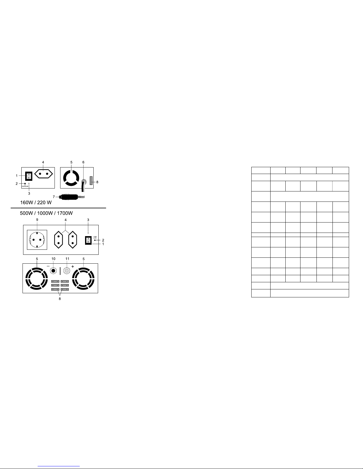
Wandlertyp: 160 W und 220 W
• Vergewissern Sie sich, dass kein Verbraucher am Spannungswandler angeschlos-
sen und der Betriebsschalter (1) in Position "0" ist.
• Stecken Sie den Stecker (7) in eine geeignete Zigarettenanzünder-Steckdose.
• Schalten Sie den Spannungswandler über den Betriebsschalter (1) ein; Die
Betriebsanzeige (3) muss grün, sowie der Betriebsschalter rot leuchten.
• Der Wechselspannungsausgang ist nun aktiv.
• Um den Spannungswandler auszuschalten, betätigen Sie den Betriebsschalter
(Position 0). Die Schalterbeleuchtung und die Betriebsanzeige (3) erlöschen.
Wandlertyp: 500 W, 1000 W und 1700 W
• Vergewissern Sie sich, dass kein Verbraucher am Spannungswandler angeschlos-
sen und der Betriebsschalter (1) in Position "0" ist.
• Entfernen Sie die beiden vergoldeten Schraubmuttern der Anschlussklemmen (10
und 11),
• Verbinden Sie die beiliegenden Anschlussleitungen mit den Anschlussklemmen:
- rote Leitung mit rot markierter Klemme "+" (11)
- schwarze Leitung mit schwarz markierter Klemme "-" (10).
• Verschrauben Sie die Schraubmuttern wieder sorgfältig, um Übergangswiderstän-
de und somit Wärmebildung an den Klemmstellen zu vermeiden.
• Verbinden Sie nun die schwarze Leitung direkt mit dem Minuspol (-) und danach
die rote Leitung direkt mit dem Pluspol (+) der Versorgungsbatterie.
• Achten Sie auch hier auf sichere und feste Verschraubung der Polklemmen;
Benutzen Sie ggf. Batteriepolfett.

10
• Kontrollieren Sie nochmals die Verdrahtung auf korrekte Polarität!
• Schalten Sie den Spannungswandler über den Betriebsschalter (1) ein; Die
Betriebsanzeige (3) muss grün, sowie der Betriebsschalter rot leuchten.
• Der Wechselspannungsausgang ist nun aktiv.
• Um den Spannungswandler auszuschalten, betätigen Sie den Betriebsschalter
(Position 0). Die Schalterbeleuchtung und die Betriebsanzeige (3) erlöschen.
Anschluss eines Wechselspannungs-Verbrauchers
• Vergewissern Sie sich, dass der Verbraucher ausgeschaltet und die Nenn- bzw.
Anlaufleistung für den verwendeten Wandlertyp zulässig ist.
• Verbinden Sie den Netzstecker mit einer passenden Steckdose (4 oder 9)
• Schalten Sie den Wandler über den Betriebsschalter (1) ein; der Schalter ist
beleuchtet und die Betriebsanzeige (3) muss grün leuchten. Leuchtet diese Anzei-
ge rot, so lesen Sie bitte in Kapitel "Behebung von Störungen" nach.
• Schalten Sie nun den angeschlossenen Verbraucher ein.
Überschreiten Sie niemals die maximal zulässige Dauernennleistung
bzw. Spitzenanlaufleistung der entsprechenden Spannungswandler.
Beachten Sie die Anlaufleistung bzw. den Kaltwiderstand. Dieser ist
bei Glühlampen 10 x höher als bei Nennbetrieb; Ein Kompressorkühl-
schrank kann deshalb nur mit Modell 1700 W betrieben werden (150 W
x 10 = 1500 W)
Wartung und Reinigung
Bis auf den Sicherungswechsel und eine gelegentliche Reinigung und Kontaktkon-
trolle (nur Modelle 500W, 1000W und 1700W) sind die Spannungswandler wartungs-
frei.
Zur Reinigung des Gerätes nehmen Sie ein sauberes, fusselfreies, antistatisches und
leicht feuchtes Reinigungstuch ohne scheuernde, chemische und Lösungsmittelhal-
tige Reinigungsmittel.
Achtung! Schalten Sie den Spannungswandler immer aus, bevor Sie
das Gerät reinigen.
27
tissement ! ») contenus dans cette notice d’emploi. Veuillez respecter les symboles
suivants :
= Avertissement ! Veuillez lire le mode d’emploi !
= Point de connexion pour le conducteur de protection interne ; ne
pas dévisser cette vis (classe de protection 1)
= Classe de protection 2 (à double isolation)
= L’appareil n’est homologué que pour des pièces intérieures
sèches.
°= Cet appareil est homologué CE et est donc conforme à la directive
CEM 89/336/CEE et à la directive de basse tension 73/23/CEE.
• Maintenez les appareils électriques et leurs accessoires hors portée des enfants !
• Il est interdit de brancher des appareils destinés à sauver ou à sauvegarder la vie
sur le transformateur de tension.
• N’utilisez pas ce transformateur de tension dans un environnement facilement
inflammable où se trouvent des gaz ou poussières inflammables ni sur des sur-
faces facilement inflammables.
• Dans les locaux professionnels, il faut observer les instructions pour la prévention
des accidents émises par les associations professionnelles exerçant dans le
domaine des installations électriques et de l’outillage industriel !.
• L’utilisation d’adaptateurs dans les écoles, les centres de formation professionnel-
le ou les ateliers pour handicapés ou de personnes privées, doit être surveillée par
du personnel qualifié.
• Veillez à ce que vos mains, chaussures, vêtements, le sol et le transformateur de
tension soient absolument secs.
• Lorsque vous ouvrez le boîtier ou que vous en enlevez des parties, des éléments
conducteurs risquent d’être mis à nus.
• Avant d’ouvrir l’appareil, il doit être débranché de toute source de tension.
• Les condensateurs à l’intérieur de l’appareil peuvent être encore sous tension
même après que celui-ci ait été débranché de toute source de tension.
• N’allumez jamais l’appareil tout de suite quand il vient d’être mis d’une pièce froi-
de dans une pièce chaude. L’eau de condensation qui en résulte pourrait, dans

26
Éléments de mise en service
(figure voir rabat)
(1) Interrupteur d’alimentation pour mise en service (I = en service / 0 = hors service)
(2) Signal de surcharge voyant rouge (Overload =surcharge)
(3) Voyant de fonctionnement bicolore
vert = tension alternative OK
rouge = surtension/ sous-tension
(4) Prise Euro pour consommateur de la classe de protection 2
Modèle 160 W / 220 W = une prise
Modèle 500 W = trois prises
Modèle 1000 W = une prise
Modèle 1700 W = deux prises
(5) Fentes d’aération pour ventilateur intégré (n’existe pas pour le transformateur
160 W)
(6) Conduite de branchement DC
(7) Fiche de l’allume-cigares (seulement modèles 160 W et 220 W)
(8) Fusible d’entrée DC (les fusibles varient selon le modèle)
(9) Prise de courant de sécurité pour consommateur de la classe de protection 1 et
2 (seulement modèles
1000 W et 1700 W)
(10) Borne à visser « pôle négatif » (-)
(11) Borne à visser « pôle positif » (+)
Consignes de sécurité
En cas de dommages dus à la non observation de ce mode d’em-
ploi, la validité de la garantie est annulée ! Nous déclinons toute
responsabilité pour d’éventuels dommages consécutifs !
Nous déclinons toute responsabilité pour d’éventuels dommages
matériels ou corporels dus à un maniement incorrect ou à la non
observation des précautions d’emploi ! De tels cas entraînent l’an-
nulation de la garantie !
• Cet appareil a quitté l’usine de fabrication dans un état irréprochable du point de
vue de la sécurité technique.
Pour conserver cet état et assurer un fonctionnement sans danger, l’utilisateur doit
respecter les consignes de sécurité et les avertissements (« Attention ! » et « Aver
11
Sicherungswechsel
Die Spannungswandler sind auf der DC- Versorgungsseite über handelsübliche
Flachkontaktsicherungen (FKS-Kfz-Sicherungen) gegen Kurzschluss oder Überla-
stung gesichert.
Lässt sich der Spannungswandler nicht mehr einschalten (Betriebsschalter und
Betriebsanzeige leuchten nicht), so ist/sind vermutlich die DC-Eingangssicherung/en
defekt.
Zum Wechseln der Sicherung/en gehen Sie wie folgt vor:
• Schalten Sie den Spannungswandler aus und entfernen alle Verbraucher vom
Gerät.
• Ziehen Sie nun alle Sicherungen (8) aus den Halterungen und ersetzen diese gegen
neue Sicherungen mit dem gleichen Sicherungswert (Siehe Techn. Daten)
• Achten Sie beim Wechseln auf guten und sicheren Sitz der Flachsicherungen.
Achtung! Es dürfen nur Sicherung vom angegebenen Wert als Ersatz
verwendet werden. Das Überbrücken des Sicherungshalters oder die
Verwendung von geflickten Sicherungen ist nicht zulässig.
Kontaktkontrolle
Kontrollieren Sie regelmäßig die Festigkeit der Schraubkontakte um Übergangswid-
erstände (Leistungsverluste) zu vermeiden.
Der Kontrollintervall ist von den Umgebungsbedingungen abhängig:
- Keine mechanischen Beanspruchungen von Gerät und Leitung ➔ca. jährlich,
- Leichte Mechanische Beanspruchungen von Gerät und Leitung ➔ca. 3 - 4
Monate.
Behebung von Störungen
Mit dem Spannungswandler haben Sie ein Produkt erworben, welches zuverlässig
und betriebssicher ist.
Dennoch kann es zu Problemen oder Störungen kommen.
Hier möchten wir Ihnen beschreiben, wie Sie mögliche Störungen leicht selbst behe-
ben können:
Beachten Sie unbedingt die Sicherheitshinweise!

12
Fehler Mögliche Ursache
- Ist der Wandler eingeschaltet?
Keine Funktion, - Sind die Sicherungen defekt?
keine Betriebsanzeige leuchtet. Kontrollieren Sie die Stecksicherungen.
- Ist die Spannungsversorgung OK?
Kontrollieren Sie die Versorgungsspannung
(Batterie entladen usw.).
Beim Einschalten oder während - Die Spannungsversorgung ist zu niedrig
des Betriebs ertönt ein Pfeiff- (Tiefentladeschutz ist aktiv). Batterie laden!
signal und die Betriebsanzeige - Reinigen Sie die Kontakte am Zigaretten-
(3) leuchtet rot. anzünderstecker! (Leistungsverlust)
Beim Einschalten leuchtet die - Kontrollieren Sie die Spannungsversorgung
Betriebsanzeige (3) rot. (Über- oder Unterspannung)!
Nach dem Einschalten eines - Die Anlauf- oder Nennleistung des
Verbrauchers schaltet der Verbrauchers ist zu hoch. Kontrollieren Sie die
Spannungswandler ab. Techn. Daten.
Die Overloadanzeige (2) - Um den Ausgang wieder zu aktivieren,
leuchtet rot. schalten Sie den Wandler aus und ein.
Überprüfen Sie regelmäßig die technische Sicherheit des Gerätes z.B.
auf Beschädigung des Gehäuses usw.
Eine andere Reparatur darf nur durch eine Fachkraft erfolgen, die mit den damit ver-
bundenen Gefahren bzw. einschlägigen Vorschriften vertraut ist. Bei eigenmächtigen
Änderungen oder Reparaturen am oder im Gerät, erlischt der Garantieanspruch.
25
La puissance continue absorbée ou la puissance de démarrage des consommateurs
branchés ne doit pas dépasser la puissance nominale ou la puissance de pointe du
transformateur.
Il n’est pas permis d’utiliser des prises multiples ; utilisez seulement les prises d’ori-
gine sur l’appareil (Euro et/ ou à contact de protection).
La somme des puissances des consommateurs branchés ne doit pas dépasser la
puissance nominale du transformateur.
Il n’est permis de brancher sur les prises Euro des transformateurs de tension que
des appareils appartenant à la classe de protection 2 (à double isolation).
Il est interdit (!) et d’ailleurs impossible du point de vue technique (manque de syn-
chronisation du secteur) de brancher le transformateur sur le réseau public pour son
alimentation en courant.
Une utilisation dans des conditions contraires n’est pas autorisée. Des conditions
contraires sont :
- que l’appareil fonctionne mouillé ou dans une humidité relative de l’air très éle-
vée,
- dans la poussière ou des gaz, vapeurs ou solutions inflammables,
- sous une température ambiante trop élevée.
Toute utilisation autre que stipulée ci-dessus provoque l’endommagement de ces
produits, ainsi que des risques de courts-circuits, d’incendie, d’électrocution, etc. Il
n’est permis ni de modifier les produits, ni de les transformer ! Il faut absolument
tenir compte des avertissements concernant la sécurité !
Index
Introduction .............................................................................................................24
Utilisation prévue et précautions d’emploi..............................................................24
Index........................................................................................................................25
Éléments de mise en service...................................................................................26
Consignes de sécurité.............................................................................................26
Description du fonctionnement ...............................................................................28
Mise en service........................................................................................................29
Généralités ...........................................................................................................29
Branchement DC des transformateurs de tension ..............................................29
Connexion d’un consommateur à courant alternatif............................................30
Entretien et nettoyage .............................................................................................30
Changement des fusibles ...................................................................................31
Contrôle des contacts..........................................................................................31
Suppression d’anomalies ........................................................................................31
Caractéristiques techniques....................................................................................33

24
Introduction
Cher client,
le type de construction correspond à la directive sur les basses tensions 73/23/CEE.
En outre l’appareil a été contrôlé d’après les directives de CEM et est ainsi conforme
aux exigences des directives européennes et nationales en vigueur. La conformité a
été contrôlée, les actes déclaratifs et les documents correspondants ont été consi-
gnés auprès du fabricant.
Afin de maintenir cet appareil en bon état et d’en assurer l’exploitation sans risques,
l’utilisateur doit absolument tenir compte de et respecter ce mode d’emploi !
Pour toutes questions, adressez vous à notre service
conseil technique
France: Tél. 0 826 827 000 · Fax 0 826 826 002
e-mail: [email protected]
du lundi au vendredi de 9h00 à 19h00
samedi de 9h00 à 18h00
Suisse: Tél. 0848/80 12 88 · Fax 0848/80 12 89
e-mail: [email protected]
du lundi au vendredi de 8h00 à 12h00, 13h00 à 17h00
Utilisation prévue et précautions
d’emploi
Le transformateur de tension n’est prévu que pour être branché sur une tension
continue de 12V ou de 24V (selon le modèle).
Les transformateurs de tension ne doivent être utilisés que dans des pièces d’inté-
rieur sèches. Il est interdit d’utiliser les transformateurs dans des véhicules automo-
biles pendant que ceux-ci circulent.
Le branchement des transformateurs de 160W et de 220W s’effectue sur la prise
allume-cigares.
Les transformateurs de 500W, 1000W et 1700W doivent être branchés de manière
inamovible sur une source de tension avec les câbles de raccordement joints. Les
câbles ne doivent pas être rallongés.
Les transformateurs de tension sont prévus pour faire fonctionner des appareils tels
que téléviseurs, petites machines, lampes, etc. nécessitant une tension du réseau de
230V.
13
Technische Daten
Spezifikationen 12 V/160 W 12 V/220 W 12 V/500 W 12 V/1000 W 12 V/1700 W
12 V/160 W 24 V/220 W 24 V/500 W 24 V/1000 W 24 V/1700 W
Eingangs- 12 V DC (11,5 bis 14 VDC)
spannung 24 V DC ( 22 V bis 28 V DC)
Leerlaufstrom- 380 mA 460 mA 750 mA 1,6 A 2,3 A
aufnahme, ca. 200 mA 300 mA 420 mA 1,0 A 1,6 A
Ausgangsspannung 230 V AC rms 50 Hz (rms = Effektiv)
Spannungsform Modifizierter Sinus (Rechteckförmig)
Wirkungsgrad > 80%
Ausgangs-
Nennleistung 160 W 220 W 500 W 1000 W 1700 W
Spitzen-Anlaufleistung 220 W 450 W 1000 W 1800 W 3000 W
Eingangssicherung 20 A 30 A 2x 30 A 4x 30 A 6x 30 A
DC; FKS Gelb Grün Grün Grün Grün
Masse, ca. 550 g 685 g 1500 g 2400 g 3500 g
Abmessungen 185 x 80 x 210 x 80 x 235 x 130 x 335 x 150 x 335 x 195 x
(L x B x H) 50 (mm) 50 (mm) 70 (mm) 66 (mm) 76 (mm)
Anzünder- Anzünder- Schraub- Schraub- Schraub-
Anschluss stecker stecker klemmen klemmen klemmen
8 mm 8 mm 10 mm
Länge des
Anschlusskabels 75 cm 75 cm 100 cm 100 cm 100 cm
Leitungsquerschnitt 2,5 mm22,5 mm210 mm216 mm22x 16 mm2
Kühlung Gehäuse Lüfter Lüfter Lüfter 2x Lüfter
Überspannungs-
signalisierung > 14,3 V / > 28,6 V
Unterspannungs- Akustischer Alarm: < 11,3 V (12V-Version) < 22,6 V (24 V-Version)
schutz Abschaltung : < 10,7 V (12 V-Version) < 21,4 V (24 V-Version)

14
Introduction
Dear customer,
The construction corresponds to the low-voltage guidelines 73/23/EEC. It has also
been EMV tested and satisfies the standards of the established European and
national guidelines. The conformity has been proved, the relevant documents are in
the manufacturer’s possession.
We kindly request the user to respect this operating manual in order to uphold this
condition and to ensure safe operation!
In case of questions, consult our technical information service
Germany: Tel. 0180/5 31 21 16 or 09604/40 88 47
Fax 09604/40 88 44
e-mail: [email protected]
Mon - Fri 8.00 to 18.00
Austria: Tel. 0 72 42/20 30 60 · Fax 0 72 42/20 30 66
e-mail: [email protected]
Mon - Thu 8.00 to 17.00
Fri. 8.00 to 14.00
Switzerland: Tel. 0848/80 12 88 · Fax 0848/80 12 89
e-mail: [email protected]
Mon - Fri 8.00 to 12.00, 13.00 to 17.00
Prescribed use
The voltage converters can only be used in connection with a 12V or a 24V voltage
(according to the device model).
The voltage converters can only be used indoors, in dry surroundings. Using the volt-
age converters in motor vehicles StVZO (Motor Vehicle Regulations) is not allowed
when the vehicle is in use.
The connection of the 160W and 220W converters is made via a cigarette lighter
plug.
The 500W, 1000W and 1700W voltage converter should be firmly connected to the
voltage source with the help of the enclosed wires. The wires should not be extend-
ed.
Devices like televisions, small machines, lamps etc. which need a 230 V power sup-
ply can use the voltage converter.
23
Technical data
Specifications 12V/160W 12V/220W 12V/500W 12V/1000W 12V/1700W
12V/160W 24V/220W 24V/500W 24C/1000W 24V/1700W
Input voltage 12V DC (11,5 to 14 VDC)
24 V DC (22V to 28 V DC)
Wasted energy 380 mA 460 mA 750 mA 1,6 A 2,3 A
Reception 200 mA 300 mA 420 mA 1,0 A 1,6 A
approx.
Output voltage 230 V AC rms 50 Hz (rms = effective)
Voltage form Modified sine wave (rectangular)
Operation ratio > 80%
Ouput
nominal power 160 W 220 W 500 W 1000 W 1700 W
Maximum 220 W 450 W 1000 W 1800 W 3000 W
output
Fuse input 20 A 30 A 2 x 30 A 4 x 30 A 6 x 30 A
DC; FKS yellow green green green green
Body, approx. 550 g 685 g 1500 g 2400 g 3500g
Dimensions 185 x 80 x 210 x 80 x 235 x 130 x 335 x 150 x 335 x 195 x
(L x W x H) 50 (mm) 50 (mm) 70 (mm) 66 (mm) 76 (mm)
Connection Lighter Lighter Screw Screw Screw
plug plug terminal terminal terminal
8 mm 8 mm 10 mm
Length of the 75 cm 75 cm 100cm 100 cm 100 cm
connecting
cable
Cross section 2,5 mm22,5 mm210 mm216 mm22 x 16 mm2
of lead
Cooling Casing Ventilator Ventilator Ventilator 2xventilator
Overvoltage
signaling > 14,3 V / > 28.6 V
Undervoltage Acoustic alarm: < 11,3 V (12 V-version)
protection < 22,6 V (24 V-version)
Switching off: < 10,7 V (12 V-version)
< 21,4 V-version

22
Problem Possible reason
Does not function, - Is the converter on?
no status indicator is lit. - Are the fuses defective?
Check the fuse holders.
- Is the power supply OK?
Check the power supply
(Battery discharge etc.)
On turning the device on - the power supply is too low (low discharge pro
or during its use, a whistle tection is active). Charge battery!
is heard and the status - Clean the contacts of the cigarette lighter
indicator (3) is red. plug! (power loss)
On switching on the device - Check the power supply (over- or undervolt
the status indicator (3) is red. age)!
After switching on a - The output or the nominal power of the con
connected device, the nected device is too high. Check the technical
voltage converter switches off. data.
The overload indicator (2) is red. - To reactivate the output, turn the converter off
and then on again.
Regularly check the technical status of the device to make sure for
example that the casing is not damaged.
Any other repairs may only be carried out by qualified personnel who are familiar with
the hazards and the relevant regulations.
Unauthorized modifications or repairs cancel the guarantee.
15
The continuous power consumption and starting capacity of the connected device
should not exceed the converter’s nominal power or maximum output. The use of a
multiple socket distributor is not authorized. Use only the existing sockets (Euro
and/or shock-proof socket).
The total capacity of the connected device should not exceed the nominal power of
the converter. Only devices of safety class 2 (shockproof) can be connected to the
voltage converter Euro sockets.
A connection with the public power supply is not allowed (!), and is technically
impossible (no locking).
The device should not be operated in adverse surroundings and conditions. Adverse
surroundings and conditions include:
- Wetness or too high an air humidity,
- Dust and combustible gases, vapors or solvents,
- High ambiant temperatures.
Any use other than the one described above damages this product. Moreover, this
involves dangers, such as short-circuits, fires, electric shocks, etc. No part of the
product may be modified or rebuilt!
Always observe the safety instructions and technical data!
Table of contents
Introduction .............................................................................................................14
Prescribed use.........................................................................................................14
Table of contents.....................................................................................................15
Operational control..................................................................................................16
Safety instructions...................................................................................................16
Description of function ............................................................................................18
Starting the system .................................................................................................19
General.................................................................................................................19
DC-connection of the voltage converter..............................................................19
Connecting an alternating voltage device............................................................20
Maintenance and cleaning ......................................................................................20
Changing the fuse................................................................................................21
Contact inspection...............................................................................................21
Fixing faults .............................................................................................................21
Technical data .........................................................................................................23

16
Operational control
(See illustration on fold-out page)
(1) Mains switch for starting (I = ON / 0 = OFF)
(2) Overload indicator shining red
(3) Two colored status display
green = alternating voltage OK
red = over-/ undervoltage
(4) Euro-socket for safety class 2 – connected device
Model 160 W / 220 W = one socket
Model 500 W = 3 sockets
Model 1000 W = one socket
Model 1700 W = 2 sockets
(5) Ventilation holes for built-in ventilator (not in 160W converter)
(6) DC-connection wire
(7) Cigarette lighter plug (only Model 160 W and 220 W)
(8) DC-input fuse (fuses vary according to the model)
(9) Shock-proof plug for connected device of safety class 1 and 2 (only in model
1000 W and 1700 W)
(10) Screw terminal "negative pole" (-)
(11) Screw terminal "positive pole" (+)
Safety instructions
Any claims for guarantee will become invalid in the event of dam-
age that results from the non-observance of the operating manu-
al. We do not accept responsibilty for such damage. Nor do we
accept responsibility for damage to property or for personal
injuries caused by improper use or non-observance of safety
instructions. Guarantees will not be accepted in any such case.
• This device has left our factory in a technically reliable, flawless condition.
In order to preserve this condition and to ensure safe operation we kindly request
the user to respect the safety instructions and warning notes (Warning!" and
"Note!") contained in this operating manual. The following symbols should be not-
ed:
21
Changing the fuse
The voltage converters are protected on the DC-supply side via customary flat fuses
(FKS-motor fuses) against short-circuits or overloads.
If the voltage converter does not switch on any more (operation switch and status
indicator do not light), so it is probable that a DC-input fuse(s) is/are defective.
To change the fuse(s) proceed as followed:
• Switch the voltage converter off and disconnect all connected devices from the
converter.
• Remove all fuses (8) from the mounting and replace them with new fuses with the
same safety value (See technical data)
• While changing the fuses, make sure that the flat fuses sit well and securely.
Warning! Only fuses of the prescribed value can be used as replace-
ment. Bridging the fuse holder or using mended fuses is not allowed.
Contact inspection
Regularly inspect the firmness of the screw contacts to avoid contact resistance
(loss of power).
The inspection intervals depend on the environmental conditions:
- Device and wire are not exposed to mechanical stress ➔ approx. once a year,
- Device and wire are exposed to slight stress ➔ approx. every 3 – 4 months.
Fixing faults
With the power converter you have acquired a reliable and falt free product.
However, problems and faults can occur.
This is why we would like to explain to you how you can solve these problems:
Please observe the security measures!

20
• Check the correct polarity of the wiring again!
• Switch on the voltage converter via the operating switch (1); the status indicator (3)
must shine green, and the operating switch red.
• The alternating voltage output port is now active.
• To switch off the voltage converter, flip the operating switch (Position 0). The oper-
ating switch light and that of the status indicator (3) are out.
Connecting an alternating voltage device
• Make sure that the connected device is turned off and that the nominal power and
the starting power of the corresponding voltage converter is sufficient.
• Connect the plug with an appropriate socket (4 oder 9)
• Switch the converter with the operating switch (1) on; the operating switch is lit
and the status indicator (3) should be green. If the indicator is red, please read the
section "Fixing faults".
• Now turn on the connected device.
Never exceed the continuous nominal capacity or maximum starting
capacity of the corresponding voltage converter. Take account of the
initial output and the cold resistance. The latter is 10 times higher for
light bulbs than for normal operation. A compressor-run refrigerator can
therefore only be operated with model 1700 W (150 W x 10 = 1500 W)
Maintenance and cleaning
Apart from a fuse change and the occasional cleaning and contact inspection (only
model 500W, 1000W and 1700W), the voltage converters are maintenance free.
To clean the device, use a clean, lint-free, antistatic and slightly dampened cleaning
cloth.
Warning! Always switch the voltage converter off before cleaning it.
17
= Note! Read the operating manual!
= Connection point for the inner protective conductor; this screw
should not be unscrewed (safety class I)
= Safety class 2 (shock-proof)
= To be used only indoors in a dry environment.
°= This device is EC tested and meets the requirements of the gui-
delines 89/336/EEC and the low-voltage guidelines 73/23/EEC.
• Electric devices and accessories should be kept out of reach of children!
• No life-saving/or life-preserving devices should be connected to the voltage con-
verter.
• Do not use the voltage converter in an easily inflammable environment in which
combustible gases or dust are found, or on easily inflammable surfaces.
• Observe the safety regulations laid down by the professional trade association for
electrical equipment and installation in industrial and commercial facilities.
• Electrical devices and accessories used at schools, training facilities, do-it-your-
self and hobby workshops should not be operated except under the supervision of
well-instructed, trained personnel.
• Make sure that your hands, shoes, clothes, floor and the voltage converter are
absolutely dry.
• When opening covers or removing parts you may expose live parts.
• Before opening the device, it should be disconnected from all voltage sources.
• Capacitators inside the device may still carry voltage even though you have dis-
connected all voltage sources.
• Never turn on the voltage converter immediately after it has been brought from a
cold into a warm room. Condensation that forms might destroy your device. Leave
the device switched off and wait until it has reached room temperature.
• The voltage converter warms up while in use. Make sure that the aeration is suffi-
cient. Ventilation slits should not be covered!
• The voltage converter and the device it is connected to should not be used unat-
tended.

18
• Only the prescribed type of fuses and rated current should be used. Do not use
mended fuses.
• The use of bared wires is to be avoided.
• If there is cause to believe that safe operation has become impossible, take the
device out of operation and secure it against any unintended operation.
Safe operation must be presumed to be no longer possible, if:
- The device exhibits visible damage,
- The device does not operate any longer
- the device was stored under unfavorable conditions for a long period of time, or
- the device was exposed to extraordinary stress caused by transport.
• Observe the safety instructions of the individual sections and the operating manu-
als of the connected devices.
Description of function
The voltage converters produce from a (12 V DC oder 24 V DC) voltage a sine wave
like alternating voltage of 230V with a frequency of 50 Hz, which allows most devices
to operate.
Through the combinatory circuit technology an enormous weight-and-size saving is
achieved, with a good operating ratio.
The 160 W and 220 W converters are portable and equipped with an adapter for a
cigarette lighter. The 500 W, 1000 W and 1700 W converters are designed to be
mounted. The connection is made via a golden screw terminal.
For cooling, a ventilator has been installed (except for the 160 W version, where
cooling ensues via the casing).
All voltage converters are protected in the DC outlet.
A DC over/undervoltage switch protects the transformer and prevents a total dis-
charge of the DC voltage source; furthermore, these converters are equipped with an
overload and short-circuit protection which turns off the 230V output port in case of
failure and signals the failure visually.
For the operational control the operating switch lights up and the status of the alter-
nating voltage output ports is indicated via two-colored light-emitting diodes (Duo-
LED).
19
Starting the system
General
Make sure on connecting the converter with the cigarette lighter plug that the ciga-
rette lighter socket is designed for the nominal power consumption of the converter
(see technical data).
Allow a sufficient voltage supply (battery capacity) in order to achieve a satisfactory
operational time. Be sure to allow sufficient aeration and deaeration, and make sure
that the vents are not covered.
Choose a location for the voltage converter with a surrounding temperature of
approximately 0 to 40°C
DC-connection of the voltage converter
Converter type: 160 W and 220 W
• Make sure that no device is connected to the voltage converter and that the oper-
ating switch (1) is on position "0".
• Plug the plug (7) into an appropriate cigarette lighter socket.
• Switch on the voltage converter via the operating switch (1); the status indicator (3)
should be green, and the operating switch red.
• The alternating voltage output port is now active.
• To switch off the voltage converter, turn the operating switch (Position 0). The
operating switch light and the status indicator (3) go out.
Converter type: 500 W, 1000 W and 1700 W
• Make sure that no device is connected to the voltage converter and that the oper-
ating switch (1) is on Position "0".
• Remove the 2 golden screws of the connecting terminals (10 und 11),
• Connect the existing connecting wires with the connecting terminals:
- red wire with the red marked terminal "+" (11)
- black wire with the black marked terminal "-" (10).
• Carefully screw on the screws again in order to avoid contact resistance and so
prevent heat production at the terminal clamping points.
• Now connect the black wire directly with the negative pole (-) and then the red wire
directly with the positive pole (+) of the supply battery.
• Make sure that the pole terminals are firmly and securely screwed on. If necessary,
use battery lubricant.
This manual suits for next models
8
Table of contents
Other Conrad Inverter manuals
Popular Inverter manuals by other brands

SOLIS
SOLIS RHI Series instruction manual

Mitsubishi Electric
Mitsubishi Electric FR-D700 Series instruction manual

Asterion
Asterion HYBRID 30K user manual

SMA
SMA NR-STP90-5-AST Replacement manual

Sunways
Sunways STT-29.9KTL user manual

Outback Power Systems
Outback Power Systems FX Series installation manual

Must
Must PV18 MPPT 3 KW user manual

True blue power
True blue power TI250 Series Installation manual and operating instructions

GENMAX
GENMAX GM9000PK quick start guide

Wagan
Wagan Proline-5000 3744 user manual

TRU Components
TRU Components 2315349 operating instructions

Innovatronix
Innovatronix Tronix Explorer Mini user guide