roughly clean with provided alcohol pads only
y isopropyl alcohol cm be used for
f pads).
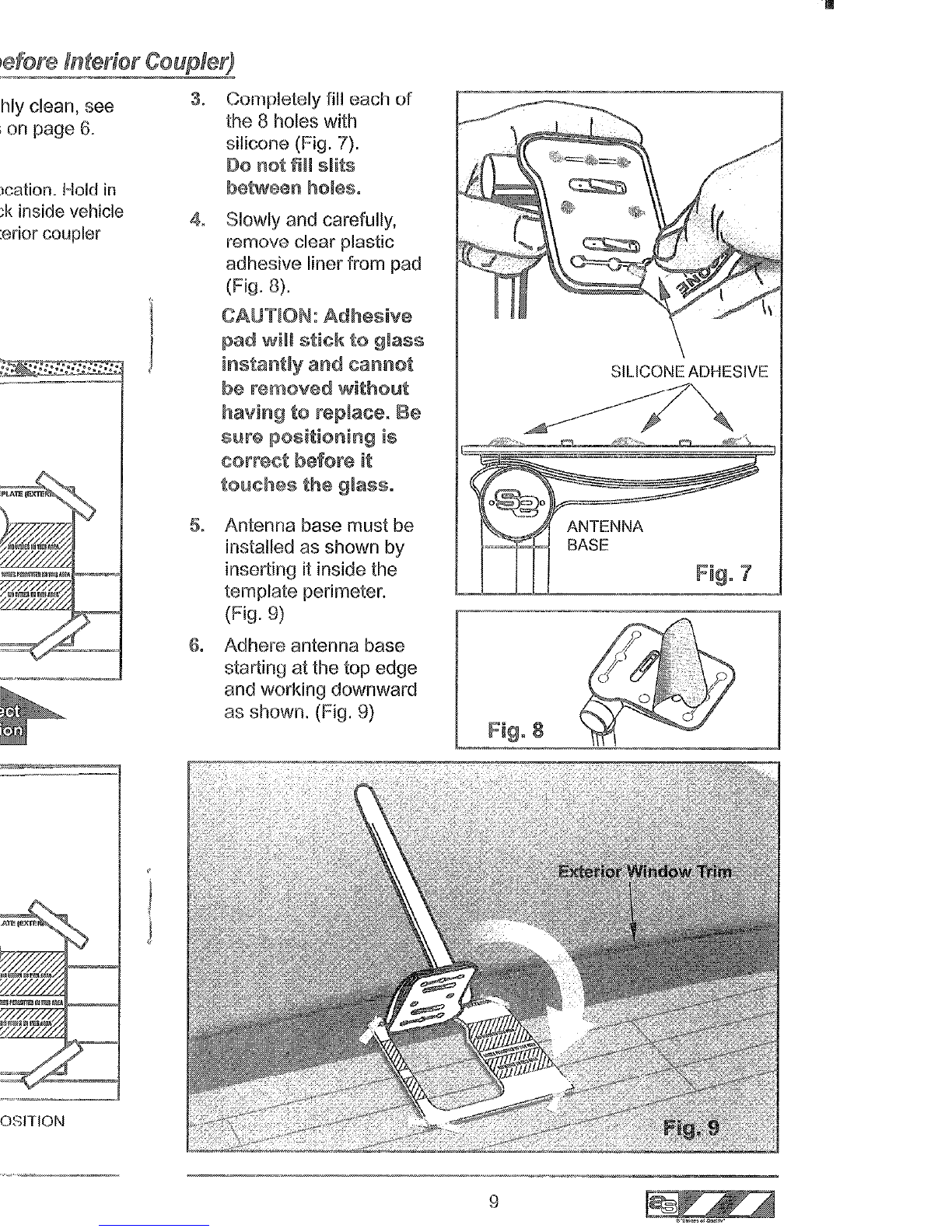
m glass using a skmdard ~ai~d~y~~.
Dor1o~usea
mercially available heat gun or other type nCtoul.
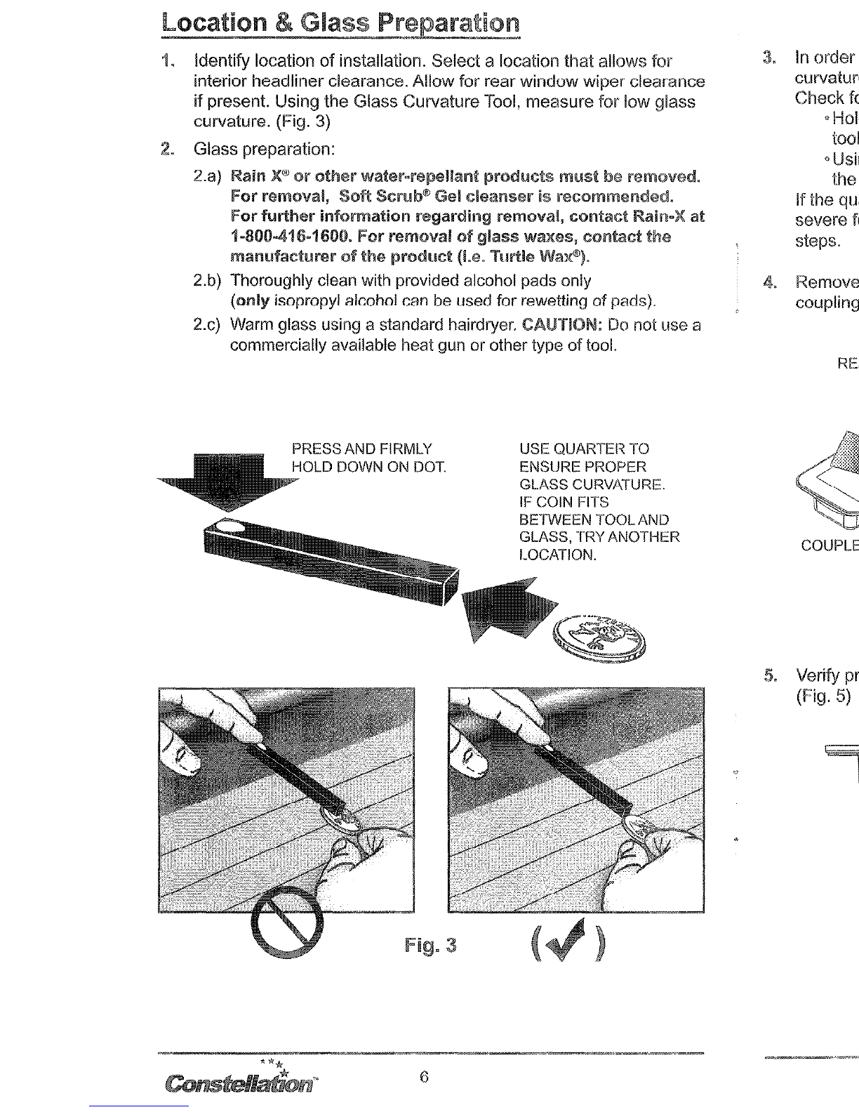
PRESSAND FIRMLY
USE QUARTER TO
OLD DOWN ON ROT. ENSURE PROPER
GLASS CURVATURE.
IF COIN FITS
BETWEEN TOOLAND
GLASS, TRY ANOTHER
LOCATION.
. In order for
adhesive
to pmperly adhere k2exterior surf333, the
cu~lature of the glass must no%be severe, for best installatian.
Check for cuwa%ureof glass using the tool provided.
~Maldtool flush against glass sutiace, wifh finger applied or&
kml dot (as shown in Fig.3).
*Using a quarter, slide i%flush along ‘rheglass sufiace toward
ahe~~~o~i~~end of the tool, as shown.
If the quarkr fits beneath the $ool(Fig. 3), the curvature is too
severe for optimal in§~~tl~~i~n.Select diffemm~location I repetat
steps.
REMOVE CAUJION LABEL ADJUSTED IN ORDER TO
MAKE CONTACT WI-l-ii GLASS
,//\
SURFACE (See
Step
5
below)
. Verify probes extend kayoed adhesive pad sutiace, as shown.
(Fig. 5)
VERIFY ~~IG~T~~R ADJUST AS
NECESSARY USING FkANGE
DEPRESSOR, BEING CAREFUL NOT
TO DAMAGE OR KINK PROBES.
3.
In
order for adhesive to properly adhere to exterior surface, the
curvature
of
the glass must not be severe, for best installation.
Check for curvature
of
glass using the tool provided.
oHold tool flush against glass surface, with finger applied onto
tool dot (as shown in Fig.3).
•Using aquarter, slide it flush along the glass surface toward
the opposite end
of
the tool, as shown.
Ifthe qUalier fits beneath the tool (Fig. 3), the curvature is too
severe for optimal installation. Select different location -repeat
steps.
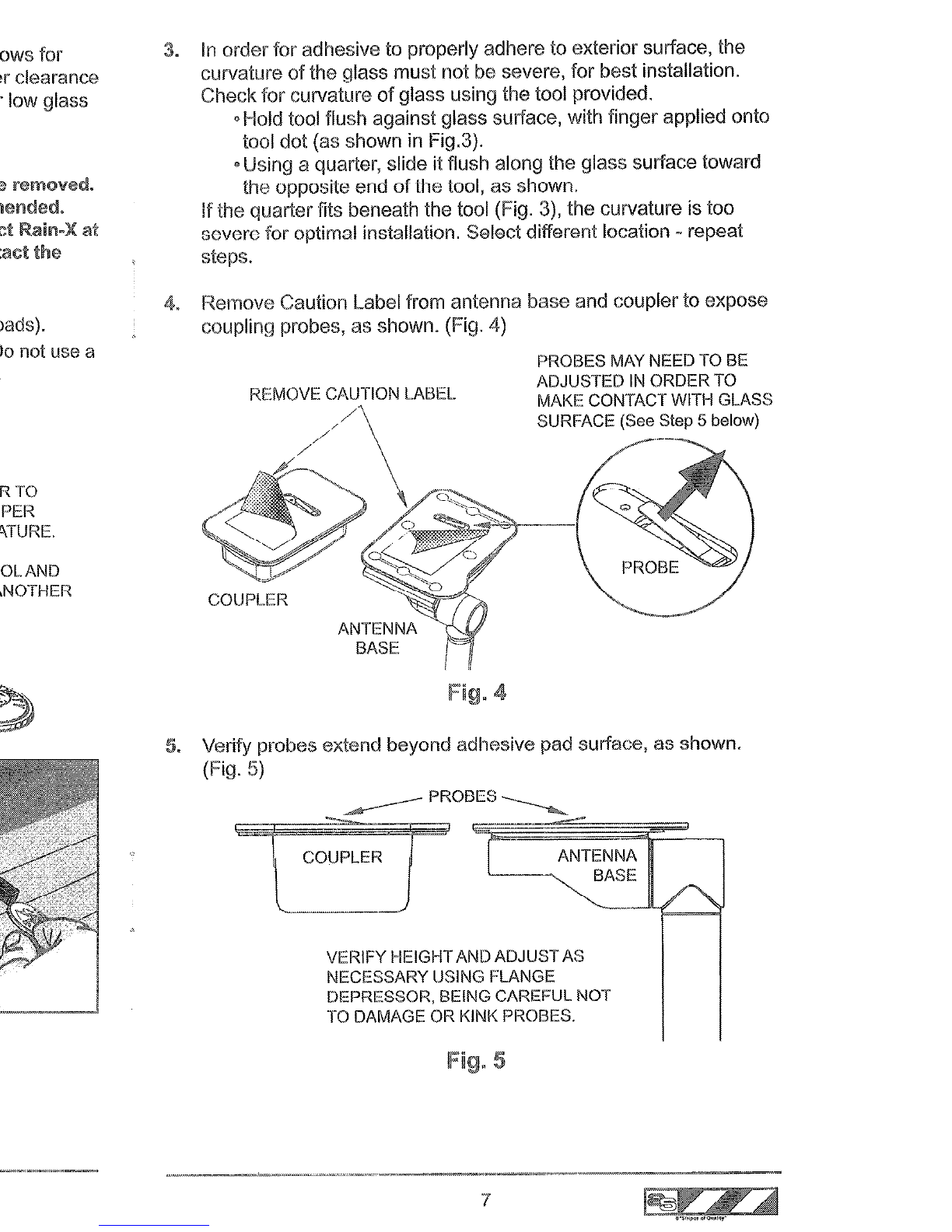
4. Remove Caution
label
from antenna base and coupler to expose
coupling probes, as shown. (Fig. 4)
PROBES MAY NEED TO BE
ADJUSTED
IN
ORDER TO
MAKE CONTACT WITH GLASS
SURFACE (See Step 5below)
I
IFig. 4
5.
Verify probes extend beyond adllesive pad surface, as shown.
(Fig.
5)
VERIFY HEIGHTAND ADJUSTAS
NECESSARY USING FLANGE
DEPRESSOR, BEING CAREFUL NOT
TO DAMAGE OR KINK PROBES.
5
7