4
Background Noise Level Test
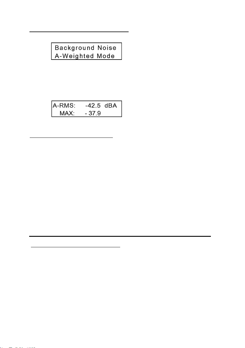
After turning the meter on it comes up in the Background Noise “A
weighted” measurement mode. The display will indicate the RMS reading
on the first line and the MAX reading on the second line. Pressing button
“B” resets the MAX reading.
How to test for background noise:
When testing a new building for background noise, turn on all lights, fans,
sound system and other electrical equipment which is normally on when
the building is in use. The loop system has usually not been installed yet.
however if you are certifying an installation this test is done without the
hearing loop system turned on.
Walk throughout the seating area where the loop system will be used,
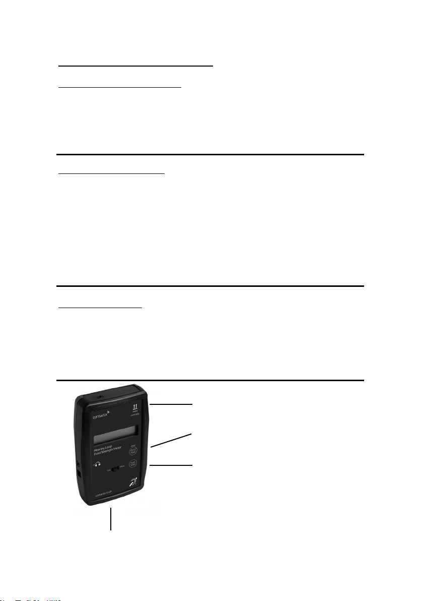
holding the meter in a vertical position at the listening plane height. The
important reading will be the MAX reading. However, it is important to
watch the RMS reading. If the MAX reading exceeds –32dBA (readings
above –32dBA will have a lower negative number, for example –30dBA
means there is more background noise than –35dBA), you will need to
document the areas where those higher noise levels are found.
IEC 60118-4 Notes and Requirements
The standard as revised in 2004 notes that any background noise level
lower than –47dBA will result in a excellent signal to noise ratio,
however levels below –32dBA are acceptable and do meet the
requirements of the standard. If the background noise level is above
–32dBA, then the building management should be notified and the
source of the interference found and repaired.
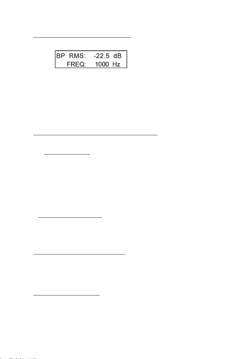
Method II - Pink noise signal Cont.
Record the RMS level readings for each of the frequencies`. As in method
I if the level does not vary by more than ±3dB the sys-tem as installed will
meet the IEC specification. This method was requested by the field
engineer so they could run the test with one instrument without
continually adjusting the frequency source. It also makes it easy to
conduct the test in more than one location.
Headphone / Full Spectrum Output
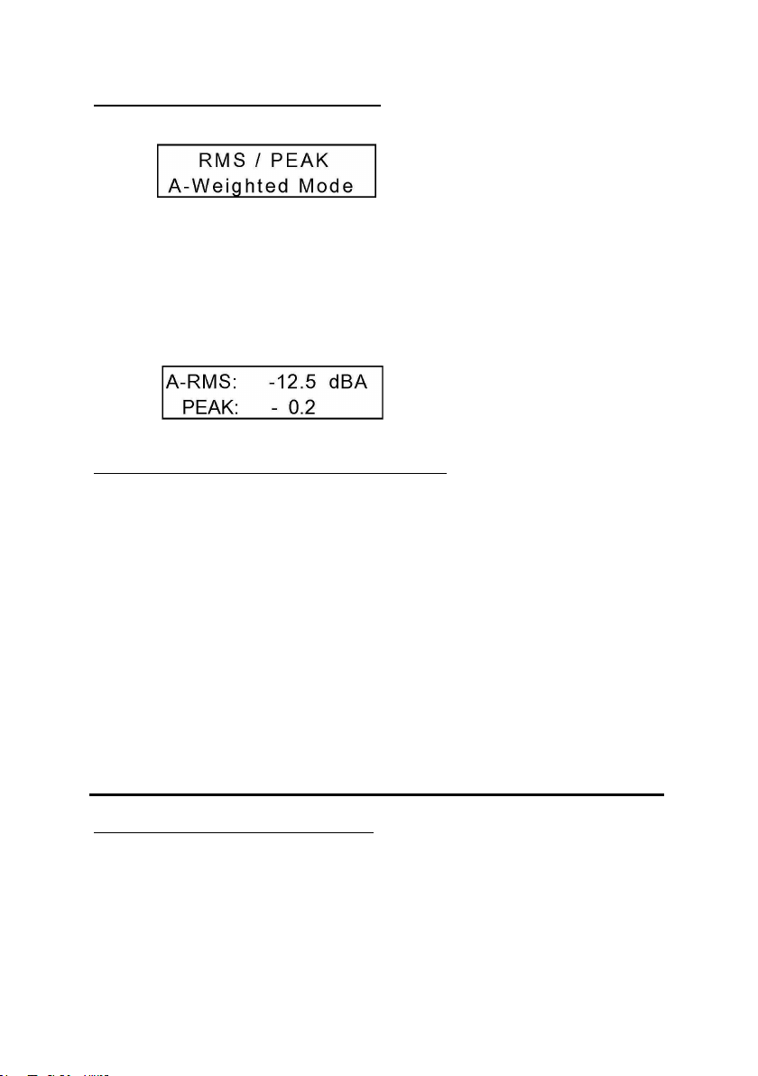
The headphone output jack serves two purposes: First it can be used to
monitor the loop program and gives you an “A Weighted” output signal
that can be listened to with standard 1/8” stereo head-phones. To change
the headphone volume slide the Use/Menu switch to Menu and use the
Mode button to advance to Headphone Volume. Pressing the Select
button advances to the volume adjust screen where the top button raises
the volume and the bottom but-ton lowers it. Once adjusted sliding the
switch back to Use will save the setting.
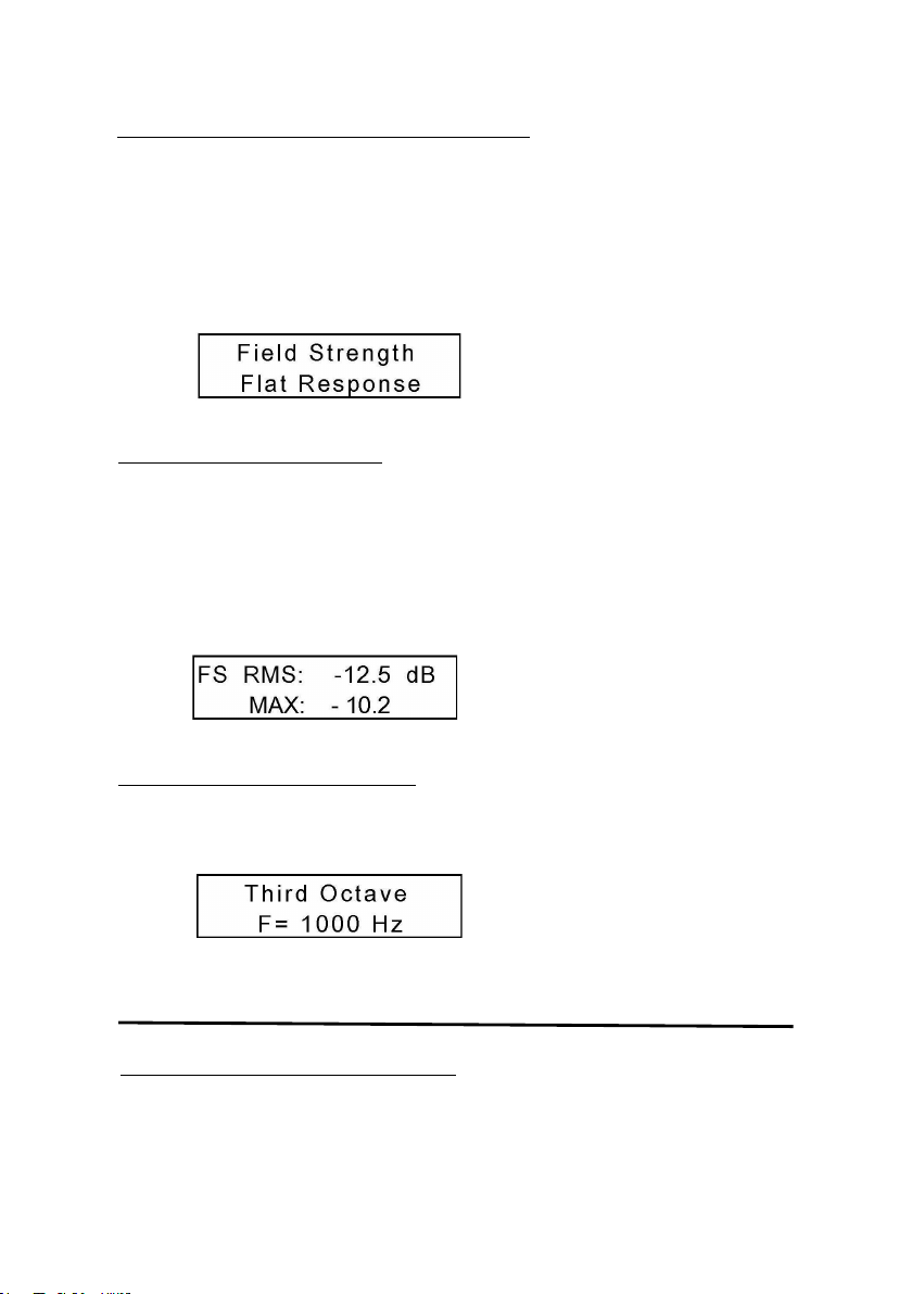
A full (flat) spectrum output can be sent from this same con-nector which
could then feed a spectrum analyzer. This would show the signal level at
the various frequencies and help to both confirm proper operation and
asses the frequency and level of any interfer-ences.
To switch from “A-Weighted” to Flat: With the meter turned on slide the
Use/Menu switch over to Menu. Press the Mode button “A” once and you
will advance to the Headphone Jack setup screen. Then pressing the
Select button “B” you can choose either A-Weighted or Flat Spectrum.
Menu Adjustments
In the Menu mode, selected by the slide switch, the following items can
be adjusted: Backlight level, headphone output type, headphone volume,
display units (dB, mG, uT), and power timeout (5 to 30, or none.
4
Background Noise Level Test
After turning the meter on it comes up in the Background Noise “A
weighted” measurement mode. The display will indicate the RMS reading
on the first line and the MAX reading on the second line. Pressing button
“B” resets the MAX reading.
How to test for background noise:
When testing a new building for background noise, turn on all lights, fans,
sound system and other electrical equipment which is normally on when
the building is in use. The loop system has usually not been installed yet.
however if you are certifying an installation this test is done without the
hearing loop system turned on.
Walk throughout the seating area where the loop system will be used,
holding the meter in a vertical position at the listening plane height. The
important reading will be the MAX reading. However, it is important to
watch the RMS reading. If the MAX reading exceeds –32dBA (readings
above –32dBA will have a lower negative number, for example –30dBA
means there is more background noise than –35dBA), you will need to
document the areas where those higher noise levels are found.
IEC 60118-4 Notes and Requirements
The standard as revised in 2004 notes that any background noise level
lower than –47dBA will result in a excellent signal to noise ratio,
however levels below –32dBA are acceptable and do meet the
requirements of the standard. If the background noise level is above
–32dBA, then the building management should be notified and the
source of the interference found and repaired.
Method II - Pink noise signal Cont.
Record the RMS level readings for each of the frequencies`. As in method
I if the level does not vary by more than ±3dB the sys-tem as installed will
meet the IEC specification. This method was requested by the field
engineer so they could run the test with one instrument without
continually adjusting the frequency source. It also makes it easy to
conduct the test in more than one location.
Headphone / Full Spectrum Output
The headphone output jack serves two purposes: First it can be used to
monitor the loop program and gives you an “A Weighted” output signal
that can be listened to with standard 1/8” stereo head-phones. To change
the headphone volume slide the Use/Menu switch to Menu and use the
Mode button to advance to Headphone Volume. Pressing the Select
button advances to the volume adjust screen where the top button raises
the volume and the bottom but-ton lowers it. Once adjusted sliding the
switch back to Use will save the setting.
A full (flat) spectrum output can be sent from this same con-nector which
could then feed a spectrum analyzer. This would show the signal level at
the various frequencies and help to both confirm proper operation and
asses the frequency and level of any interfer-ences.
To switch from “A-Weighted” to Flat: With the meter turned on slide the
Use/Menu switch over to Menu. Press the Mode button “A” once and you
will advance to the Headphone Jack setup screen. Then pressing the
Select button “B” you can choose either A-Weighted or Flat Spectrum.
Menu Adjustments
In the Menu mode, selected by the slide switch, the following items can
be adjusted: Backlight level, headphone output type, headphone volume,
display units (dB, mG, uT), and power timeout (5 to 30, or none.