5
WARNING: POTENTIAL ELECTROSTATIC CHARGING HAZARD!
When installed in hazardous locations, precautions must be taken to ensure
electrostatic charging cannot occur. Prevent unintentional contact or clean with a
dry cloth. Clean ONLY with a damp cloth. Do NOT use any solvent.
CAUTION: Always observe the applicable local standards, regulations and safety
requirements. Failure to comply with required safety precautions may result in
serious injury or damage to people/property/product and loss of all claims for
damages.
III. STORAGE
The BDI-FLX interface cable is to remain packed in the box in which it is shipped until ready for
installation. This unit should be stored in a cool dry atmosphere with ambient temperatures within
-40ºC to 50ºC
(-40ºF to 122ºF).
IV. INSTALLATION
WARNING: These installation and servicing instructions are for use by qualified personnel only.
To avoid injury and electrical shock, do not perform any servicing other than that
contained in this manual. The installation and wiring of this unit should be performed
in accordance with the latest edition of the governing Electrical Code.
WARNING: Disconnect power to the unit before wiring.
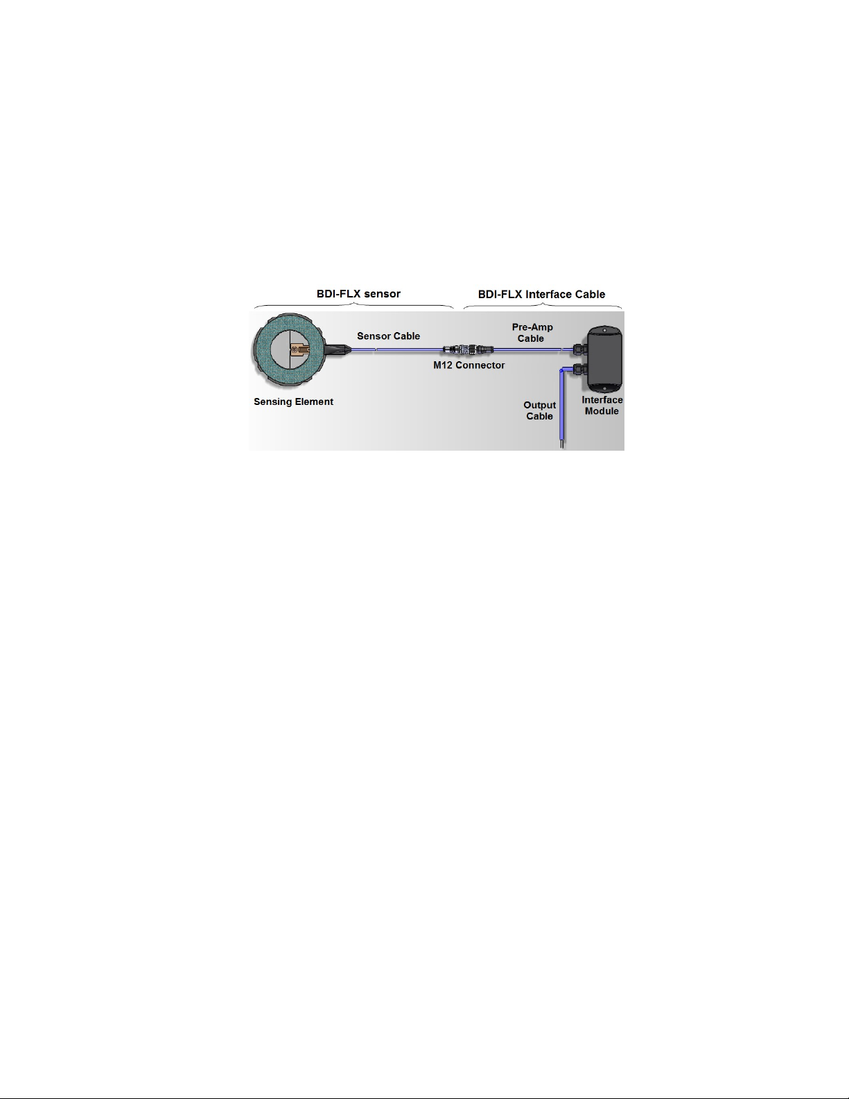
NOTE: This section describes the procedures and requirements for connecting the BDI-FLX 2W-
IS interface cable to the user’s system. For installation of the BDI-FLX sensor please
refer to “Preparation and Installation of the BDI-FLX Sensor and connection to the BDI-
FLX Interface Cable Assembly” document provided with the BDI-FLX sensor.
1. The BDI-FLX Burst Disc Sensor System is not equivalent to a traditional mechanical switch. The
user must read carefully the installation procedure for the selected model and verify that their
system meets the required conditions for the specific unit.
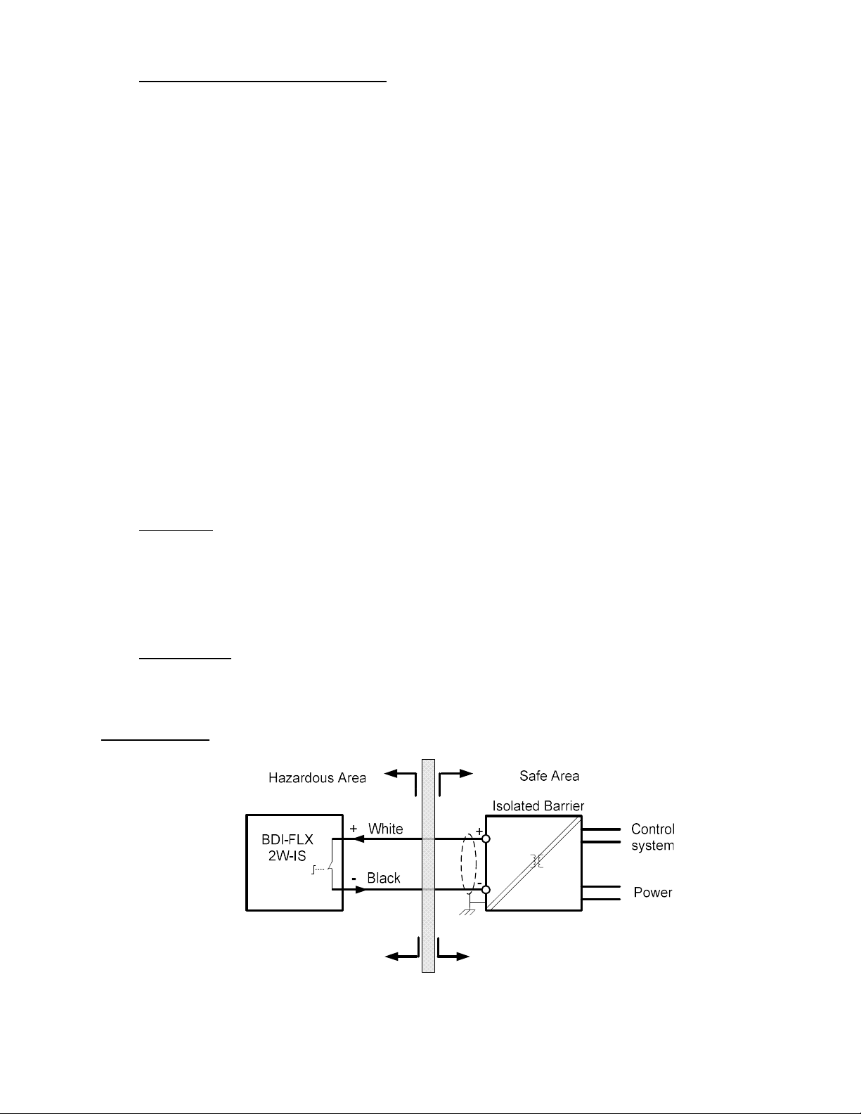
2. The BDI-FLX 2W-IS System drops a certain amount of voltage in operation, typically about 5.5 V.
This voltage drop determines how many volts the load (e.g., the safety barriers or control system
digital input channel) can obtain from the supply voltage. If the supply voltage minus the voltage
drop is not sufficient for load normal operation, the device will not turn ON. Check the receiving
system manufacturer’s specifications for the input ON voltage threshold.
3. The BDI-FLX 2W-IS System leaks a small amount of current through the loop when they output a
switching “OFF” signal. This current value is typically 0.075 mA at normal environmental condition
and will not be over 0.85 mA under specified operating conditions. The current flows through the
load and produces a small voltage across the load. If this voltage is greater than the value that will
allow it to turn ‘OFF”, the load will remain in the ON state although the sensor unit has switched
OFF. Check the manufacturer specifications for the control input OFF voltage threshold.
4. The BDI-FLX 2W-IS System output is designed as Normally Closed (ON state). Each time the unit
is powered up, the output stays OFF for about 62 ms (power-up time delay) then switches ON. This
warm-up period allows the power line to stabilize. User should examine their receiving system
power-up set time for logic adaptation.
5. The BDI-FLX Burst Disc Sensor System is designed for continuous monitoring of disc burst. When
powering up on initial installation or upon restoring power from a lost power condition, the unit will
reset itself automatically. When the BDI-FLX system trips an OFF signal as a result of a disc burst,
the user should replace the rupture disc and BDI-FLX sensor. The user can reuse the interface
cable. Re-powering the system without replacing the BDI-FLX sensor could result in a false normal
(ON) signal.