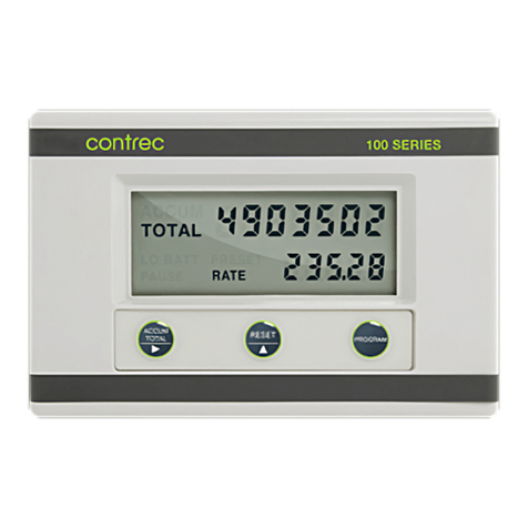
Contrec 212 User manual

212-M-V2.1
HEAT CALCULATOR
MODEL 212
June 2017

212-M-V2.1

212-M-V2.1
CONTENTS
1. Overview 3
1.1 Model Number Designation 5
1.2 Conversion Factors 6
2. Specification 7
3. Operation 11
3.1 Display Operation 13
3.1.1 Normal Operation 13
3.1.2 Charge/Discharge Operation 17
3.1.3 Peak and Off-Peak Operation 18
3.2 Checking Set-up Parameters 19
3.3 Units of Measurement 24
3.4 Frequency Cut-off 25
3.5 Offset Functions 26
3.6 Operating Modes 27
3.6.1 Heating 27
3.6.2 Cooling 27
3.6.3 Heating/Cooling 27
3.6.4 Charge/Discharge 27
3.7 Peak and Off-Peak 28
3.8 Logging 29
4. Communications 30
4.1 Meter-bus 31
4.2 Infra-red Communications Link 33
4.3 RS485 with Modbus RTU Protocol 34
4.3.1 Hardware 34
4.3.2 Protocol 34
4.3.3 Bus Address 35
4.3.4 Function Codes 36
4.3.5 Exception Response 36
4.3.6 List of Data Registers 37

212-M-V2.1
5. Set-up Mode 42
6. Input & Output Connections 48
6.1 Flowmeter Input 48
6.2 RTD Input 52
6.3 Power Supply 53
6.4 Pulse Output 54
6.5 Alarm Relay Outputs 56
6.6 4-20mA Output Option 58
7. Installation 60
7.1 Wall Mounting 60
7.2 Panel Mount Version 62
7.3 Removing the Front Panel 63
7.4 Verification Seal 65
7.5 Wiring Practices 66
7.6 Terminal Designations 68
Index 69

212-M-V2.1
Overview 3
1. OVERVIEW
The Model 212 Heat Calculator is designed to measure the energy consumed
in both heating and cooling (air conditioning) systems. The instrument is
normally supplied complete with temperature probes and power supply, and
will interface to a wide variety of flowmeters, including positive
displacement and inferential water meters, magnetic flowmeters with pulse
outputs, turbine flowmeters & paddlewheel flowmeters.
The Model 212 measures the temperature in the feed and return flow lines and
uses this information to calculate the density and enthalpy of water. By also
measuring the volume of water flowing in the system, the Model 212 will then
determine the energy used. Power is calculated as:
P = V x ᵨx (hTV - hTR)
where P = Power (W)
V = Volumetric Flow rate (m3/sec)
ᵨ= Density (kg/m3)
hTV =Specific Enthalpy (J/kg) at Feed Temperature
hTR =Specific Enthalpy (J/kg) at Return Temperature
The Model 212 is designed to be used in typical water heating or cooling
systems where pressures do not exceed 16 bars.
The temperature in both the feed and return lines is measured via two
PT100 resistance temperature devices (RTDs). For maximum accuracy, four
wire RTDs should be a matched pair, Class A to IEC 751 standard.
The Model 212 complies with OIML R75 and EN1434 standards and
includes Meter-bus and RS485 (Modbus RTU) communication links.
The Model 212 includes separate peak and off-peak registers as well as the
ability to compute charge and discharge energy in systems where heat may be
stored in underground tanks.
The Model 212 provides pulse output with programmable pulse width from 10
to 500ms.

212-M-V2.1
4 Overview
The Model 212 has a highly accurate built-in real time clock (2ppm typ) to
keep track of logging, peak-on/peak-off points, etc. In case of a power
failure, the real-time clock is able to keep running for two days with a ±1
minute accuracy, typically.
RoHS Directive: 2011/65/EU
EN 50581:2012 :- Technical documentation for the assessment of electrical and electronic
products with respect to the restriction of hazardous substances
EMC Directive: 2014/30/EU
EN61326:2013 :- Electrical equipment for measurement, control and laboratory use – EMC
requirements : Residential, Commercial & Light Industry Environment & Industrial
Environment.
Low Voltage Directive: 2014/35/EU
EN61010:2010 :- Safety requirements for electrical equipment for measurement, control and
laboratory use.
In order to comply with these standards, the wiring instructions in Section 7.5
must be followed.

212-M-V2.1
Overview 5
1.1 MODEL NUMBER DESIGNATION
Model212. 2 0 E 8 S
Mounting
Panel Mount 1
Wall Mount 2
Options
No Options 0
4-20mA Output 1
Power
12VDC Power N
European Adaptor
(220 VAC) E
UK Adaptor
(220 VAC) U
USA Adaptor
(110 VAC) A
Australian Adaptor
(240 VAC) H
Temperature Sensor
None 0
85mm pipe 8
120mm pipe 1
210mm pipe 2
Compliance
EN1434 S

212-M-V2.1
6 Overview
1.2 CONVERSION FACTORS
1 kWh = 3.600 MJ
1 MJ = 0.27778 kWh
1 m3= 1000 litres
1 US gal = 3.785 litres
1 ft3= 7.4805 US gal
1 kBTU = 1.0551 MJ
1 Ton x Hour (Refrigeration) = 12,000 BTU
1 therm = 100,000 BTU
1 Calorie = 4.1868 Joule
Note: kBTU are used on the Model 212 display and mean BTU x
1000.

212-M-V2.1
Specification 7
2. SPECIFICATION
General
Energy Display units: kWh, MWh, MJ, GJ, therm, BTU x 1000, tons x
hours or days (refrigeration), Cal, KCal, MCal.
Maximum Thermal Power: 3000 MW.
Accuracy Class: OIML R75 Class 4, EN1434.
Measurement Time: 0.5 sec time interval.
Environmental Class: EN1434 Classes A & C.
Ambient Temp Range: 0°C to 60°C.
Storage Temp Range: -20°C to 70°C.
Temperature Measurement
Type of Sensor: Pt100 to IEC 751, matched pair, Class A.
Temperature Range: -10°C to 220°C.
Temperature Difference: 1K to 200K.
Approved Temp Range: 1°C to 200°C.
Approved Temp Difference: 3K to 199K.
Measurement Time: 3 sec time interval.
Display
Type: LCD with 7 digit numeric display and 11
character
display.
Digits: 15.5mm (0.6") high.
Characters: 6mm (0.24") high.

212-M-V2.1
8 Specification
Flowmeter Input
Type: Frequency or Pulse between 0.01Hz to 20kHz.
Default low frequency cut-off is 0.25Hz.
Signal Type: Pulse, open collector, reed switch,
proximity switch or coil.
K-factor range: Programmable between 0.001 to 999,999.9
pulse per litre, m3, US gallon or ft3.
Location: In either the feed or return lines.
Temperature Sensor (RTD) Input
Sensor Type: Pt100 to IEC 751, matched pair, Class A.
Connection Type: Four wire.
Location: Two RTD inputs, one for the feed and a second
for the return lines.
Linearisation: Built in RTD linearisation.
Temperature Range: -10°C to 220°C.
RTD Cable Length: < 50m.
Pulse Out
Pulse Width: Programmable: 10, 20, 50, 100, 200 or 500ms.
Type: Open collector will sink up to 100mA.
30Vdc Maximum.
Function: Volume or Energy (scaled).
Frequency: 1 pulse every preset number of units of energy
or volume total.
Power Requirements
dc Power: 12 to 24V dc @ 100mA maximum.
ac Power: Supplied via a power adapter.

212-M-V2.1
Specification 9
Construction
Enclosure Material: ABS/Polycarbonate.
Colour: Light beige.
Protection: Sealed to IP67 (Nema 4X).
Mounting: Wall mounting or panel mounting.
Dimensions: 152mm (6.0") wide x 98mm (3.9") high x
43mm (1.7") deep.
Alarm Output (not available if 4-20mA Output Option is installed)
Type: Two solid state opto-isolated relays which
will sink up to 250mA. 30V dc maximum.
Function: High and low alarms
individually programmable as unsigned
values, for volumetric flow rate, energy
flow rate, feed temperature, return
temperature or temperature difference.
4-20mA Output Option
Function: Volumetric flowrate, energy flowrate,
feed temperature, return temperature
or temperature difference.
Output Range: 2.0mA to 22.0mA.
Linearity: 0.02% of span.
Accuracy: 0.1% of span.
Response Time: 0.5 seconds to 99%.
Maximum Output: Vdc -6V.

212-M-V2.1
10 Specification
RS485 Option
Data Transmitted: Volume and energy totals, peak power,
temperatures.
Baud rate: 300 - 9600 baud.
Parity: Odd, even or none.
Stop bits: One or two stop bits.
Bus Address: Programmable for multiple instruments on
the same bus.
Protocol: Modbus RTU.
Meter-Bus
Type: Conforms to CEN/TC176 Meter-bus standard.
Protocol: IEC 870-5.

212-M-V2.1
Operation 11
3. OPERATION
The Model 212 has three display modes:
1. Display of normal energy and flow information
This information is available by pressing the DISPLAY key.
Where appropriate Accumulated Totals can be displayed by
pressing the ACCUM TOTAL key.
2. Checking Set-up Parameters
By pressing and holding the DISPLAY key for about 5 seconds,
the instrument will enter the parameter set-up routine and
allow all set-up parameters to be checked but not changed.
The DISPLAY key is used to step through the parameter list.
3. Set-up Parameters
By removing the bottom cover strip of the instrument (see Section 7),
the set-up switch becomes visible. Pressing this switch will put the
instrument into the set-up mode, whereby all parameters can be
programmed using the DISPLAY, < and ûswitches.
The LCD display has 7 numeric digits with 11 alphanumeric characters along
the bottom. The alphanumeric characters are used to display the parameter
and units.

212-M-V2.1
12 Operation
Three key switches provide the following functions:
Displays the accumulated (non-resettable) totals
for Energy, Volume, operating time (elapsed
time) and Energy total for log entries.
Also changes digits, decimal point or units
when entering the set-up parameters. A
flashing digit, decimal point or unit will
indicate that the parameter can be changed.
If the Reset function is enabled during set-up,
the RESET key, when held for 5 seconds, will
reset all totals and the operating time.
Also increments the digit, changes decimal
point position, steps through units when
entering set-up parameters and steps through
individual log entries.
Used to change the display to the next parameter.
Also steps through display modes when held for
5 seconds.
RESET
DISPLAY
ACCUM
TOTAL

212-M-V2.1
Operation 13
3.1 DISPLAY OPERATION
3.1.1 Normal Operation
Data which can be displayed by pressing the DISPLAY key is as follows:
Default display - Energy
measured since the last reset.
Press DISPLAY Press ACCUM TOTAL
Accumulated Energy
Total (non-resettable).
Display segments test. Segments
are flashing.
Press DISPLAY
Volume of water measured through
the system since the last reset.
Press DISPLAY Press ACCUM TOTAL
Accumulated Volume
Total (non-resettable).
1 2 3 4 5 6 . 7
ENERGY KWH
7 8 9 1 0 1 . 8
ACCUM KWH
8 8 8 8.8.8.8
TEST 00.0.0.0.
1 4 3 4 . 6
VOLUME M3
6 4 3 2 6 . 5
ACCUM M3

212-M-V2.1
14 Operation
Energy flow rate.
Press DISPLAY
Volume flow rate.
Press DISPLAY
Temperature in the feed line.
Press DISPLAY
Temperature in the return line.
Press DISPLAY
Difference in temperature between the
feed and return lines.
Press DISPLAY
Peak power averaged over a 15 minute
period.
1 1 . 2
POWER KW
1 . 1 9 3
FLOW M3/H
8 0 . 6
FEED °c
7 2 . 3
RETURN °c
8 . 3
<
T K
1 1 . 6
PEAK P KW

212-M-V2.1
Operation 15
Press DISPLAY
Operating time elapsed since
the last reset.
Press DISPLAY Press ACCUM TOTAL
Accumulated operating
time (non-resettable).
Number of times the power has failed
or has been switched off to the unit
since the last reset.
Press DISPLAY
Time of day (24 hour clock).
Press DISPLAY
Date - Day - Month (SI Units)
Month - Day (US Units)
Press DISPLAY*
Time and date of the last logged
entry. Pressing the RESET key will
display the previous logged entries.
1 2 6 . 3 2
OP TM HR.MIN
1 2 6 4 3 . 3 2
ACCUM hr.min
6
supply fail
1 8-2 2
clock h-min
1 5 - 0 7
date 1998
1 4 2 3 . 0 7
tm log 1998

212-M-V2.1
16 Operation
Press ACCUM TOTAL
Energy Total of selected
log entry.
* If logging is not used, pressing the DISPLAY key will return to the
Energy display.
1 2 6 4 3 . 3 2
en log kwh

212-M-V2.1
Operation 17
3.1.2 Charge/Discharge Operation
If Charge/Discharge operation is programmed, the following display formats
will be apparent in place of the normal ENERGY display:
1 2 3 4 5 . 7 Charge Energy default display -
Charge Energy measured since
the last reset.
Press DISPLAY Press ACCUM TOTAL
Accumulated Charge
Energy Total
(non-resettable).
Discharge Energy measured since
the last reset.
Press DISPLAY Press ACCUM TOTAL
Accumulated Discharge
Energy (non-resettable).
Press DISPLAY Press ACCUM TOTAL
Display segments test. Segments
are flashing.
Press DISPLAY
For continuation of displays refer to Section 3.1.1 Normal Operation.
EN chr KWH
7 8 9 1 0 1 . 8
ACCUM KWH
8 8 8 8.8.8.8
TEST 00.0.0.0.
1 4 3 4 . 6
en dis kwh
6 4 3 2 6 . 5
ACCUM kwh

212-M-V2.1
18 Operation
3.1.3 Peak and Off-Peak Operation
If Peak and Off-Peak operation is programmed, the following display formats
will be apparent in place of the normal ENERGY display:
Peak Energy default display - Peak
Energy measured since the last reset.
Press DISPLAY Press ACCUM TOTAL
Accumulated Peak
Energy Total
(non-resettable).
Off-Peak Energy measured since the
last reset.
Press DISPLAY Press ACCUM TOTAL
Accumulated Off-Peak
Energy (non-resettable).
Display segments test. Segments are
flashing.
Press DISPLAY
For continuation of displays refer to Section 3.1.1 Normal Operation.
1 2 3 4 5 . 7
EN pk KWH
7 8 9 1 0 1 . 8
ACCUM KWH
8 8 8 8.8.8.8
TEST 00.0.0.0.
1 4 3 4 . 6
en opk kwh
6 4 3 2 6 . 5
ACCUM kwh
Table of contents
Other Contrec Measuring Instrument manuals
Contrec
Contrec 102A User manual

Contrec
Contrec 415 User manual

Contrec
Contrec 500 Series User manual

Contrec
Contrec 104D User manual

Contrec
Contrec 515 User manual

Contrec
Contrec 202A User manual
Contrec
Contrec 515 User manual

Contrec
Contrec 500 Series User manual
Contrec
Contrec 104A User manual
Contrec
Contrec 505 Series Installation manual