4-Zone Amplifier
Installation and Setup Guide
Supported Models
This installation guide covers this amplifier model:
•C4-8AMP1-B: 4-Zone Amplifier
What’s in the Box
The following hardware and software is required and included in your Control4 4-
Zone Amplifier box.
•Control4 4-Zone Amplifier
•IEC power cord
•This document
Additional Resources
The following resources are available:
•Your Control4-authorized reseller
•Control4 Web Site: http://www.control4.com/
Requirements and Specifications
•Ensure that your home network wiring is in place before starting your sys-
tem setup. The 4-Zone Amplifier is controlled through 10/100 Ethernet net-
working.
•Device must not be installed in a cabinet that is smaller than 20” wide x 20”
deep x 10” high.
Important Safety Instructions
WARNING! To avoid bodily harm, understand and follow these safety
precautions before operating the Control4 4-Zone Amplifier:
•To reduce the risk of fire or electrical shock: Do not use this apparatus near
water. Do not expose the apparatus to dripping or splashing. Do not place
objects filled with liquids near the apparatus. Do not expose this apparatus to
rain or moisture.
•Clean only with dry cloth.
•Do not block any ventilation openings. Install in accordance with the manufac-
turer’s instructions.
•Do not install near any heat sources such as radiators, heat registers, stoves,
or other apparatus (including other amplifiers) that produce heat.
•Do not defeat the safety purpose of the polarized or grounding-type plug. A
grounding-type plug has two blades and a third grounding prong. The wide
blade or the third prong are provided for your safety. If the provided plug does
not fit into your outlet, consult an electrician for replacement of the obsolete out-
let.
•Equipment must be connected to a Mains socket outlet with a protective earth-
ing connection.
AVERTISSEMENT! Pour éviter des dommages physiques, comprenez et
suivez ces mesures de sécurité avant d'actionner l'amplificateur de Control4 4-
Zone:
•Pour réduire le risque du feu ou de choc électrique : N'utilisez pas cet appareil
près de l'eau. N'exposez pas l'appareil à l'égoutture ou à l'éclaboussement. Ne
placez pas les objets remplis de liquides près de l'appareil. N'exposez pas cet
appareil à la pluie ou à l'humidité.
•Nettoyez seulement avec le tissu sec.
•Ne bloquez aucune ouverture de ventilation. Installez selon les instructions du
fabricant.
•N'installez près d'aucune source de chaleur telle que des radiateurs, des regis-
tres de la chaleur, des fourneaux, ou d'autres appareils (autres amplificateurs y
compris) cette chaleur de produit.
•Ne défaites pas le but de sûreté de la polariser ou du fondre-type prise. Un fon-
dre-type prise a deux lames et une troisième fourche fondante. La lame large
ou la troisième fourche sont données pour votre sûreté. Si la prise fournie ne
s'insère pas dans votre sortie, consultez un électricien pour le remplacement de
la sortie désuète.
•L'équipement doit être relié à une sortie de douille de forces à un raccordement
de mise à la terre protecteur.
WARNUNG! Um Köwrperverletzung zu vermeiden, verstehen Sie und folgen
Sie diese Sicherheitsanweisungen bevor Sie den Control4 4-Zone Verstärker
betreiben:
•Zu das Risiko des Feuers oder des elektrischen Schlages verringern:
Benutzen Sie diesen Apparat nicht nahe Wasser. Setzen Sie den Apparat nicht
Bratenfett oder dem Spritzen aus. Setzen Sie nicht die Gegenstände, die mit
Flüssigkeiten nahe dem Apparat gefüllt werden.Setzen Sie diesen Apparat
nicht Regen oder Feuchtigkeit aus.
•Säubern Sie nur mit trockenem Tuch.
•Blockieren Sie keine Ventilationsöffnungen. Bringen Sie in Übereinstimmung
mit den Anweisungen des Herstellers an.
•Bringen Sie nicht nahe irgendwelchen Wärmequellen wie Heizkörpern,
Hitzeregistern, Öfen oder anderen Apparaten (einschließlich andere Verstärker)
diese Erzeugnishitze an.
•VerfehlenSie nicht den Sicherheitszweck polarisiert oder der Erdenart Stecker.
Eine Erdenart Stecker hat zwei Blätter und eine dritte erdenzinke. Das breite
Blatt oder die dritte Zinke werden für Ihre Sicherheit zur Verfügung gestellt.
Wenn der zur Verfügung gestellte Stecker nicht in Ihren Anschluss passt, kon-
sultieren Sie einen Elektriker für Wiedereinbau des überholten Anschlusses.
•Ausrüstung muss an einen Hauptleitungseinfaßungsanschluß mit einem
schützenden Erdunganschluß angeschlossen werden.
CAUTION! To avoid data loss or equipment damage, understand and follow
these safety precautions before operating the Control4 4-Zone Amplifierlifier:
•To reduce the risk of fire, do not install in a cabinet that is smaller than 20” wide
x 20” deep x 10” high. If you do, the device may overheat.
•Protect the power cord from being walked on or pinched particularly at plugs,
convenience receptacles, and the point where they exit from the apparatus.
•Only use attachments/accessories specified by the manufacturer. Use only
with the cart, stand, tripod, bracket, or table specified by the manufacturer, or
sold with the apparatus.
•When a cart is used, use caution when moving the cart/apparatus combination
to avoid injury from tip-over.
•Unplug this apparatus during lightningstorms or when unused for long periods
of time.
•Refer all servicing to qualified service personnel. Servicing is required when
the apparatus have been damaged in any way, such as power-supply cord or
plug is damaged, liquid has been spilled or objects have fallen into the appara-
tus, the apparatus has been exposed to rain or moisture, does not operate nor-
mally, or has been dropped.
CAUTION! Pour éviter la perte de données ou les dommages aux
équipments, comprenez et suivezces mesures de sécurité avant d'actionner
l'amplificateur de Control4 4-Zone:
•Pour réduire le risque du feu, n'installez pas dans un coffret qui est plus petit
que 20 » x large 20 » x 10 profond » hauts. Si vous faites, le dispositif peut sur-
chauffer.
•Protégez le cordon de secteur contre être marchée dessus ou pincée en parti-
culier aux fiches, aux douilles de convenance, et au point où ils sortent de
l'appareil.
•Utilisez seulement les attachements/accessoires spécifiques par le fabricant.
Employez seulement avec le chariot, le stand, le trépied, la parenthèse, ou la
table spécifique par le fabricant, ou vendue avec l'appareil.
•Quand un chariot est utilisé, faites attention en déplaçant la combinaison de
chariot/appareil pour éviter des dommages de incliner-au-dessus de.
•Débranchez cet appareil pendant les orages defouge ou si inutilisépendant de
longues périodes.
•Référez-vous tous qui entretiennent au personnel de service qualifié. L'entre-
tien est exigé quand les appareils ont été endommagés de quelque façon,
comme puissance-fournissent la corde ou la prise est endommagée, le liquide a
été renversé ou les objets sont tombés dans l'appareil, l'appareil a été exposé à
la pluie ou à l'humidité, ne fonctionne pas normalement, ou a été lâché.
VORSICHT! Um Datenverlust oder Ausrüstungsschaden zu vermeiden,
verstehen Sie und folgen Sie diese Sicherheitsanweisungen bevor Sie den
Control4 4-Zone Verstärker betreiben:
•Um das Risiko des Feuers zu verringern, bringen Sie nicht in ein Kabinett an
das kleiner als 20“ breites x 20“ tiefes x 10“ hoch ist. Wenn Sie tun, kann die
Vorrichtung überhitzen.
•Schützen Sie das Netzanschlusskabel vor an gegangen werden oder
besonders an den Steckern, an den Hilfsaufnahmewannen und am Punkt gek-
lemmt werden, in dem sie vom Apparat herausnehmen.
•Benutzen Sie nur die Zubehöre/Zusätze, die vom Hersteller spezifiziert wer-
den. Verwenden Sie nur mit der Karre, dem Standplatz, dem Stativ, dem
Haltewinkel oder der Tabelle, die vom Hersteller spezifiziert wird oder mit dem
Apparat verkauft ist.
•Wenn eine Karre benutzt wird, Vorsicht, wenn Sie die Karren-/Apparatekombi-
nation verschieben, um Verletzung von spitzen-über zu vermeiden.
•Trennen Sie diesen Apparat während der Blitzstürme oder wenn unbenutzt, für
lange Zeitspannen der Zeit.
•Verweisen Sie alle, die auf qualifiziertes Service-Personal instandhalten. Die
Instandhaltung wird, wenn die Apparate in jeder Hinsicht beschädigt worden
sind, wie Energie-liefern Schnur angefordert, oder Stecker wird beschädigt, ist
Flüssigkeit verschüttet worden, oder Gegenstände sind in den Apparat gefallen,
ist der Apparat Regen oder Feuchtigkeit ausgesetzt worden, funktioniert nicht
normalerweise oder ist gefallen worden.
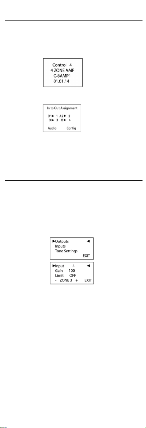
Features and Benefits
•Receives up to four stereo inputs with full audio switching on inputs.
•Outputs four stereo class D amplified channels at 60 W per channel at 8
ohms or at 120 W per channel at 4 ohms (not all channels driven simulta-
neously).
•Adjustable gain, treble, and bass for each zone
•Master Volume Control for all outputs
•Device chassis is two standard rack spaces and rack mountable using
three standard rack spaces configuring to EIA 19” rack standards. The
optional Control4 Rack Mount Kit (C4-3URMK-B) provides 1/2 U spacing
above and below the chassis. If the Control4 Rack Mount Kit is not used,
allow ½ rack space above and below the chassis for ventilation.
•Communicates via Ethernet 10/100 networking.
About the 4-Zone Amplifier
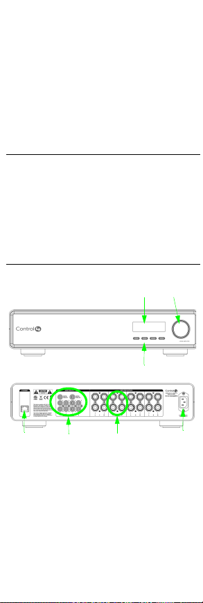
Front and Back Views
1. Front Display—LCD for displaying or setting 4-Zone Amplifier settings, navi-
gating system menus, viewing or modifying audio source routing and zone set-
tings for gain, bass, and treble, or viewing zone activity.
2. Select Dial—For scrolling through list items and options displayed on the
LCD. Press to make selections.
3. Buttons—For accessing menu options displayed on the LCD.
4. Ethernet Port—RJ-45 for a 10/100 BaseT Ethernet connection
5. Audio Inputs 1-4—Jacks for up to four audio sources. Inputs 1 and 3 can be
set up for analog or digital sources. Inputs 2 and 4 are for analog sources only.
6. Amplifier Outputs 1-4—5-way binding post pair for up to four stereo class D
amplified zones
7. Power Plug Port—For use with a standard IEC equipment power cord. Use
the supplied power cord or ensure the power cord you are using is at least 18
AWG or larger.
Install the 4-Zone Amplifier
This device operates as part of the Control4 home system, which requires
physical connections and logical connections to function as designed.
WARNING! Connecting speaker wires or input cables while the 4-Zone
Amplifier is powered, may cause shock and could damage the amplifier. Unplug
the power cord before making connections.
AVERTISSEMENT! Les fils se reliants de haut-parleur ou les câbles entrés
tandis que l'amplificateur 4-Zone est actionné, peuvent causer le choc et
pourraient endommager l'amplificateur. Débranchez le cordon de secteur avant
d'établir des rapports.
WARNUNG! Anschließenlautsprecherdrähte oder eingegebene Kabel,
während der Verstärker 4-Zone angetrieben wird, können Schlag verursachen
und konnten den Verstärker beschädigen. Trennen Sie das
Netzanschlusskabel, bevor Sie Beziehungen herstellen.
CAUTION! Do not bridge outputs. The outputs on the C4-8AMP1-B
cannot be bridged. Do not connect black terminals together or to
ground. The black terminals are not at ground potential; connecting
them together or to ground can damage the amplifier.
CAUTION! Ne jetez pas un pont sur les sorties. Les sorties sur le C4-
8AMP1-B ne peuvent pas pont. Ne mettez pas les bornes noires
ensemble ou à la terre. Les bornes noires ne sont pas au potentiel au
sol ; les mettre ensemble ou à la terre peuvent endommager
l'amplificateur.
VORSICHT! Überbrücken Sie nicht Ausgänge. Die Ausgänge auf
dem C4-8AMP1-B können nicht überbrückt werden. Schließen Sie
schwarze Anschlüß nicht zusammen oder an Boden an. Die
schwarzen Anschlüß sind nicht am Grundpotential; sie Boden
zusammen oder an anschließen kann den Verstärker beschädigen.
1. Connect up to four audio source devices (such as a controller, tuners, or CD or
tape players) to the audio input jacks.
Note: Inputs 1 and 3 can be set up for analog or digital sources.
2. Connect speakers to the audio output jacks. Tighten the binding posts to
ensure a good electrical connection to the speaker wires (even if you are using
banana plugs).
3. Use a standard 10/100 Base T Ethernet cable to connect the Ethernet port on
the amplifier to your network.
4. Connect the power cord provided to the back of the amplifier and to the power
outlet. Once the power cord is connected, the amplifier should power up.
Set Up Logical Connections
You must configure the 4-Zone Amplifier in the Composer project in order to
control, navigate, and use the amplifier as designed.
Create logical connections in Composer. For instructions, refer to the Control4
Composer Pro User Guide.
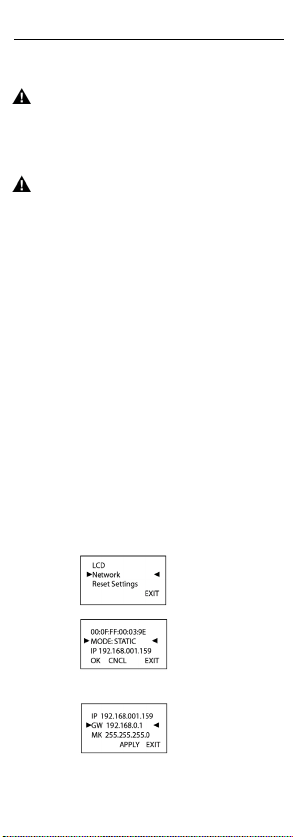
Set Network Settings
The 4-Zone Amplifier, by default, uses DHCP to obtain a network IP address.
If the local area network does not support DHCP, you can configure the switch to
use a Static IP address instead:
1. Press Config.
2. Using the Select Dial, scroll down to Network and press the Select Dial to view
the Network menu.
3. Press the Select Dial to edit your setting. Rotate the dial to choose Static IP.
4. Press OK (or press the Select Dial).
5. Edit the IP, GW, and MK fields for the Static IP network: Use the Select Dial to
select a line, then press the dial. (Scroll down to see GW and MK.)
Use the Select Dial scroll the number up or down and edit as needed, then
press the Select Dial to move to the next field within the number.
Table 1. 4-Zone Amplifier
C4-8AMP1-B 4-Zone Amplifier
Communications: Ethernet 10/100 networking
Connections: 4 stereo inputs, two of which can be digital
4 sets of amplified speaker outputs
Dimensions: 4” x 17” x 16”
Display: LCD screen
Power requirements: 100-240 VAC, 50-60 Hz
Shipping weight: approximately 16 lbs
1
3
2
4 5 6 7