Dytran 4010 User manual

Dynamic Transducers and Systems
21592 Marilla St. • Chatsworth, CA 91311 • Phone 818-700-7818
OG4010
REV A, ECN 6659, 11/21/11
REV B, ECN 9669, 03/05/13
REV C, ECN 10469, 10/16/13
REV D, ECN 11821, 03/11/15
REV E, ECN 13281, 02/28/17
OPERATING GUIDE
MODEL 4010
3-CHANNEL DC SIGNAL CONDITIONER AMPLIFIER
NOTE:
Read this manual in its entirety before operating the Model 4010 Signal Conditioner. Read all wiring and power hookup
instructions and understand the requirements prior to using another manufacturer's products with the Model 4010. Insure
that any product being interfaced with the Model 4010 is wired according to prevailing local safety and operational
standards before operating.
Included with this manual:
1) Model 4010 Specifications
2) Outline/Installation Drawing 127-4010
3) Operation
4) Wiring Information

REV E, ECN 13281 02/28/2017
2
OPERATING INSTRUCTIONS MODEL 4010 3-CHANNEL DC SIGNAL CONDITIONER AMPLIFIER
INTRODUCTION
Model 4010 is a microprocessor-controlled, 3-
Channel DC Signal Conditioner Amplifier designed to be
used with bridge type or differential output accelerometers
and pressure transducers. Model 4010 incorporates variable
gain adjustment, shunt calibration capability, and multiple
excitation level settings. For various applications where
specific frequency roll-off is required, Model 4010 has a
variety of optional 2-pole high and low pass filter modules
available for purchase under Series 4198A. See Table 1:
Optional Filters for corner frequency options. Dytran
Instruments new 3-Channel DC Signal Conditioner offers a
multitude of features in a simple bench top enclosure for
ease of use.
FRONT PANEL
REAR PANEL
DESCRIPTION
Model 4010 utilizes a microprocessor SLEEP mode
to eliminate high frequency clock noise and their
associated harmonics. The microprocessor WAKES
momentarily to acknowledge front panel switch depressions
then goes to SLEEP immediately after processing and
executing the requested function. This allows the amplifiers
to operate with minimum self generated noise and provides
clean, clock free amplified signals.
The Model 4010 uses dual 12-bit DAC's, for each
channel, to autozero the input and output amplifiers for DC
input signals. Input signals with magnitudes of +/-10 Vdc can
be zeroed. Unzeroing the amplifier zeroes both autozero
DAC's. A unique output DAC trimming routine, allows
trimming the output zero to within +/-1 mVdc. Dual 12-bit
DAC's, for each channel, are also used to set amplifier gains
from 0.00 to 999.9 with +/-0.5% precision. Amplifier gains
can be changed "on the fly" without damage to the
instrument.
Each of the 3 amplifiers has a 150 kHz full power
and a 200 kHz small signal bandwidth and can drive 10mA
into a 1 K ohm load. A filter socket is provided, for each
amplifier, to filter broadband noise. A variety of optional 2-
pole high and low pass filter modules are available for
purchase under series 4198A and can be installed in these
sockets. See Table 1: Optional Filters for corner frequency
options.
Set Vexc Switch (SW6)
Set Gain Switch (SW5)
Channel Select Switch (SW3)
Channel Select LED
Thumbwheel Switch
Setting Gain or Vexc (SW1)
Power On LED
Zero/Unzero Switch
(
SW4
)
Shunt Cal Switch
(
SW2
)
Filter In/Out Switch
CAUTION Verify fuse with proper V~
and current is installed in fuseholder
prior to applying AC Input Power.
Voltage/Rated Current/
Fuse Rating Chart
CAUTION Verify fuse with
proper V~ and current is
installed in fuseholder and
Voltage Selector switch is
properly set before turning
on Power On/Off Switch.
Power On/Off Switch
Transducer Connector
Out
p
ut BNC Connector
Voltage Selector Switch
AC Power Input
CAUTION Select Proper AC Input Voltage
before applying AC Input Power

REV E, ECN 13281 02/28/2017
3
The transducer excitation supplies are individually
adjustable for each channel from 0.00 to 12.00Vdc. Any
setting above 12.00Vdc will generate an excitation voltage of
12.10Vdc. The outputs are short circuit protected and can
supply up to 30mA each. Remote sense leads are provided
to eliminate errors caused by long cable lengths.
CE DECLARATION OF CONFORMITY -
Model 4010 has been CE tested for compliance to
EN61326-1:2013 for EMC emissions and immunity, and
EN61010-1:2010 for product safety.
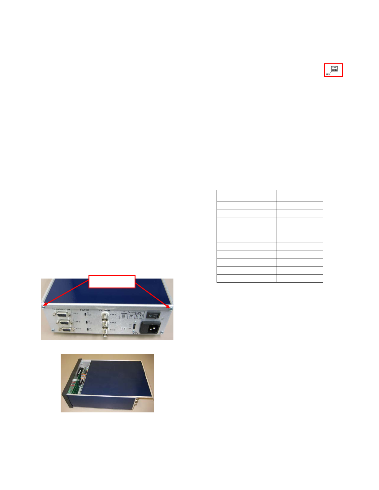
OPERATION
To operate CH1, CH2, or CH3, perform the following
steps in the sequence shown.
Step 1: Set Vexc
a) Set the Gain/Vexc Thumbwheel
Switch (SW1) to desired Vexc.
Note: If the Thumbwheel Switch is set to a value >12.00,
Vexc will be 12.10 Vdc. For 0.00 < or = Thumbwheel Switch
Setting < or = 12.00, Vexc will be equal to the Thumbwheel
Switch Setting, when selected.
b) Depress the Channel Select Switch for CH1,
CH2 or CH3. The appropriate Channel Select
LED will illuminate and stay illuminated.
c) Depress the SET Vexc Switch (SW6). The
Channel Select LED will extinguish and Vexc
for the selected channel will be set to the
Thumbwheel Switch setting.
Example: Set Thumbwheel Switch to 009.75. Depress CH2
switch, then the SET Vexc Switch. Vexc for CH2 should be
9.75Vdc +/-1%.
Step 2: Set Amplifier Gain
a) Set the Gain/Vexc Thumbwheel
Switch (SW1) to desired amplifier gain.
Note: The amplifier gain can be set anywhere from 0.00 to
999.9.
b) Depress the Channel Select Switch for CH1,
CH2, or CH3. The appropriate Channel Select
LED will illuminate and stay illuminated.
c) Depress the SET GAIN Switch (SW5). The
Channel Select LED will extinguish and the
selected channel gain will be set to the
Thumbwheel Switch setting.
Example: Set the Gain/Vexc Thumbwheel Switch to 075.00.
Depress CH2 switch, then the SET GAIN switch. CH2 gain
will be set to 75.00.
Step 3: Zero the Amplifier
a) Verify the input to the appropriate channel is
the desired input to be zeroed.
Note: Any DC input signal, within the specified operating
range of the amplifier can be zeroed.
b) Depress the Channel Select Switch CH1, CH2,
or CH3. The appropriate Channel Select LED
will illuminate and stay illuminated.
c) Depress and release the ZERO Switch (SW4).
d) The amplifier, under microprocessor control,
will first zero the output of the input amplifier,
and then zero the output of the output amplifier.
The output will be 0.00 +/- 0.050 Vdc (typ).
Step 4: Trimming the Zero output
Note: Trimming allows the user to zero the output of the
selected channel to within ±1 mVDC. This trimmed value
may then be stored in non-volatile memory and reapplied
upon power turn on.
a) Perform Step 3: Zero the Amplifier
b) Depress and hold depressed, the Channel
Select Switch for CH1, CH2 or CH3. The
appropriate Channel Select LED will illuminate
and stay illuminated.
c) To increment the output zero by 1 count of the
output zero DAC, set the Gain/Vexc
Thumbwheel Switch (SW1) to “000.01 ".
To decrement the output zero by 1 count of the
output zero DAC, set the Gain/Vexc
Thumbwheel Switch (SW1) to “001.01 ".
d) Depress the ZERO switch. The output zero will
increment or decrement by 1 count of the
output zero DAC. Successive depressions of
the ZERO switch will continue to increment or
decrement the output zero.
Note: To increment the output zero by (x) counts of the
output zero DAC, set the Gain/Vexc Thumbwheel Switch
(SW1) to “000. 0 x” and depress the ZERO switch. To
decrement the output zero by (x) counts of the output zero
DAC, set the Gain/Vexc Thumbwheel Switch (SW1) to “001.
0 x” and depress the ZERO switch.
e) To save the trimmed zero value in non-volatile
memory, depress and hold depressed the Channel
Select switch again. The selected channel LED will
extinguish. The trimmed zero value will be stored in
non-volatile memory.
Note: If any other channel is selected before the selected
channel switch is depressed and held, the trimmed zero
value will not be saved and the previously stored zero value
will be used at power up.

REV E, ECN 13281 02/28/2017
4
Unzeroing the desired channel.
Note: Unzeroing the desired channel sets both autozero
DAC's to zero. This sets the amplifier to its natural zero
position. The output of the amplifier is offset by its own offset
voltage.
Step 1: Unzero the amplifier
a) Depress the Channel Select Switch for CH1, CH2
or CH3. The appropriate Channel Select LED will
illuminate and stay illuminated.
b) Depress and hold the ZERO Switch (SW4)
until the appropriate Channel Select LED
extinguishes. The selected Channel amplifier
is unzeroed.
Applying an internal shunt calibration resistor (Rsh) to
the selected channel bridge network.
Note: Internal solder jumpers allow for a positive or negative
responding Rsh. The shunt cal resistors are removable and
may be installed by the user. Reference Location of Filter
Modules and Rsh Resistor in the figure below
WARNING: Turn Input Power Switch OFF before removing
power cable from the instrument. Remove power cable from
the instrument before disassembling any part of the
instrument.
a) Simply depress and hold the Rsh Switch for
the desired channel amplifier. The shunt cal
resistor is applied to the appropriate
transducer bridge circuit terminals for the duration
that the Rsh Switch is depressed.
Figure 1: Location of optional filter modules and Rsh Resistors.
WIRING INFORMATION
Filter Module Socket
for CH3
Filter Module Socket
for CH2
Rsh resistor for CH1
Filter Module Socket
for CH1
Note: Rsh resistor for CH2 and
CH3 are in similar location for
corresponding channel

REV E, ECN 13281 02/28/2017
5
Note: The Model 4010 Signal Ground is isolated from power
ground. This allows connecting the oscilloscope Power
Ground to the 4010 Signal Ground. To minimize high
frequency EMI susceptibility, install clamp-on ferrites with
frequency bands of 80MHz to 800MHz.
MAINTENANCE AND REPAIR
These instruments are not field repairable. If you
detect a problem with the measurement system, call the
Dytran factory to talk with one of our service engineers. If
the instrument must be returned for evaluation and/or
repair, you will be assigned an RMA (Returned Material
Authorization) number to help us track the unit through
the evaluation process.
Consult Dytran Instruments for associated cable
assemblies to mate with the Model 4010.
OPTIONAL FILTER SETUP
The Model 4010 incorporates an optional 2-pole
high pass (HP) or a 2-pole low pass (LP) Butterworth filter at
each channel. These filters are available for purchase under
Series 4198A. See Table 1: Optional Filters for corner
frequency options. The filters utilize DIP sockets that accept
DIP modules. To install the Filters:
NOTE: UNPLUG THE UNIT BEFORE INSTALLING THE
FILTERS TO AVOID THE DANGER OF ELECTRICAL
SHOCK.
1) Remove the two screws holding the top cover
in place. These two screws are located on
rear panel at the top.
2) Slide the top panel off of the assembly.
3) Locate the desired channel to be filtered.
SEE - Figure1: Location of optional filter
modules.
4) Unplug the necessary wiring to provide a
clear working area in order to install the
filters.
5) Before installing the filters.
NOTE: THE NOTCH ON THE FILTERS
INDICATE LOCATION OF PIN 1
WHICH WILL BE INSTALLED
RESPECTIVELY WITH PIN 1 ON THE
FILTER SOCKET SHOWN IN FIGURE 1.
6) Re-install unplugged wiring accordingly.
7) Re-install screws to hold top panel in place.
Do not over tighten screws.
8) Once the assembly of the filters into the
signal conditioner have been installed
activate the desired filters by flipping the
selected switch(es) on the rear panel.
Setup of the filters into Model 4010 is now complete.
OPTIONAL 4198A FILTER SERIES
Model Corner
Frequency Filter
4198A1 1kHz Low Pass 2-Pole
4198A2 5kHz Low Pass 2-Pole
4198A3 10kHz Low Pass 2-Pole
4198A4 20kHz Low Pass 2-Pole
4198A5 50kHz Low Pass 2-Pole
4198A6 100kHz Low Pass 2-Pole
4198A7 1Hz High Pass 2-Pole
4198A8 5Hz High Pass 2-Pole
4198A9 10Hz High Pass 2-Pole
4198A10 100Hz Low Pass 2-Pole
Table 1: Optional Filters.
SCREWS
Table of contents