Control Equipment GX Force User manual

BRISBANE OFFICE
1/3 Deakin Street
Brendale
QLD 4500 AUSTRALIA
PH: +61 7 3481 9000
Operating Manual
PERTH OFFICE
5/30 Enterprice Crescent
Malaga
WA 6090 AUSTRALIA
PH: +61 8 6184 7840
GX Force
Part Number: 71-0626
Released: 9/21/23
Revision: P3

WARNING
Read and understand this instruction manual before operating
instrument. Improper use of the gas monitor could result in bodily
harm or death.
Maintenance of the gas monitor is essential for proper operation
and correct readings.
Bump test the instrument before each day’s use with a known
concentration of each target gas. A bump test can be done in User
Mode’s BUMP item or by applying gas in Measuring Mode. The
instrument does not need to be calibrated unless it does not pass
the User Mode bump test or does not respond appropriately, as
defined by the user, in Measuring Mode. For more information
about bump test and calibration requirements, see IEC 60079-29-2.
Page 2 of 148
GX-Force
Operating Guide

Statement of Quality and Conformance
RKI Instruments, Inc. certifies that this instrument has been tested, inspected, and
calibrated by a qualified technician and was found to meet or exceed the
manufacturer's specifications per ISO 9001 Quality System.
Register your Product here:
www.rkiinstruments.com/registration
RKI Instruments, Inc. 33248 Central Ave, Union City, CA 94587
Phone (510) 441-5656 • (800) 754-5165 • www.rkiinstruments.com
230913/10000
GX-Force Quick Reference Guide
Scan QR code for
GX-Force Manual
GX-Force Quick Reference Guide
AIR
POWER
MODE
POWER
MODE
Press & Hold
Press & Hold
Press & Hold
Turn On
Fresh Air
Turn Off
After brief
warm-up period
Normal
Operation
Past Due Bump/CAL
POWER
MODE
AIR
To Bump / CAL
&RQ¿UP8VH
Page 3 of 148
GX-Force
Operating Guide

Table of Contents
Chapter 1: Introduction . . . . . . . . . . . . . . . . . . . . . . . . . . . . . . . . . . . . . . . . . . . . . 9
Overview
About the GX-Force
Specifications10
About this Manual
Chapter 2: Description . . . . . . . . . . . . . . . . . . . . . . . . . . . . . . . . . . . . . . . . . . . . 13
Overview
Instrument Description
Case
LCD
Control Buttons
Alarm LEDs
Buzzer
Vibrator
Printed Circuit Boards (PCBs)
Pump
Control Buttons
Sensors
Filters
USB Type-C Charging Data Port
Included Accessories
Tapered Rubber Nozzle
Belt Clip
AC Adapter Cable
Optional Accessories
USB Type-A to Type-C Cable
Saple Hose & 8 Inch Probe
External Dilution Fitting
Page 4 of 148
GX-Force
Operating Guide
15
12
13
13
13
14
15
9
10
9999
14
14
15
16
17
18
18
19
15
14
14
19
19
18
17
18

Chapter 3: Operation. . . . . . . . . . . . . . . . . . . . . . . . . . . . . . . . . . . . . . . . . . . . . . . . . . . . . . 21
Overview
Start Up
Turning On the GX-Force
Performing a Demand Zero
Turning Off the GX-Force
Measuring Mode Operation
Confirmation/Non-Compliance Indicator
Monitoring an Area
Combustible Gas Detection
Oxygen-Enriched Atmospheres
H2-Compensated CO Detection
Interference Information
Alarms
Alarm Indications
Responding to Alarms
Saving Snap Log Data
Data Logging
Chapter 4: Display Mode . . . . . . . . . . . . . . . . . . . . . . . . . . . . . . . . . . . . . . . . . . . . . . . . . . 44
Tips for Using Display Mode
LED Flashlight (LIGHT)
Peak Screen (PEAK)
STEL Screen (STEL)
TWA Screen (TWA)
Combustible Sensor Target Gas Conversion (LIST)
Turning the Pump Off (PUMP.OFF)
Changing the User ID (USER ID)
Changing the Station ID (STN ID)
Last Successful Calibration Date (CAL DATA)
Last Successful Bump Test Date (BMP.DATA)
Viewing Snap Log Data (REC.DATA)
Date, Time, and Temperature Screen (TEMP)
Viewing Alarm Settings Screen (ALARM - - P)
Page 5 of 148
GX-Force
Operating Guide
21
27
28
30
21
21
29
29
30
32
33
33
33
33
36
42
43
45
46
46
47
47
47
50
51
52
53
54
55
55
56

Chapter 5: User Mode and Calibration . . . . . . . . . . . . . . . . . . . . . . . . . . . . . . . . 58
Overview
Tips for Using User Mode
Entering User Mode
Performing a Bump Test (BUMP)
Performing a Calibration (GAS CAL)
Setting Calibration Parameters (CAL SET)
Setting Bump Test Parameters (BUMP.SET)
Alarm Settings (ALARM - - P)
Updating the Lunch Break Setting (LUNCH)
Setting the Confirmation Beep and Non-Compliance Indicator (BEEP)
Updating the Backlight Time (BL TIME)
Turning the Key Tone On/Off (KEY.TONE)
Display Mode Items (DISP.SET)
Zero Suppression (ZERO.SUP)
Zero Follower (ZERO.FLW)
Setting the Date/Time (DATE)
Turning the Password On/Off (PASS - - W)
Viewing the ROM/SUM (ROM/SUM)
Entering Measuring Mode (START)
Chapter 6: Maintenance . . . . . . . . . . . . . . . . . . . . . . . . . . . . . . . . . . . . . . . . . . 98
Overview
Troubleshooting
Instrument Cleaning
Recharging the Battery Pack
Replacing the Sensor Filters
Combustible Gas Sensor Filter
Dual CO/H2S Sensor Filter
CO-Only/H2-Compensated CO Sensor Filter
H2S-Only Sensor Filter
Replacing the Inlet Filters
Replacing the Probe Filters
Replacing a Sensor
Page 6 of 148
GX-Force
Operating Guide
58
62
63
70
63
81
83
87
90
91
93
93
94
94
94
95
95
96
97
98
98
99
99
100
100
100
100
100
102
104
105

Chapter 7: Storage . . . . . . . . . . . . . . . . . . . . . . . . . . . . . . . . . . . . . . . . . . . . . . . 107
Chapter 8: General Parts List . . . . . . . . . . . . . . . . . . . . . . . . . . . . . . . . . . . . . 108
Appendix A: Maintenance Mode . . . .. . . . . . . . . . . . . . . . . . . . . . . . . . . . . . . . 110
Overview
Tips for Using Maintenance Mode
Entering Maintenance Mode
Performing a Calibration (GAS CAL)
Performing a Gas Test (GAS TEST)
Sensor/Battery Replacement Date (SEN.DATE)
Performing a Bump Test (BUMP)
Setting Alarms to Latching or Self-Resetting (LATCH)
Turning the Alarm Silence Function On/Off (ALM.SNC)
Turning the Demand Zero Function On/Off (D.ZERO)
Turning the Auto Zero Function On/Off (A.ZERO)
Turning the ID Display Function On/Off (ID DISP)
Turning the Zero Suppression On/Off (ZERO.SUP)
Turning the Zero Follower On/Off (ZERO.FLW)
User Mode Zero Suppression (ZSUP.DISP)
User Mode Zero Follower (ZFLW.DISP)
Turning the Pump Off Display On/Off (POFF.DSP)
Setting the Date/Time (DATE)
Turning the Password On/Off (PASS - - W)
Viewing the ROM/SUM (ROM/SUM)
Performing a Flow Adjustment (FLOW.ADJ)
Performing a Default (M.DEFAULT)
Entering Measuring Mode (START)
Appendix B: Gas Select Mode. . . . . . . . . . . . . . . . . . . . . . . . . . . . . . . . . . . . . . 124
Overview
Tips for Using Gas Select Mode
Entering Gas Select Mode
Changing the Gas Combination (GAS.COMB)
Saving the Alarm Points (SAVE-AP)
Page 7 of 148
GX-Force
Operating Guide
110
112
113
114
114
115
116
117
118
118
118
119
119
119
120
120
120
120
121
122
122
122
123
124
124
125
126
129

Turning Calibration Max Span On/Off (MAX.SPAN)
Stealth and Vibrator Settings (STEALTH)
LEL Definition (CHG LEL)
Exiting Gas Select Mode (START)
Appendix C: Interference Information . . . . . . . . . . . . . . . . . . . . . . . . . . . . . . 134
ESR-A13i-H2S, H2S Detection
ESR-A13P-CO, CO Detection
ESR-A1CP-COH, H2-Compensated CO Detection
ESR-A1DP-COHS, CO Detection
ESR-A1DP-COHS, H2S Detection
WARNING:
Understand manual before operating. Substitution of components may impair
intrinsic safety. To prevent ignition of a hazardous atmosphere, batteries
must only be changed or charged in an area known to be nonhazardous.
Page 8 of 148
GX-Force
Operating Guide
130
130
131
133
134
136
138
140
142

Chapter 1: Introduction
Overview
This chapter briefly describes the GX-Force portable gas monitor. This chapter also describes the GX-
Force Operator’s Manual (this document). Table 1 at the end of this chapter lists the specifications for
the GX-Force.
About the GX-Force
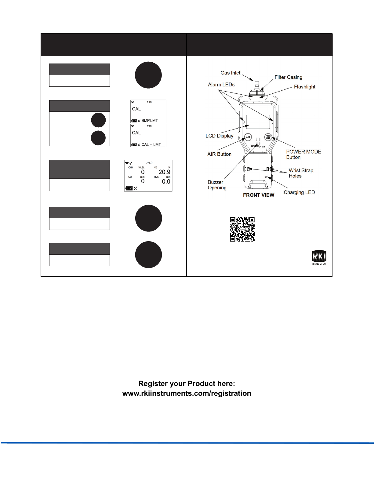
Using an advanced detection system consisting of up to three gas sensors, the GX-Force personal
four-gas monitor detects the presence of combustible gas, oxygen (O2), carbon monoxide (CO), and
hydrogen sulfide (H2S) simultaneously. The GX-Force’s compact size and easy-to-use design make it
ideally suited for a wide range of applications, including sewage treatment plants, utility manholes,
tunnels, hazardous waste sites, power stations, petrochemical refineries, mines, paper mills, drilling
rigs, and fire fighting stations. The GX-Force offers a full range of features, including:
•Simultaneous monitoring of one to four gases
•Liquid crystal display (LCD) for complete and understandable information at a glance
•Ultrabright alarm LEDs
•Distinctive audible/vibrating alarms for dangerous gas conditions and audible alarms for unit
malfunction
•Microprocessor control for reliability, ease of use, and advanced capabilities
•Data logging functions
•Alarm trend data
•STEL, TWA, and over range alarms
•Peak readings
•Built-in time function
•Lunch break feature
•CSA “C/US” classified as intrinsically safe (pending, see page 11)
WARNING: The Model GX-Force detects oxygen deficiency, elevated levels of oxygen,
combustible gases, carbon monoxide, and hydrogen sulfide, all of which can be
dangerous or life threatening. When using the GX-Force, you must follow the
instructions and warnings in this manual to assure proper and safe operation of the
unit and to minimize the risk of personal injury. Be sure to maintain and periodically
calibrate the GX-Force as described in this manual.
Page 9 of 148
GX-Force
Operating Guide

Specifications
Table 1: Standard Sensor Specifications/Alarm Points
Combustible Gas,
Methane (CH4)
Calibration Standard*
Oxygen (O2) Hydrogen
Sulfide (H2S)
Carbon
Monoxide (CO)
Detection Range 0 - 100% LEL 0 - 25% volume 0 - 100.0 ppm 0 - 500 ppm
Service Range n/a 25.1 - 40% volume 100.1 - 200.0 ppm 501 - 2,000 ppm
Reading Increment 1% LEL 0.1% volume 0.1 ppm 1 ppm
Alarm 1 5% LEL 19.5% volume,
decreasing
10.0 ppm 30 ppm
Alarm 2
10% LEL 23.5% volume,
increasing
15.0 ppm 60 ppm
STEL Alarm n/a n/a 15.0 ppm 60 ppm
TWA Alarm n/a n/a 10.0 ppm 30 ppm
*
The GX-Force is also available set up for general hydrocarbons and calibrated to a combustible gas other
thanmethane, such as isobutane. Consult Control Equipment for further information.
Table 2: GX-Force Specifications
Sampling
Method
Sample Draw
Response Time T90 within 30 seconds
Display Graphics LCD Display
Environmental
Conditions
Operating
Temperature &
Humidity
•Operating pressure: 80 - 120 kPa (80 - 110 kPa for explosion-proof classification)
•IP6 7
Continuous environment: -20°C to 50°C/Below 90% RH
Temporary environment (up to 15 minutes): -20°C to 60°C/Below 95% RH
Ambient temperature range (for charging): 10°C to 40°C
NOTE: The H2-compensated CO sensor may not effectively compensate for higher levels
of H2 if exposed to temperatures above 40°C for longer than 15 minutes. Under these
conditions, it can appear to the instrument that the H2 concentration has exceeded 2000
ppm, the max concentration that can be compensated for, resulting in a CO reading
higher than the actual CO level.
Page 10 of 148
GX-Force
Operating Guide

Safety/
Regulatory
•ATEX: Certificate Number: DNV 22 ATEX 05201X
II1G Ex da ia IIC T4 Ga (with NCR-6309)
II1G Ex ia IIC T4 Ga (without NCR-6309)
•IECEx: Certificate Number: IECEx DNV 22.0029X
Ex da ia IIC T4 Ga (with NCR-6309)
Ex ia IIC T4 Ga (without NCR-6309)
•PENDING: CSA classified, “C/US”, as Intrinsically Safe. Class I Division 1 Groups A, B, C,
D T4.
Class I, Zones 0, A/Ex da ia IIC T4 Ga (with NCR-6309)
Class I, Zones 0, A/Ex ia IIC T4 Ga (without NCR-6309)
C US
186718
Power Supply Lithium-Ion battery pack (3.6V, 300 mA)
Continuous
Operating Hours
@ 25 °C
30 hours (non-alarm operation)
Battery Charger
Input: 100 - 240 VAC, 50/60 Hz, 0.6 A
Output: 5.0 VDC, 3 A max Estimated
Charge Time: 8 hours
Case High-impact Plastic, RF-Shielded, Dust and Water Proof (IP 67)
Included
Accessories
•Belt clip
•Tapered rubber nozzle
•USB Type-C data cable
Optional
Accessories
•AC adapter
•12 VDC adapter
•10 foot hose and probe
•Hose/Probes of various lengths, see “Chapter 8: General Parts List” on page 108
•Dilution Fitting (1:1)
•Data Logger Management Program
Dimensions
and Weight
Approximately 173(H) x 64(W) x 47(D) mm (6.8” H x 2.5” W x 1.9” D)
Approximately 280 g (9.9 oz.)
Table 2: GX-Force Specifications
Page 11 of 148
GX-Force
Operating Guide

About this Manual
The GX-Force Operator’s Manual uses the following conventions for notes, cautions, and warnings.
NOTE: Describes additional or critical information.
CAUTION: Describes potential damage to equipment.
WARNING: Describes potential danger that can result in injury or death.
Page 12 of 148
GX-Force
Operating Guide

Chapter 2: Description
Overview
This chapter describes the GX-Force instrument and its accessories.
Instrument Description
Case
The GX-Force’s sturdy, high-impact plastic case is radio frequency (RF) resistant and suitable for use in
many environmental conditions, indoors and out. The case is dust-proof and water-resistant. A clear
plastic window on the front of the case allows for LCD viewing.
Four screws in each corner of the back case allow access to the sensors and filters. Three threaded inserts
on the back of the case allow for installation of a belt clip.
Figure 1: Component Location
LCD Display
Charging LED
Gas Outlet
Gas Inlet
AIR Button
Alarm LEDs
Filter Casing
POWER MODE
Button
Flashlight
Buzzer
Opening
Wrist Strap
Holes
FRONT VIEW
BACK VIEW
Page 13 of 148
GX-Force
Operating Guide

LCD
The digital LCD (liquid crystal display) simultaneously shows the gas reading for all installed sensors.
The LCD also shows information for each of the GX-Force’s operating modes.
WARNING: A thin protective film covers the display to prevent scratches during shipping.
Remove this film before use. Leaving the film installed voids the intrinsically safe
certification.
Control Buttons
Two control buttons, AIR and POWER MODE, are located below the LCD.
Flashlight LED
A white LED is visible through a round, raised, frosted lens in the top of the case. This LED can be used
to provide extra light, if necessary. The flashlight can be activated in the Display Mode. See page 46 for
activating and deactivating the flashlight LED.
Alarm LEDs
The six alarm LEDs around the edge of the case alert you to gas, low battery, and failure alarms.
Table 3: GX-Force Control Button Functions
Button Function(s)
AIR •turns on LCD backlight
•resets alarm condition if LATCH is set to ON in Maintenance Mode
•enters User Mode, Maintenance Mode, and Gas Select Mode when
used with POWER MODE button
•activates the demand zero function (adjusts the GX-Force’s fresh
air reading)
•changes the value of a parameter available for adjustment
•scrolls through parameter options
POWER MODE •turns the GX-Force on and off
•turns on LCD backlight
•enters and scrolls through Display Mode
•enters instructions into the GX-Force’s microprocessor
•resets alarm condition if LATCH is set to ON in Maintenance Mode
•enters User Mode, Maintenance Mode, and Gas Select Mode
when used with AIR button
Page 14 of 148
GX-Force
Operating Guide

Charging Indicator LED
One LED located near the bottom of the instrument lights up green when a power cable is plugged into
the instrument’s charging/data port. The LED changes to orange as charging begins. When charging is
complete, the LED turns green until the instrument is disconnected from power.
Buzzer
One solid-state electronic buzzer is located inside the case. Sound exits the case through a hole
in the middle front of the case. The buzzer sounds for gas alarms, malfunctions, low battery
voltage, and as an indicator during use of the GX-Force’s many display and adjustment options.
Vibrator
A vibrating motor inside the GX-Force case vibrates for gas alarms, unit malfunctions, and as an
indicator during normal use of the various modes of the GX-Force.
NOTE: If STEALTH is set to ON, the vibrator only functions when VIB in the STEALTH Gas
Select Mode item is set to ON. See “Stealth and Vibrator Settings (STEALTH)” on
page 130.
Printed Circuit Boards (PCBs)
The GX-Force’s printed circuit boards analyze, record, control, store, and display the information
collected. The circuit boards are located inside the case. They are not user serviceable.
Pump
A diaphragm pump inside the GX-Force draws the sample to the sensors. It can draw sample from as far
as 100 feet from the GX-Force. The pump is not user serviceable.
CAUTION: Sample hose lengths of more than 100 feet are not recommended for the GX-Force
because of flow rate reduction.
Flow Chamber
The flow chamber is on the back of the GX-Force and is held in place by four Phillips screws. The flow
chamber seals to the rubber sensor gasket which seals to the sensor faces inside the GX-Force and
routes flow from the pump to the sensors and to the exhaust port (on the back of the GX-Force case).
Sensors
The GX-Force uses three sensors to monitor combustible gas, oxygen (O2), carbon monoxide (CO), and
hydrogen sulfide (H2S) simultaneously. The sensors are located inside the GX-Force and are held in their
sockets by the sensor retainer and back case. The sensors use different
detection principles, described in the following sections.
Page 15 of 148
GX-Force
Operating Guide

Combustible Gas Sensor
The combustible gas sensor (NCR-6309) detects combustible gas in the %LEL range using 2 catalytic
elements: a standard element and a poison-resistant element that is resistant to sensor poisons like
silicone. The element’s electrical resistance changes based on the reaction of gas with oxygen. The
change in resistance affects the current flowing through the element. The GX-Force’s circuitry amplifies
the current, converts the current to a gas concentration, and displays the concentration on the LCD.
The standard calibration for the combustible gas sensor is to methane, but the sensor will still detect
and respond to a variety of combustible gases.
O2/CO/H2S Sensors
The O2, CO, and H2S sensors are electrochemical cells that consist of two precious metal electrodes in a
dilute acid electrolyte. A gas permeable membrane covers the sensor face and allows gas to diffuse into
the electrolyte. The gas reacts in the sensor and produces a current proportional to the concentration
of the target gas. The GX-Force’s circuitry amplifies the current, converts the current to a gas
concentration, and displays the concentration on the LCD.
There are 4 different types of CO and H2S sensors available:
•CO-only (ESR-A13P-CO): A single electrochemical cell that detects CO. Instruments with this
sensor cannot detect H2S.
•H2-compensated CO (ESR-A1CP-CO-H): A single electrochemical cell that detects CO. This sensor
does not respond to or responds minimally to hydrogen (displays H2 RICH once H2 concentration
reaches 2000 ppm). Instruments with this sensor cannot detect H2S.
•H2S only (ESR-A13i-H2S): A single electrochemical cell that detects H2S. Instruments with this
sensor cannot detect CO.
•CO/H2S (ESR-A1DR-COHS): A combination electrochemical cell that detects both CO and H2S.
Dummy Sensors
A dummy sensor is installed in any units that have less than 3 sensors. Dummy sensors are factory
installed. The flat side of the dummy sensor faces away from the GX-Force and the hollow side faces
toward the GX-Force.
Filters
Combustible Gas Sensor H2S Removal Filter Disk (Dark Red)
An H2S removal filter disk is placed into a recess in the filter gasket over the combustible gas sensor.
The filter disk prolongs the life of the combustible gas sensor by preventing H2S in the ambient air from
reaching the sensor. The H2S filter disk is dark red in colour and although it may darken over time, its
colour is not indicative of remaining filter life.
The H2S filter disk needs replacing once it’s been exposed to 33 ppm hours of H2S. This means the filter
needs replacing after 80 minutes of exposure to 25 ppm H2S which equates to 40, 2-minute calibrations
with a cylinder containing 25 ppm H2S. If H2S exists in the monitoring environment, the H2S filter disk
will have to be replaced more frequently.
Page 16 of 148
GX-Force
Operating Guide

CO/H2S Sensor Dual Filter (Black and White)
A dual filter is placed into a recess in the filter gasket over the dual CO/H2S sensor. The black half is a
charcoal filter for the CO sensor. The white half is a humidity filter for the H2S sensor. Replace the
filter if you notice the following:
•Unexplained CO readings
•For users with a 1 ppm H2S alarm setpoint, the filter should be replaced every 6 months, if you
notice a drift on the H2S zero reading, unexplained H2S readings, or if the filter appears dirty
(whichever is sooner).
CO-Only and H2-Compensated CO Sensor Charcoal Filter (Black)
A black charcoal filter is placed into a recess in the filter gasket over the CO sensor. The charcoal
filter disk scrubs H2S and certain hydrocarbons out of the sample to avoid false CO readings. If false or
elevated CO readings are noticed, especially in the presence of H2S, change the charcoal filter.
H2S Sensor Humidity Filter (White)
A white humidity filter covers the H2S sensor. The filter absorbs humidity in the sampling environment
to prevent unstable readings around 0 ppm H2S. For users with a 1 ppm H2S alarm setpoint, the filter
should be replaced every 6 months, if you notice a drift on the zero reading, or if the filter appears
dirty (whichever is sooner). For users with a 2 ppm or higher H2S setpoint, the filter does not
necessarily need to be replaced.
Inlet Filter Holder
The filter holder is a clear plastic dome-shaped piece on the top of the case. A male quick connect
fitting is located on the inlet filter holder. This is the GX-Force’s inlet fitting. The filter holder may be
removed by turning it counter clockwise and pulling it away from the case. One flat membrane disk
hydrophobic filter, a wire mesh disk, and a rubber filter retaining gasket are held in place by the filter
holder and are located in the bottom of the case chamber where the filter holder is installed.
Exhaust
Sample gas flows from the sensors to the exhaust port on the back of the GX-Force.
USB Type-C Data/Charging Port and Protective Cover
A USB Type-C port is located on the bottom of the GX-Force, protected by a rubber cover. Pry off this
cover when plugging in a USB Type-C cable (for charging or data transfer). A USB Type-C adapter cable
can be connected to a computer’s USB port to transfer data to the GX-Force Data Logger Management
Program.
See the GX-Force Data Logger Management Program Operator’s Manual for downloading instructions.
Page 17 of 148
GX-Force
Operating Guide

Battery Pack
A Lithium-Ion (Li-ion) battery pack powers the GX-Force. At 25°C, the battery lasts at least 30 hours. The
battery icon in the lower left corner of the LCD shows remaining battery life.
A low battery warning activates when the GX-Force detects a low battery voltage. The GX-Force sounds
a dead battery alarm when battery voltage is too low for Measuring Mode.
The battery pack can be recharged using an AC or DC charger.
NOTE: Use of batteries or battery chargers not specified by Control Equipment will
compromise the CSA classification and may void the warranty. See “Recharging the
Lithium-Ion Battery Pack” on page 99.
WARNING: To prevent ignition of a hazardous atmosphere, batteries must only be charged in
an area known to be nonhazardous.
AVERTISSEMENT: Pour éviter l'inflammation d'une atmosphère dangereuse, les batteries
ne doivent être chargées que dans une zone connue pour être non
dangereuse.
Included Accessories
Included accessories consist of the tapered rubber nozzle, belt clip, and USB Type-A to Type-C data
cable.
Tapered Rubber Nozzle
A cone-shaped 4-inch long rubber nozzle is included with the GX-Force as standard. It can be
installed on the inlet fitting by pushing the larger end over it. The smaller end can be inserted
through a hole in a wall or some other access to an enclosed area to sample the environment.
Belt Clip
The belt clip can be mounted to the back of the case using 3 Phillips head screws. The belt clip
allows the GX-Force to be securely attached to clothing or a belt.
AC Adapter Cable
The charging cable is a 4 foot cable with an AC adapter on one end and a USB Type-C charging plug
that connects to the GX-Force on the other end.
Page 18 of 148
GX-Force
Operating Guide

Optional Accessories
Several other accessories are available for the GX-Force.
USB Type-A to USB Type-C Cable
The USB cable can be ordered for connecting the GX-Force to a computer when using the GX-Force
Data Logger Management Program.
CAUTION: Sample hose lengths of more than 100 feet are not recommended for the GX-Force
because of flow rate reduction.
Figure 3: Sample Hose and Probe
Sample Hose & 8-Inch Probe
A sample hose and probe can be ordered with the GX-Force. When desired, the rubber nozzle may be
removed and the sample hose and 8-inch probe may be connected to the inlet fitting. Sample hose
lengths are available from 3 feet to 100 feet (see “Chapter 8: General Parts List” on page 108). The quick
connect end of the sample hose connects to the inlet fitting of the GX-Force and the probe screws onto
the end of the hose with the threaded fitting.
Page 19 of 148
GX-Force
Operating Guide
Figure 2: AC Adapter (USB Type-C)
NOTE: The USB Type A to Type C cable should not be used to charge the instrument. Its
intended function is to communicate with the GX-Force Data Logger Management
Program.

External Dilution Fitting
A 1:1 external dilution fitting is available for the GX-Force. It is designed to mate with the inlet fitting
and accept a sample hose and probe. The fitting is made with brass and nickel plated brass and is
appropriate for use with the four standard gases. The fitting is normally used when it is necessary to
introduce air into a sample that has no oxygen or a very low level of oxygen, such as a nitrogen-purged
sample. It can also be used when one of the target gas levels in the sample area will likely be present
in a concentration above the detection range for that gas. Since the fitting partially consists of
unplated brass, it is not appropriate for detection of elevated levels of H2S.
Figure 4: 1:1 Dilution Fitting
Page 20 of 148
GX-Force
Operating Guide
Table of contents
Other Control Equipment Gas Detector manuals