LP-10/10BP/20BP/30BP/60BP/100BP
4
1. INTRODUCTION
The use of demineralised water is recommended with Contronics humidiers for the
following reasons:
- Any minerals, salts and bacteria that enter the humidier will cause the water
reservoir to become polluted. The integrated ushing programme will delay this
process but will not prevent it entirely.
Depending on the quality of the added water, the water reservoir will eventually
become blocked. As a result, the energy of the transducers will no
longer be effective, and they will wear out more quickly. In addition, the oat
switch could transmit the wrong information to the electronics system, thereby
causing damage to the electronics.
- The minerals and salts (calcium) present in the water will end up in the area to be
humidied and could cause annoying deposits of dust.
- Any bacteria present in the water (Legionella) could multiply easily in the relatively
warm water in the tank and could thereby constitute a health hazard.
The use of demineralised water reduces:
- Maintenance
- Wear and tear to the transducers
- Deposits of dust in the area
- Bacterial growth
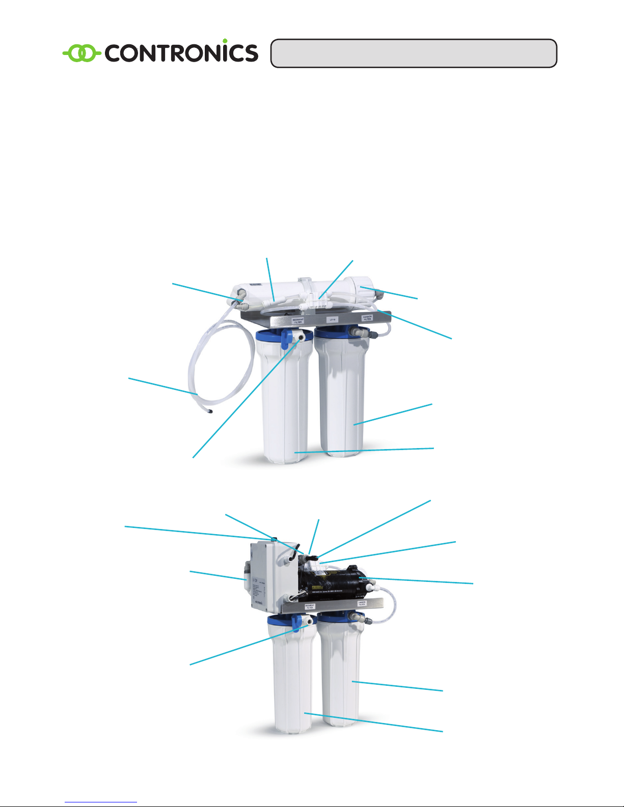
System components
The Contronics LP series is tted with a high-quality (Dow Chemical) membrane.
Working on the principle of Reverse Osmosis (R.O.), the membrane only allows water
molecules to pass through. A ushing system prevents clogging, increases the service
life of the membrane and improves performance.
Systems can be supplied with a capacity of 375 – 3,600 l per day (at a temperature of
25°C and depending on the water pressure).
Two preliminary lters are positioned ahead of the membrane: a 5 micron pre-lter and
an active carbon lter.
In the BP version, an electric pump has been added to increase the capacity in order to
cope with low water pressure or higher consumption.
The system also incorporates an automatic shut-off valve. When the system does not
need to supply demineralised water and is at the correct pressure, this will ensure that
the supply water will be shut off in order to prevent water from being unnecessarily
wasted through ushing.
A buffer tank is also included in the delivery (including the T-piece connector) and must
be tted in the supply line to the humidier. This tank will supply additional water
whenever the humidier is consuming more than the osmosis system is able to supply.
This occurs during ushing and lling. At any other time, the system supplies more
than the required consumption and any excess water will be used to top-up the tank.
The tank incorporates a rubber bag in which the demineralised water is stored. The air