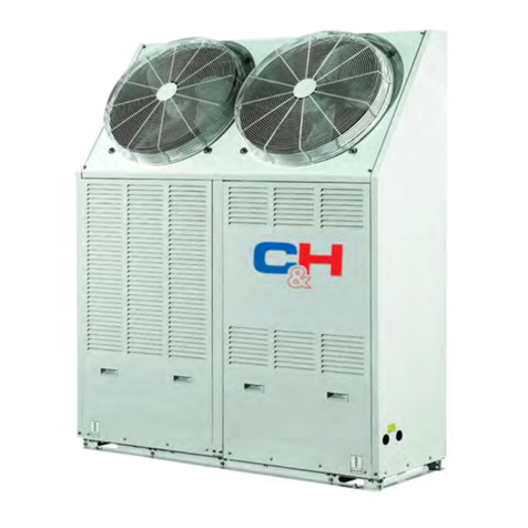
Cooper & Hunter CH-FK18SWK2 Operating instructions

UUltra-thin
Water Fan Coil
CH-FK18SWK2
CH-FK25SWK2
CH-FK34SWK2
Ultra-thin Water Fan Coil


CONTENT
1.Preface
2.Safety precautions
Warning
Attention
Specifications
Working condition
3.3 Overall dimensions
The working principle of units
3.5 Unit characteristics
Installation
Installation precautions
Positioning the unit
Minimum installation distances
Usage
Function description of wire controller
Usage of wire controller
Maintenance and Overhaul
Maintenance
Common fault and the solving methods
Appendix
Net control diagram
7.2
2.1 Mark Notes
2.2 Icon Notes
2.3
2.4
3
3.1 Parameter list
3.2
3.4
4
4.1
4.2
4.3
4.4
5
5.1
5.2
6
6.1
6.2
7
7.1
Hydraulic connections
PCB I/O port
1
2
2
2
2
3
4
4
5
6
6
7
7
7
7
10
13
13
22
21
20
20
14
22
4
22

Thank you for choosing vertical water fan coil for controlling the climate in your home.
The products strictly comply with design and production standards to provide high quality
operation, perfect performance, high reliability and good adaptability.
All repair or maintenance interventions must be performed by
the technical service department or by professionally qualified personnel. Do not modify or
intervene on the appliance as this could create dangerous situations and the manufacturer will
not be responsible for any damage caused.
al technical
1.1Failure to comply with these recommendations will invalidate the warranty.
● appliances must be installed by an authorized installer.
●All repair or maintenance interventions must be performed by the technical service
department or by professionally qualified personnel.
●All repair or maintenance interventions must be performed in specified
period and times.
●.
1.2 In case of water leaks, turn the master switch of the system to "OFF" and close the water
taps. As soon as possible, call technical service department or else
professionally qualified personnel and do not intervene personally on the appliance.
If the unit is not used for a long time, you should:
●Power off the unit.
●If there is no anti-freeze protection, please drain out the water.
1.3 Note:
●If the room temperature is too low it is damaging for the health and is also a useless
waste of energy.
●Avoid prolonged contact with the direct air flow.
●Do not leave the room closed for long periods. Periodically open the windows to ensure a
correct change of air.
1.4 Packing list
Please read this installation and maintenance manual carefully before installing and
starting up the appliance.
This instruction must be kept carefully and must always accompany the appliance. If it is
lost or damaged, please contact the loc the manufacturer service centre.
This
the manufacturer
Use genuine standard spare parts the manufacturer
the manufacturer
1.Preface
1
PFP 模板代号:
水管管孔预留区域
沿此线折90℃ 沿此线折90℃
水平检查线
2-Φ8 定位孔
从定位孔的中心到机器最高
165mm
冷凝排水管
机器底部
安装025~100的型号,必须确保两
个模板的间距是按表格的要求。
出出水
水管管管管孔孔
90°
此处与地面平齐
水平检查线
从定位孔的中心到机器最高
165mm
机器底部
安装025~100的型号,必须确保两
个模板的间距是按表格的要求。
型号
025
040
060
080
100
模板间距(mm)
0
200
400
600
800
90°
型号
025
040
060
080
100
模板间距(mm)
0
200
400
600
800
2-Φ8 定位孔
此处与地面平齐
进水管管孔
进水管管孔
TEMP
MODE FAN
ON/OFF
PM
10:50 0 00
UNIVERSAL A/C REMOTE
Screw cap
Vertical Wat er F an C oi l
INSTALLATION AND MAINTENANCE
MANUAL
electrothermal
3-way valve( )optional
Feet
(optional)
Screw
Toggle bolts
Brackets
Remote controller
optional( )
Installation Template
Vertical Water Fan Coil
Fig.1
Manual
Drain Pipe
Bellows
(optional)

2
2. Safety precaution
To prevent the users and others from the harm of this unit, and avoid damage on the unit or
other property, please use the heat pump properly, please read this manual carefully and
understand the following information correctly.
Mark Meaning
A wrong operation may lead to death or heavy injury on people.
A wrong operation may lead to harm on people or loss of material.
WARING
ATTENTION
INSTALLATION
PROFESSIONAL
INSTALLER IS REQUIRED.
EARTHING
IS REQUIRED.
Icon Meaning
Prohibition. What is prohibited will be nearby this icon.
Compulsory implement. The listed action need to be taken.
ATTENTION(include WARNING)
Please pay attention to what is indicated.
Do not put fingers or others into the fans and evaporator of the unit,
otherwise harm may be occurred.
OPERATION
PROHIBITION
SHUT OFF
THE POWER
When the heat pump need to be moved or installed again, please entrust
dealer or qualified person to carry it out. Improper installation will lead to
water leakage, electrical shock, injury or fire.
It is prohibited to repair the unit by the user himself, otherwise electrical
shock or fire may be occur.
When the heat pump need to be repaired, please entrust dealer or qualified
person to carry it out. Improper movement or repair on the unit will lead to
water leakage, electrical shock, injury or fire.
MOVE AND REPAIR
ENTRUST
ENTRUST
PROHIBIT
2.1 Mark Notes
(1) The injury means no need to be in hospital and cure for a long time.
(2) The material lost means property and datum lost.
2.2 Icon Notes
2.3 n War ing
When there is something wrong or strange smell, the power supply need
to be shut off to stop the unit. Continue to run may cause electrical
shock or fire.
Entrust a specialized personnel for installation,Improper installation
will lead to water leakage, electrical shock, injury or fire.
Be sure the unit is properly grounded, or it may lead to eletric shock.

2.Safety precaution
3
Warning:
INSTALLATION
Fix the unit
Need circuit breaker
Make sure that there is circuit breaker for the unit, lack of
circuit breaker can lead to electrical shock or fire.
Prohibit
Please use the suitable fuse.
If use copper or icon, it will cause failure, even the fire.
主 体 的 安 装
OPERATION
Check the installation
basement
Switch off the unit
Please check the installation basement regularly to avoid
any decline or damage on the basement, which may hurt
people or damage the unit.
Please switch off the power for clean or maintenance.
Make sure that the basement of the heat pump is strong
enough to avoid any decline or fall down of the unit.
Meaning
Meaning
2.4 Attention
To be installed and wired by Qualified personnel asper national electriccode.
This appliance can used by children aged from 8 years and above and persons with reduced
physical, sensory or mental capabilities or lack of experience and knowledge if they have
been given supervision or instruction concerning use of the appliance in a safe way and
understand the hazards involved. Children shall not play with the appliance .Cleaning and
user maintenance shall not be made by children without supervision.
Remember that some fundamental safety rules should be followed when using a product that
uses electricity and water, such as:
It is forbidden to touch the appliance with wet hands or body when barefoot.
It is forbidden to carry out any cleaning before having disconnected the appliances from the
electricity mains supply by turning the system master switch to OFF.
It is forbidden to modify the safety or adjustment devices or adjust without authorization and
indication of the manufacturer.
It is forbidden to pull, cut or knot the electrical cables coming out of the appliance, even if it is
disconnected from the mains supply.
It is forbidden to poke objects or anything else through the inlet or outlet grills.
It is forbidden to dispose of or leave in the reach of children the packaging materials which
could become a source of danger.
It is forbidden to climb onto the appliance or rest any object on it.
It is forbidden to touch the unit with hands directly as the external parts of the appliance can
reach temperatures of more than 70℃.
This appliance is not intended for use by persons (including children) with reduced physical,
sensory or mental capabilities, or lack of experience and knowledge, unless they have been
given supervision or instruction concerning use of the appliance by a person responsible for
their safety.
Children should be supervised to ensure that they do not play with the appliance.
If the supply cord is damaged, it must be replaced by the manufacturer, its service agent or
similarly qualified persons in order to avoid a hazard.
The appliance shall be installed in accordance with national wiring regulations.
3.1 Parameter list
Test conditions:
(1) Heating test conditions:
Based on entering water temp. at 70℃ ,difference in temp. have10℃ and entering air temp.
at 20℃ DB .
(2) Heating test conditions:
Based on entering water temp. at 50℃ ,difference in temp. have 5℃ and entering air temp.
at 20℃ DB .
(3) Cooling test conditions:
Based on entering water temp. at 7℃ ,difference in temp. have 5℃ and entering air temp.
At 27℃ DB/ 19℃ DB.
(4)Noise level is measured in the standard anechoic chamber<17dB(A)
(5) Above data is subject to our change without prior notification.
3.Specification
4
3.2 Working condition
(1)Heating
Ambient temperature:5-29℃,Inlet water temperature:35-70℃.
(2)Cooling
Ambient temperature:9-35℃,Inlet water temperature:5-20℃.
W
3
m/h
kPa
W
3
m/h
kPa
W
3
m/h
kPa
3
m/h
dB(A)
dB(A)
/
W
inch
mm
mm
mm
kg
kg
CH-FK18SWK2
3950
0.34
12.2
2500
0.43
13.1
1900
0.33
13.3
320
44
27
20
3/4
16
CH-FK25SWK2
5750
0.49
26.2
3350
0.58
27.5
2500
0.43
27.7
460
46
28
23
3/4
16
Unit Model
Heating capacity①
Water flow rate①
Pressure drop①
Heating capacity②
Water flow rate②
Pressure drop②
cooling capacity③
Water flow rate③
Pressure drop③
Air volume
Noise pressure at max air flow
Noise pressure at min air flow
Power Supply
Power Input
Water In/Out
Drain
Net Dimensions(L/W/H)
Shipping Dimensions(L/W/H)
Net weight
Gross weight
CH-FK34SWK2
7200
0.62
27.5
4300
0.74
27.9
3500
0.60
28.3
580
47
28
25
3/4
16
See below
See package label
See nameplate
See package label
220-240V~/50Hz

5
Unit Model
CH-FK18SWK2
CH-FK25SWK2
CH-FK34SWK2
895
A1095 1295
3.Specification
3.
3 Overall dimensions
3.3.1 Product model: CH-FK18SWK2/CH-FK25SWK2/CH-FK34SWK2
3.3.2 Product model: CH-FK18SWK2/CH-FK25SWK2/CH-FK34SWK2
331
190 190
331
86
86
A131
50
87 614
701
50
40

6
3.Specification
3.4 The working principle of units
This Vertical Water Fan Coil is a terminal which uses water to provide heated air in winter
and fresh cooled, dehumidified air in summer (fig.4).
Compared with the traditional fan coil, the newly designed Water Fan Coil is thinner,
quieter and nicer and can be installed in various ways such as floor installation, wall
installation, ceiling installation and concealed installation, thus the installation cost is
reduced.
3.5 Unit characteristics
(1) Super quiet
The use of cross-flow fan combined with newly wind-guiding technology makes lower noise
and you can enjoy a healthier and more comfortable sleep.
(2) Ultra-thin
Compact structure and thin casing (only 130mm thickness, the traditional fan coil is always
with the thickness of 250mm) leave more space for your room.
(3) Fashionable shape
With module-noble & fashion arc frame and color, it will be wherever it is
in your room.
elegant inviting
(4)Humanistic controlling
The ultra-thin fan coil applies the newly built controller which is with the super quiet airflow
design and the running modes of heating and cooling. Remote controller can be also used
to manage the unit.
Fig.4 cooling (or heating)
Air flow
Water inlet
Water outlet

4.Installation
7
4.1 Installation precautions
4.1.1 To ensures that the installation is performed correctly and that the appliance will
perform perfectly carefully follow the instructions indicated in this manual. Failure to respect
the rules indicated not only can cause malfunctions of the appliance but also invalidate the
warranty and hence the manufacturer shall not respond for any damage to persons, animals
or property.
4.1.2 It is important that the electrical installation is made according to the laws in force,
respects the data indicated in the technical sheet and is correctly earthed.
4.1.3 The appliance must be installed in a position that allows the routine maintenance, such
as filter cleaning.
4.2 Positioning the unit
4.2.1 Avoid installing the unit in proximity to:
-positions subject to exposure to direct sunlight;
-in proximity to sources of heat;
-in damp areas or places with probable contact with water;
-in places with oil fumes
-places subject to high frequencies.
4.2.2 Make sure that:
-the wall on which the unit is to be installed is strong enough to support the weight;
-the part of the wall interested does not have pipes or electric wires passing through;
-the interested wall is perfectly flat;
-there is an area free of obstacles which could interfere with the inlet and outlet air flow;
-the installation wall is preferably an outside perimeter wall to allow the discharge of
condensation outside;
4.3 Minimum installation distances
4.3.1 Figure indicates the minimum mounting distances between the wall-mounted
cooler-convector and furniture present in the room(Fig.5 and Fig.6).
Fig.5
20mm 20mm
90mm
400mm
140mm

4.Installation
8
4.3.2 Side opening (Fig.6)
Lift the cover( Fig. 6ref. A) that protects the screw (Fig.6 ref. B) and unscrew . Move the side
panel slightly and lift it out (Fig. 6ref. C).
It
Using the paper template, trace the position of the wall (fig.7). Use a suitable drill to make
the holes with and insert the toggle bolts (2 for each bracket) (fig.8 ref. A); fix the two brackets
(fig.8 ref. B).
4.3.3 Wall installation or vertical floor
PFP template code:20000-230309
Paralllel t o the floor
Level check line
165mm
90°
Level check li ne
165mm
025
040
060
080
100
0
200
400
600
800
90°
025
040
060
080
100
0
200
400
600
800
2-Φ8 Locate hole
Make sure that the s pace bet ween tw o templates
is according to the tab le requ irement when
installing PFP 0 25 to 100.
The distance from t he center of
locate hole to the to p edge of
mach ine is 165mm
The dis tance f rom the c enter of
locat e hole to t he top edg e of
machine i s 165mm
2-Φ8 Locate hole
Make s ure tha t the spac e between two t emplates
is acco rding to the tabl e requirement when
installing P FP 025 to 100.
Wate r inlet hole
(without electrothe rmal 3-way v alve)
Water inlet hole
Wate r outlet hole
Condensa tion drai n hole
The di stance between
two tem plates(mm)
The dis tance between
two te mplates(mm)
Model
Model
The bo ttom of m achine The botto m of machine
Fold 90 deg ree alo ng this l ine Fold 90 de gree along t his line
Reserved area for water p ipe hole
Paralllel t o the floor
Fig.8
Fig.7
A
B
C
Fig.6
A
B

4.Installation
9
Before you installed the unit on the floor,the feeting should be mounted: First, lay down the
unit, next take out screws and two feet from accessories bag,then make the feet are match up
with screw holes A/B/C/D, finally apply four screws to each side to fix the feet.(See Fig.9 and
Fig.10)
Fig.9
Fig.10
A
BC
D

4.Installation
10
Fig.12 Fig.13
Do not over-tighten the screws so that the brackets can be adjusted with a spirit level (Fig.12).
Then fully tighten the four screws to block the two brackets.
Mount the unit, checking that it fits correctly onto the brackets and checking that it is stable
(Fig. 13).
Attention:
The hydraulic lines should be with the least resistance.
Piping system should be clean, no rust slag and jam in the pipeline. There will be no
leakage in the hydraulic lines and insult the lines after finish the connection.
The hydraulic lines should be connect to the water tank and the height of the water
should be 0.5 m higher.
Y type filter should be installed in the water inlet of the unit.
Air release valve should be arranged on top of the hydraulic lines to avoid air
retention.
Waterway system should be conducted the pressure test separately and not together
with the Vertical Water Fan Coil.
Water inlet
Water outlet
Water outlet
with 3-way valve
Water inlet
with 3-way valve
Fig. 13
Fig.14
Brackets
4.4 Hydraulic connections
4.4.1 Refer to fig.14 and fig.15 to connect the inlet and outlet lines. The hydraulic lines and
joints must be thermally insulated.

11
4.4.2
Connection for bellowsmethods
① Connecting method Ⅰ with valve ② Connection Ⅱ with valve
method
③ Connection method Ⅰ without valve ④ Connection method Ⅱ without valve
4.Installation
Bellows of water inlet
Bellows of water outlet
Bellows of water inlet
Bellows of water outlet
Fig. 15 Fig. 16
Bellows of water inlet
Bellows of water outlet Bellows of water outlet
Fig. 17 Fig. 18

4.4.4 Evacuating air while filling the system
If there is no electric power and the thermo-valve has already been powered use the special
cap to press the valve stopper to open it.
Start the filling by slowly opening the system water filling tap. Use a screwdriver to
unscrew the side battery breather (fig. 20 ref. A). When water starts coming out of the breather
valves of the appliance, close them and continue filling until reaching the nominal value for the
system. Check the hydraulic seal of the gaskets.
It is advisable to repeat these operations after the appliance has been running for a few hours
and periodically check the pressure of the system.
Attention :
-When discharging directly into the main
drains, it is advisable to make a siphon to
prevent bad smells returning up the pipe
towards the room. The curve of the
siphon must be lower than the
condensation collection bowl.
-If the condensation needs to be
discharged into a container, it must be
open to the atmosphere and the tube
must not be immerged in water to avoid
problems of adhesiveness and
counter-pressure that would interfere
with the normal outflow.
4.4.3 Condensation discharge
When mounting the condensation discharge device in the vertical version, connect to the
condensation collection tray discharge union (fig.19 ref. C) a pipe for the outflow of the liquid
(fig. 19 ref. B) blocking it adequately. The condensation discharge network must be suitably
sized (minimum inside pipe diameter 16 mm).
12
4.Installation
Fig.19
Fig. 20
图13
A

5.1 Function description of wire controller
5.Usage
13
5.1.1 Key
Indoor Temp. and
Target Temp.
Setting Target Temp.
Air Vent
Fault
Lock
Factory Parameter
Auto Cooling
Dehumidifying
Ventilation Heating
Sleep
Timer
Time or Parameter No.
Fan Speed
Power: Power on/off, cancel, return.
Air Vent/Time: Display time, set timer, turn on/off air vent.
Fan Speed: Set the fan speed.
Up: Turn page up, increase value.
Down: Turn page down, decrease value.
Mode: Change running modes.
Attention: Controller display will be lighted off after 1min no operation, except the specially
mentioned condition.
Remote Control Signal
Receiving Port

A . ON/OFF
14
5.2 Usage of wire controller
5.Usage
B. Mode switch
Auto Cooling Dehumidifying
Press
Turn on/off the units by
pressing the power button
for 0.5s.
Press mode button to switch modes. There are five modes for you to choose: Auto, Cooling,
Dehumidifying, Ventilation, and Heating.
Press
Cooling
Indoor temp. will show
up after target temp.
flashes for 5s.
At dehumidifying or
ventilation mode, indoor
temp. keeps showing up,
while at other modes, indoor
temp. will not show up until
target temp. flashes for 5s.
“ ”“ ”

5.Usage
15
D. Fan speed setting
Press .
At the main interface, press to switch fan speed to low, medium, high or auto.
C. Temp. setting
At the main interface, press“ ” or “ ” to start changing target temp, and press
. . Or “ ” again to increase or decrease the temp. value.
Press
change target temp.
If you press or 5s no
operation your setting will
be saved a utomatically
and the display will go back
to main interface.
Attention: At Auto mode, the fan speed will be adjusted automatically according to the ambient
temp. At Dehumidifying mode, the fan speed is low.
“ ”
Or
“ ”“ ”Or To
“ ” “ ”
“ ”
“ ”
Press.
“ ”
Press
“ ”
Press
“ ”Press
“ ”
Attention: Users can setting target temp only in cooling mode and heat mode.

5.Usage
16
Press or
to switch hours
from 1 to 11.
Press or
to switch hours
from 1 to 11.
E. Timer mode
At the main interface,
Press for 2s to
enter powering off
timer setting.
Attention:
During the setting, if you press or 5s no operation, your setting will be saved automatically
and the display will go back to main interfaceor OFF interface.
“”
“ ”“ ”
“ ”“ ” “ ”
“ ”
F. Check the unit status
At the main interface, press and at the same time to check coil temp..
Press and
at the same time.
If 3s no operation,
the display will go
back to main
interface.
Attention: Users can only check the parameter, but can not change it.
“ ”“ ”
“ ”“ ”
At the OFF interface,
Press for 2s to
enter powering on
timer setting.

5.Usage
17
2.8. Air vent
Press for 5s to
lock the keyboard.
Press for 5s
again to unlock
the keyboard.
H. Fault
“ ”“ ”
Press or
to switch the fault
number.
Press to turn
to the main interface.
Press to turn
to the fault interface.
“ ”“ ”“ ”
“ ”
Press to turn
on air vent.
“ ”Press to turn
off air vent.
“ ”
G. Keyboard lock
Remark:
the wire controller can display the temperature unit as "℉" or "℃" according to the unit
model you bought.
This manual suits for next models
2
Other Cooper & Hunter Chiller manuals
Popular Chiller manuals by other brands

Daikin
Daikin SERHQ020BAW1 Installation and operation manual

Gree
Gree HLR8WZNa-M Service manual

Trane
Trane Ascend ACR Series Installation, operation and maintenance

McQuay
McQuay MAC040A Installation and maintenance manual

Midea
Midea MGA-F30W/SN1 manual

Trane
Trane Cold Generator CG-SVX044F-EN Installation, operation and maintenance

Hoshizaki
Hoshizaki LANCER Everest Installation, operation & service manual

Johnson Controls
Johnson Controls York YKEP Series manual

York
York YD manual

York
York YVAM Start-Up Checklist

Bromic Heating
Bromic Heating GM0690L instruction manual

Johnson Controls
Johnson Controls YORK YK Series installation instructions