Gree HLR8WZNa-M User manual

MINI CHILLER SERVICE MANUAL
T1/R410A/50Hz
(GC201104)
CENTRAL AIR CONDITIONERS

CONTENTS
PRODUCT ....................................................................................................................2
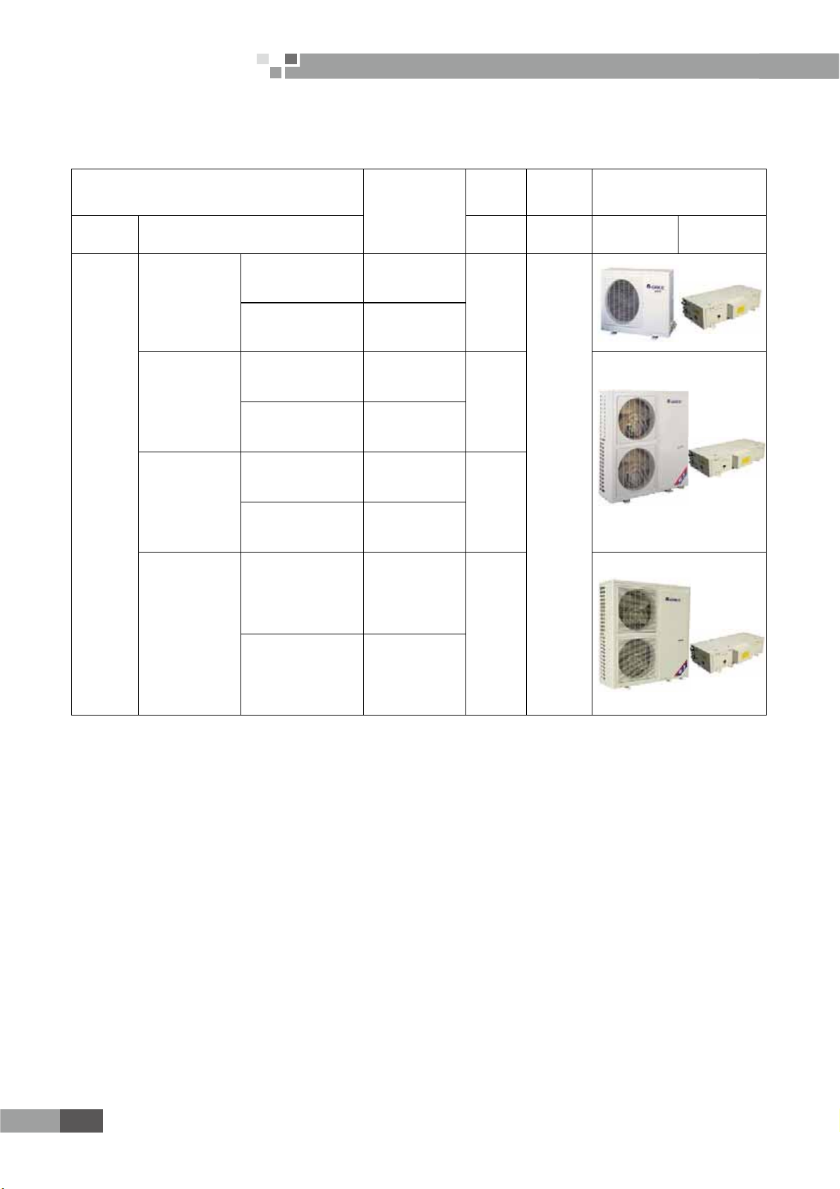
1 MODELS LIST ..........................................................................................................................2
1.1 Split Type...........................................................................................................................................................2
1.2 Integral Type.....................................................................................................................................................3
2 NOMENCLATURE....................................................................................................................3
1.1 Split Type...........................................................................................................................................................3
1.2 Integral Type.....................................................................................................................................................4
3 FUNCTION.................................................................................................................................4
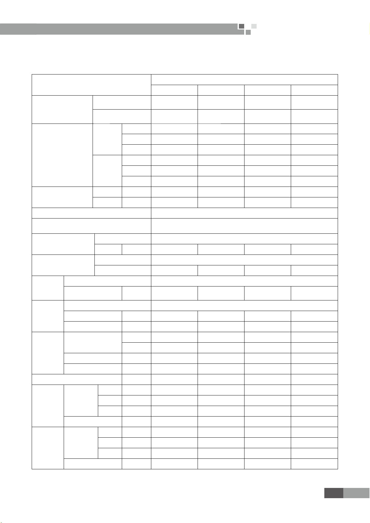
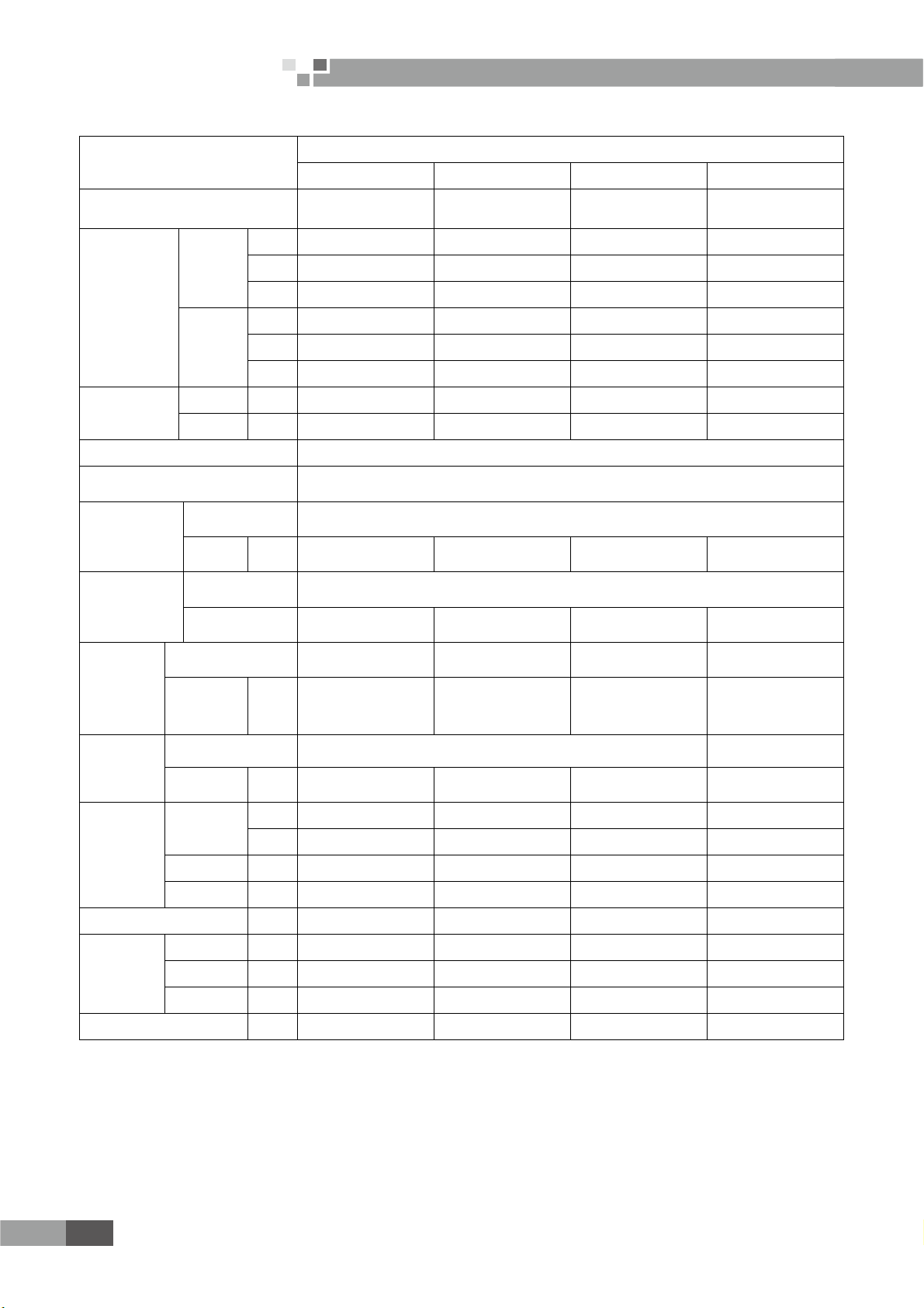
4 PRODUCT DATA.......................................................................................................................5
4.1 Product Data at Rated Condition...................................................................................................................5
4.2 Operation Range...............................................................................................................................................7
4.3 Electrical Data..................................................................................................................................................7
5 PIPING DIAGRAM...................................................................................................................7
UNITS CONTROL.......................................................................................................9
1 OPERATION FLOWCHART...................................................................................................9
1.1 Cooling Operation............................................................................................................................................9
1.2 Heating Operation..........................................................................................................................................10
2 MAIN LOGIC...........................................................................................................................11
2.1 Cooling Mode..................................................................................................................................................11
2.2 Heating Mode..................................................................................................................................................11
2.3 Defrosting Mode.............................................................................................................................................12
3 WIRED CONTROLLER ........................................................................................................12
3.1 Dimension........................................................................................................................................................12
3.2 Function...........................................................................................................................................................13
3.3 Installation......................................................................................................................................................15
4 CONTROL WIRING DESIGN...............................................................................................16
UNITS INSTALLATION ..........................................................................................18
1 UNITS INSTALLATION.........................................................................................................18
1.1 Installation Positions......................................................................................................................................18
1.2 Matters need Attention..................................................................................................................................18
1.3 DIMENSION DATA.......................................................................................................................................18
1.4 INSTALLATION CLEARANCE DATA .....................................................................................................21
2 WATER PIPING WORK..........................................................................................................23
2.1 Installation Procedure....................................................................................................................................23

2.2 Matters of Attention.......................................................................................................................................23
2.3 Antifreeze.........................................................................................................................................................23
3 ELECTRIC WIRING WORK.................................................................................................23
3.1 Wiring Principle.............................................................................................................................................23
3.2 SPECIFICATION OF POWER CORD & AIR SWITCH.........................................................................23
3.3 WIRING DIAGRAM.....................................................................................................................................23
UNITS MAINTENANCE ..........................................................................................28
1 ERROR CODE LIST................................................................................................................28
2 FLOW CHART OF TROUBLESHOOTING........................................................................29
3 DISASSEMBLY AND ASSEMBLY PROCEDURE OF MAIN PARTS..............................31
3.1 Split Type..........................................................................................................................................................31
3.2 Integral Type....................................................................................................................................................39
4 EXPLODED VIEWS AND PART LIST..................................................................................43
4.1 Exploded Views and Parts List- Split Type...................................................................................................43
4.2 Exploded Views and Parts List- Integral Type............................................................................................52

1
Mini Chiller Service Manual
PRODUCT
QSPEVDU

2
Mini Chiller Service Manual
QSPEVDU
PRODUCT
1 MODELS LIST
1.1 Split Type
Model
Product Code
Nominal
Capacity
Power
Supply Appearance
Refrigerant Model Name kW (V,Ph,Hz) Outdoor Unit Indoor Unit
R410A
HLR8WZNa-M
HLR8WZNa-M˄I˅EM113N0030
8.0
380 415V 3Ph 50Hz
HLR8WZNa-M˄O˅EM113W0030
EM113W0031
HLR10WZNa-M
HLR10WZNa-M˄I˅EM113N0020
10.0
HLR10WZNa-M
˄O˅EM113W0020
EM113W0021
HLR12.5WZNa-M
HLR12.5WZNa-M
˄I˅EM113N0040
12.5
HLR12.5WZNa-M
˄O˅EM113W0040
HLR15WZNa-M
HLR15WZNa-M˄I˅EM113N0010
15.0
HLR15WZNa-M
˄O˅EM113W0010
EM113W0011
Note:1Ton =12000Btu/h = 3.517kW

3
Mini Chiller Service Manual
QSPEVDU
1.2 Integral Type
Model
Product Code
Nominal
Capacity
Power
Supply
Appearance
Refrigerant Model Name kW (V,Ph,Hz)
R410A
HLR22SNa-M EM15000030 22
380 415V 3Ph 50Hz
HLR25SNa-M EM116N0270 25
HLR35SNa-M EM116N0260
EM116N0261 35
HLR45SNa-M EM15000040
EM15000041 45
Note:1Ton =12000Btu/h = 3.517kW
2 NOMENCLATURE
1.1 Split Type
HL R 15 W Z Na - M
123456 7
NO. Description Options
1 Mini chiller -
2 Product type R=Heat pump
3 Nominal Cooling Capacity
8=8kW
10=10 kW
12.5= 12.5kW
15= 15kW
4 Struct type Default=Vertical type
W=Horizontal type
53URGXFWFRQ¿JXUDWLRQ Z=Combination
6 Refrigerant Na=R410A, Default=R22
7 Voltage M=380 415V 3Ph 50Hz

4
Mini Chiller Service Manual
QSPEVDU
1.2 Integral Type
HL R 35 S Na - M
12345 6
NO. Description Options
1 Mini chiller -
2 Product type R=Heat pump
3 Nominal Cooling Capacity
22=22kW
25=25kW
35=35kW
45=45kW
4 Refrigeration Circuits Default=One circuit
S=Twin circuit
5 Refrigerant Na=R410A, Default=R22
6 Voltage M=380 415V 3Ph 50Hz
3 FUNCTION
Indoor Unit Type Function Description
Split Type
Heating/Cooling
Interface kit for up to 16 indoor units
Memory restart
Two circuits optimized design
Low noise design
Safety and reliability thanks to advance
compressor balance control
Integral Type

5
Mini Chiller Service Manual
QSPEVDU
4 PRODUCT DATA
4.1 Product Data at Rated Condition
4.1.1 Split Type
Models
HLR_WZNa-M
8 10 12.5 15
Product Code
Indoor unit EM113N0030 EM113N0020 EM113N0040 EM113N0010
Outdoor unit EM113W0030
EM113W0031
EM113W0020
EM113W0021 EM113W0040 EM113W0010
EM113W0011
Nominal Capacity
Cooling
kW 7.5 10 12.5 14.2
Btu/h 25590 34120 42650 48451
RT 2.1 2.9 3.6 4.0
Heating
kW 9 12 13 16.5
Btu/h 30708 40944 44357 56298
RT 2.6 3.4 3.7 4.7
Power Consumption
Cooling kW 3.5 4.4 5.7 5.7
Heating kW 3.3 4.4 4.8 5.3
Power Supply 380~415V,3Ph,50Hz
Safeties High/Low pressure switch, compressor thermal protection, over current protection, lose of
SKDVHDQWLSKDVHSURWHFWLRQDQWLIUHH]LQJSURWHFWLRQZDWHUÀRZVZLWFK
Refrigerant
Type R410A
Charge kg 3.1 3.55 4.5 5.5
Compressor
Type scroll
NO. 1111
Evaporator
Heat Exchanger Tube-in-Tube
Water In/Out Pipe
Diameter Inch 1" 1" 1" 1"
Condenser
Heat Exchanger $OXPLQXP¿QFRSSHUWXEH
Fan Motor Power Input kW 0.092 0.068 0.092 0.092
Fan quantity 1222
Pump
Water Flow
L/s 0.38 0.48 0.59 0.72
GPM 5.0 6.3 7.79 9.5
Delivery Lift m 18 18 18 18
Power Input kW 0.55 0.55 0.55 0.55
Expansion Vessel Volume L 5555
Indoor
Unit
Unit /
Packing
Dimension
Height mm 288/385 288/385 288/385 288/385
Width mm 1100/1285 1100/1285 1100/1285 1100/1285
Depth mm 450/682 450/682 450/682 450/682
Net/Gross Weights 84/96 84/96 84/96 84/96
Outdoor
Unit
Unit /
Packing
Dimension
Height mm 840/985 1250/1385 1250/1385 1250/1385
Width mm 950/1110 950/1110 950/1110 950/1110
Depth mm 412/450 412/450 412/450 412/450
Net / Gross Weights 90/100 112/123 115/126 123/134

6
Mini Chiller Service Manual
QSPEVDU
4.1.2 Integral Type
Models
HLR_SNa-M
22 25 35 45
Product Code EM15000030 EM116N0270 EM116N0260
EM116N0261
EM15000040
EM15000041
Nominal
Capacity
Cooling
kW 21.5 22.8 31 42
Btu/h 73358 77794 105773 143304
RT 6.1 6.5 8.8 11.9
Heating
kW 25 25 37.5 49
Btu/h 85301 85301 127950 167189
RT 7.1 7.1 10.7 13.9
Power
Consumption
Cooling kW 8.6 8.8 11.9 18.3
Heating kW 8.6 8.9 12.5 17.5
Power Supply 380~415V 3Ph 50Hz
Safeties High/Low pressure switch, compressor thermal protection, over current protection, lose of phase/anti-
SKDVHSURWHFWLRQDQWLIUHH]LQJSURWHFWLRQZDWHUÀRZVZLWFK
Refrigerant
Type R410A
Charge kg 3.6×2 4.8×2 6.5×2 7.3×2
Compressor
Type scroll
NO.2222
Evaporator
Heat Exchanger Tube-in-Tube Tube-in-Tube Shell in tube Shell heat exchanger
Water In/
Out Pipe
Diameter
Inch 1" 1" 1-1/2" 1-1/2"
Condenser
Heat Exchanger $OXPLQXP¿QFRSSHUWXEH Fin sleeve Heat
exchanger
Fan Motor
Power Input kW 0.4 0.4 0.6 0.8
Pump
Water Flow
L/s 1.05 1.2 1.4 2.2
GPM 13.9 15.8 22 29
Delivery Lift m 22 24 25 27
Power Input kW 0.75 0.75 1.5 1.5
Expansion Vessel Volume L 8888
Unit / Packing
Dimension
Height mm 1850/2100 1850/2100 1760/1970 1760/1970
Width mm 1460/1540 1460/1540 1750/1910 1750/1910
Depth mm 530/610 530/610 800/960 800/960
Net/Gross Weights kg 370/380 390/400 680/690 755/765
Notes˖
a. Cooling capacity is based on the following conditions˖leaving chilled water temp.7ć,outdoor air temp.35ć
b. Heating capacity is based on the following conditions˖leaving warmed water temp.45ć, outdoor air temp.7ć
c. :DWHUÀRZUDQJHIRURSHUDWLRQPXVWEHIURPWRRIWKHUDWHGZDWHUÀRZ
d. The maximum allowable pressure for water pipe is 0.9MPa.

7
Mini Chiller Service Manual
QSPEVDU
4.2 Operation Range
Mode Range of Outdoor Temperatureć( )
Cooling 16~48
Heating -15~28
4.3 Electrical Data
4.3.1 Split Type
Model Rated Power
Supply
Compressor
Fan Motor
Pump Total
Outdoor
NO. LRA each
˄A˅
MRC each
˄A˅NO. MRC
˄A˅
MRC
˄A˅
MRC
˄A˅
NRC
˄A˅
HLR8WZNa-M
380~415V
3Ph 50Hz
1 67 9.1 1 1.5 0.7 9.4 7.0
HLR10WZNa-M 1 66 11.6 2 2.0 0.7 13.0 8.5
HLR12.5WZNa-M 1 67 13.7 2 2.0 0.7 14.5 10.5
HLR15WZNa-M 1 67 13.7 2 2.0 0.7 14.5 10.5
4.3.2 Integral Type
Model Rated Power
Supply
Compressor Fan Motor Pump Total
NO. LRA each
˄A˅
MRC each
˄A˅NO. MRC
˄A˅
MRC
˄A˅
MRC
˄A˅
MRC
˄A˅
HLR22SNa-M
380~415V
3Ph 50Hz
2 73 11.6 2 5.0 1.5 19.5 14.5
HLR25SNa-M` 2 66 13.5 2 5.0 1.5 23.5 18.5
HLR35SNa-M 2 101 16.4 2 7.5 3.0 28.5 24.5
HLR45SNa-M 2 118 22.5 2 7.5 3.0 45.0 31.0
Notes:
a. LRA: Locked rotor amps (A).
b. MRC: Maximum running current (A).
c. NRC: Nominal running current (A).
5 PIPING DIAGRAM
Heating circuit
Cooling circuit
Pump
Relief
valve
Flow
switch drum
Expansion
High pressure
tank
Aluminum fin-copper tube
coil
Four-way valve
Shell and tube heat
exchanger
Inlet
Outlet
High-pressure
switch
Compressor
Low-pressure
switch
Liquid-gas separator
F

8
Mini Chiller Service Manual
CONTROL
DPOUSPM

9
Mini Chiller Service Manual
DPOUSPM
UNITS CONTROL
1 OPERATION FLOWCHART
1.1 Cooling Operation
NY
N
Y
Y
N

10
Mini Chiller Service Manual
DPOUSPM
1.2 Heating Operation
NY
N
Y
Y
N

11
Mini Chiller Service Manual
DPOUSPM
2 MAIN LOGIC
2.1 Cooling Mode
When pressing ON button, if the outdoor temperature is above 16 ćZDWHUSXPSZLOOVWDUW¿UVW$IWHUVLIWKH
outlet water temperature meets the cooling running requirements, the fans of outdoor unit will start. Then the compressor
will run in 15s. During the period of cooling, the unit will be turned off if the outlet water temperature meets the stopping
requirements and the running time of compressor is over the shortest running time required. The fans of outdoor unit will
stop in15s.
If the outdoor temperature is below 16ć, the unit will stop, and all loads except the water pump will be turned off.
Turn on
Pump 1
Fan 2
Flow Switch
Compressor 1
30S
15S
Check if flow switch is ok
Turn off
5S
5S
Compressor 2
14>Tout>7
15>Tout>8
3min
Four-way valve 1
Four-way valve 2
10min
15>Tout>12
Fan 1
30S
When it is turned off
5S
3min
15S
15S
When it is turned off
2.2 Heating Mode
When pressing ON button, if the outdoor temperature is below 28ćWKHZDWHUSXPSZLOOVWDUW¿UVW$IWHUVLIWKH
outlet water temperature meets the heating running requirements, the fans of outdoor unit will start. Then the compressor
will run in 15s. During the period of cooling, the unit will be turned off if the outlet water temperature meets the stopping
requirements and the running time of compressor is over the shortest running time required. The fans of outdoor unit will
stop in15s.
If the outdoor temperature is over 28ć, the unit will stop, and all loads except the water pump will be turned off.

12
Mini Chiller Service Manual
DPOUSPM
Pump
Fan 2
Flow Switch
Compressor 1
Turn on Turn off
Compressor 2
Four-way valve 1
Four-way valve 2
Fan 1
30S
Check if flow switch is ok
5S
15S
48<Tout<54
46<Tout<52
3min
15S
15S
When it is turned off
3min
15S
15S
5S
5S
2S
30S
5S
When it is turned off
2.3 Defrosting Mode
The condition of start defrosting mode:
Under heating mode, if the accumulative running time of compressor is over the set interval time of defrosting
˄default 45min˅ˈand the defrosting temperature is lower than the set starting temperature(default -4ć) ,the unit will
start running defrosting mode, and the 4-way valve will shut off and the outdoor fan will stop after 2s.
The condition of quit defrosting mode:
Under defrosting mode, if the continual defrosting time is over the set continual time of defrosting˄default
8min˅ˈand the defrosting temperature is over the set stopping temperature(default 20ć) ,the unit will restart running
heating mode, and the 4-way valve will turn on and the outdoor fan will run.
3 WIRED CONTROLLER
3.1 Dimension
installation dimension
60
outline dimension
85
42.5
85 85
85
85 21.2

13
Mini Chiller Service Manual
DPOUSPM
3.2 Function
3.2.1 Operation View
6
7
8
5
4
3
2
1
NO. Name Function description
1 MODE button It can switch between cooling and heating. This button is available only on heat pump unit.
2 CHECK button
Press it once under normal state to enter check mode. Under check mode, pressing this button when
“17” is displayed can change the value of “17”. Under parameter setting mode, pressing this once
can switch the adjusting objection between parameter and value, and pressing this button for long
(about 5s) can save and quit this parameter setting.
3 Increasing button To increase present set value or change set/check object.
4 Decreasing button To decrease present set value or change set/check object.
5 QUIT button
Under Set and Check mode, press it once to quit this mode. Under parameter set mode, this set
value would not be saved. Press this button for long (about 5s) to set sound, and make sound switch
between always on and always off.
6 ON button To turn on the unit; when under compel operation, press it once to quit compel operation.
7 OFF button To turn off the unit; press it once to quit compel operation when the unit is under compel operation.
8 LCD display Display information of the unit.
Notes˖
a. Turn On, Off Auxiliary Heater: It is only available for heat pump unit. Press CHECK once to enter Check mode.
3UHVVŸDQGźWRFKDQJHFKHFNREMHFWDQGSUHVV&+(&.DJDLQWLOOWKHSUHVHQWFKHFNREMHFWEHFRPHV³´9DOXH³´
switches between 01/03 (auxiliary heater on) and 00/02 (auxiliary heater off). That is 00 Off —>01 On —>00 Off, or 02
Off —>03 On —>02 Off.
b. &KHFN3DUDPHWHU$IWHUHQHUJL]DWLRQIRUVSUHVV48,7WKHQŸWRHQWHUSDUDPHWHUFKHFNLQJPRGH8QGHUWKLV
mode, Auxiliary display area shows the checking object, and Main display area displays the value for the checking object.
3UHVVŸDQGźWRFKDQJHWKHFKHFNLQJREMHFW3UHVV48,7WRTXLWIURPWKHFKHFNPRGH

14
Mini Chiller Service Manual
DPOUSPM
3.2.2 Display View
NO. Name Function description
1 Running mode display : cooling mode, : heating mode, : reserved
2 Temp display It shows temperature value at main display area.
3 Auxiliary display area It contains 2 numbers and a comma, for showing temperature and number of parameter at main display area.
It only displays when under Check mode and Parameter checking mode.
4 Main display area
It contains a minus, 2 numbers and 1 temperature unit, for displaying value of temperature and parameter
(temperature or time value) and error code. When temperature value is displayed, it shows value in algorism
and temperature unit; when time is displayed, it shows algorism value but without temperature unit
GHIDXOWXQLWLVPLQZKHQLWLVFRGHLWGLVSOD\VVSHFL¿FHUURUUHIHUWR0DOIXQFWLRQ(UURU/LVWEXWZLWKRXW
temperature unit. Individual temperature or parameter may exceed 99, then adopt AX for 100 109, bX for
110 119, CX for 120 129, dX for 130 139, EX for 140 149, FX for 150 159, and X stands for
a number between 0 9. Under normal state, it shows temperature for back water.
5 Parameter display It means the value shown at present main display area is parameter. It shows only under Parameter Check
mode.
6 Defrost display It displays when defrosting; otherwise it doesn’t displays.
7 System ID It displays when system or compressor orders, for showing which system is defrosting.
8 Testing display For testing, it displays under compel operation.
9 Error code display It shows the error code displayed on Main Display Area. It displays when there is error at system or
communication.
Caution:
1) When unit is off, it displays only temperature of back water. When unit is on, under normal state, if there is no
error, it displays temperature of back water, if there is error, it displays error code; when there is no operation after 60s of
pressing the button, it quit back to normal state display automatically.
2) Auto antifreeze operation display (only for heat pump unit)
:KHQDXWRDQWLIUHH]HIXQFWLRQLVVWDUWHGDQGUHOHYDQWFRQGLWLRQVDUHVDWLV¿HGXQLWEHJLQVDXWRDQWLIUHH]HRSHUDWLRQ$W

15
Mini Chiller Service Manual
DPOUSPM
this time, LCD main display area displays code d2 (if there is error it displays error code).
3.3 Installation
1) First select an installation position. According to the size of the communication line of the wire controller, leave a
recess or an embedded wire hole to bury the communication line.
2) If the communication line between the wire controller (85×85×20) and the indoor unit is surface-mounted, use 1#
PVC pipe and make matching recess in the wall (refer to Figure 6); If concealed installation is adopted, 1# PVC pipe can
be used (Refer to Figure 7).
3) No matter if surface mounting or concealed mounting is selected, it is required to drill 2 holes (in the same level)
which distance shall be the same as the distance (60mm) of installation holes in the bottom plate of the wire controller.
Then insert a wood plug into each hole. Fix the bottom plate of the wire controller to the wall by using the two holes. Plug
the communication line onto the control panel. Lastly install the panel of the wire controller.
Caution:
During the installation of the bottom plate of the wire controller, pay attention to the direction of the bottom plate.
The plate’s side with two notches must be at the lower position, and otherwise the panel of the wire controller cannot be
correctly installed.
PVC pipe
Fig6˖Surface Mounting of Cable
Fig7˖Concealed mounting of Cable
1 32 4
Fig 8 Schematic Diagram of Installation
No. Name
1 Wall Surface
2 Bottom Plate of Wire Controller
3 Screw M4X10
4 Panel of Wire Controller
Caution:
1) The communication distance between the main board and the wire controller can be as far as 20m (The standard
distance is 8m).
2) The wire controller shall not be installed in a place where there is water drop or large amount of water vapor.

16
Mini Chiller Service Manual
DPOUSPM
4 CONTROL WIRING DESIGN
twisted-pair
twisted-pair
X17J1
CN2
CN1
Outdoor Unit Controller
Manual Unit Controller
Indoor Unit Controller
The controllers of the split type unit include manual controller, indoor unit controller and outdoor unit controller.
The indoor unit controller communications with manual controller and outdoor unit controller in RS485. The indoor unit
controller connects manual controller with 4-line twisted-pair. Similarly, the indoor unit controller connects outdoor unit
controller with 4-line twisted-pair.
Indoor Unit Controller
Manual Unit Controller
Outdoor Unit Controller
J1
X17
twisted-pair
The controllers of the Integral type unit include manual controller and outdoor unit controller. The manual controller
communications with outdoor unit controller in RS485. The manual controller connects outdoor unit controller with 4-line
twisted-pair.

17
Mini Chiller Service Manual
INSTALLATION
This manual suits for next models
7
Table of contents
Other Gree Chiller manuals

Gree
Gree T1/R410A/50Hz User manual

Gree
Gree LSQWF65M/N-M User manual

Gree
Gree EVO Series User manual

Gree
Gree C Series User manual

Gree
Gree LSQWRF35VM/NaA-M User manual

Gree
Gree D Series User manual

Gree
Gree GWH07AGA-K6DNA1C User manual

Gree
Gree GK-C03TC1AD User manual

Gree
Gree T1/R22 User manual

Gree
Gree FB01 User manual
Popular Chiller manuals by other brands

Beretta
Beretta HYDRONIC UNIT B HE 5 Installer manual

KKT
KKT KPC 108-L-U/S Operating instruction

Daikin
Daikin EWWD120J-SS Installation, operation and maintenance manual

Carrier
Carrier 30PA 90 Installation, operation and maintenance instructions

Bracton
Bracton Subzero SZSC1800 product manual

McQuay
McQuay MAC060D4 Installation, operation & maintenance manual