Limit d Warranty
DIP Switch S ttings
Troubl shooting
All products manufactured by Cooper Controls and identified with the Greengate brand are warranted to be free from defects in
material and workmanship and shall conform to and perform in accordance with Seller’s written specifications for a period of: Five
(5) years from date of shipment for all occupancy sensors and Three (3) years from date of factory invoice for our hardware and
software on Lighting Control Panels. We warranty all our standard relays for a period of 10 years from date of factory invoice. We
guarantee the performance of our system to specifications or your money back. This warranty will be limited to the repair or
replacement, at Seller’s discretion, of any such goods found to be defective, upon their authorized return to Seller. This limited
warranty does not apply if the goods have been damaged by accident, abuse, misuse, modification or misapplication, by damage
during shipment or by improper service. There are no warranties, which extend beyond the hereinabove-limited warranty,
INCLUDING, BUT NOT LI ITED TO, THE I PLIED WARRANTY OF ERCHANTABILITY AND THE I PLIED WARRANTY OF FITNESS.
No employee, agent, dealer, or other person is authorized to give any warranties on behalf of the Seller or to assume for the Seller
any other liability in connection with any of its goods except in writing and signed by the Seller. The Seller makes no representa-
tion that the goods comply with any present or future federal, state or local regulation or ordinance. Compliance is the Buyer’s
responsibility. The use of the Seller’s goods should be in accordance with the provision of the National Electrical Code, UL and/or
other industry or military standards that are pertinent to the particular end use. Installation or use not in accordance with these
codes and standards could be hazardous.
Cooper Controls
203 Cooper Circle, Peachtree City, GA 30269
800-553-3879
www.coopercontrol.com
P/N 910-0539
REV B
Ch ckout and Adjustm nt
LOAD 1
120 to 277 VAC BLACK BLUE
NEUTRAL
GROUND
GREEN
WHITE LOAD 2
A/B SWITCHING USING TOGGLE
SWITCH TO TURN OFF SECOND LOAD
LOAD 1
BLACK BLUE
NEUTRAL
THREE-WAY WIRING DIAGRAM:
LIGHTS WILL TURN OFF, WHEN UNIT THAT WAS TURNED ON LAST AND/OR DETECTED MOTION LAST TIMES-OUT.
GROUND
GREEN
WHITE
120 to 277 VAC
BLACK
BLUE
GROUND
GREEN
WHITE
TRAVELER
WIRES
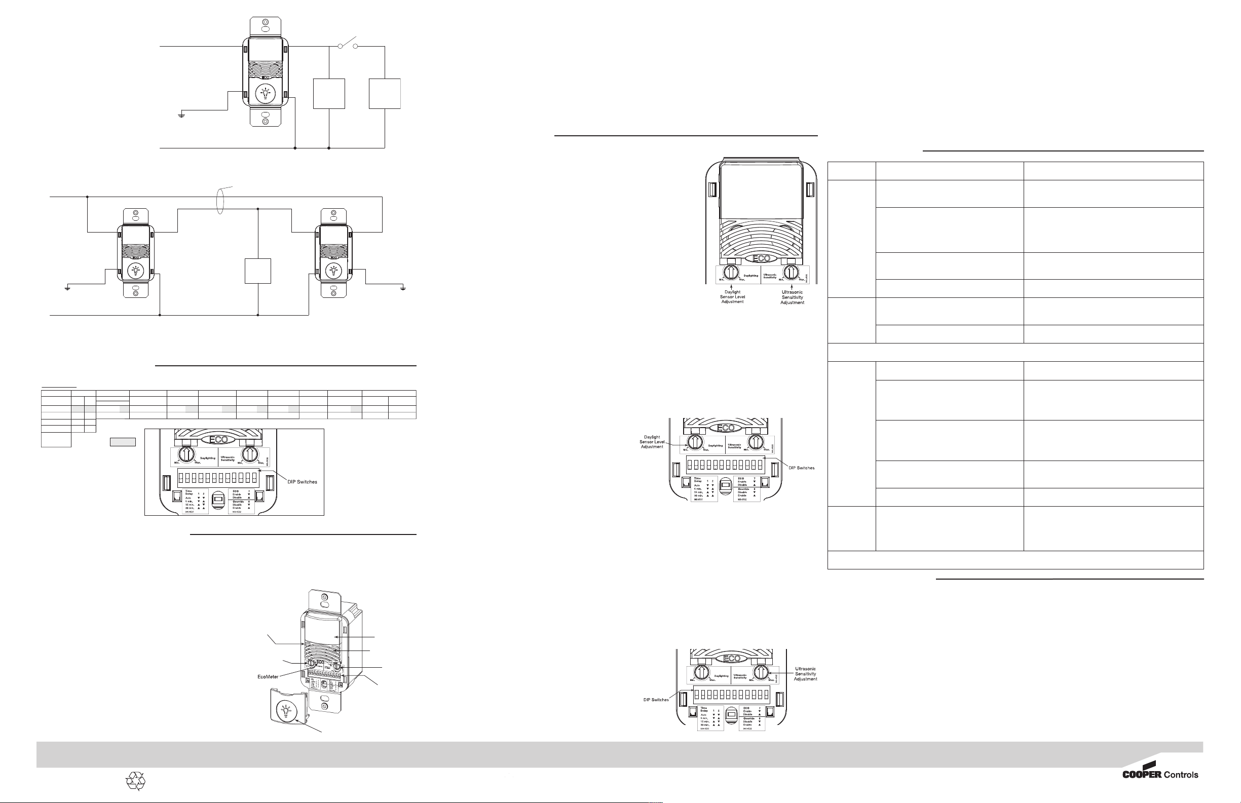
Wiring Diagram 3: 120 to 277 AC single level single circuit three-way wiring diagram
Wiring Diagram 2:
120 to 277 AC single level
switch dual level wiring using a
toggle switch wiring diagram
as the self-adjusting feature is enabled, the switch will respond to each pair of False-offs with no normal off in between
by alternately making slight adjustments to either Time Delay (by 2 minute increments) or sensitivity, so there should be
no need for manual adjustment. If manual adjustment is desired, refer to Time Delay settings in DIP Switch legend.
Reset sensor Time Delay to factory settings by moving DIP Switches 1 and 2 down. (If DIP Switches 1 and 2 are
already down, toggle DIP Switch 1 out of its current position, wait 3 seconds, and then back to its original position)
Ov rrid
The override setting allows the sensor to operate as a service switch in the unlikely event of failure.
1. ove DIP Switch 8 up.
2. The Pushbutton can be used to manually turn lights ON or OFF.
9 10 11 12
Not Used
5 Minutes
Auto*
*Self-Adjusts to
10 min. user mode
Time Delay
DIP Switch
Activation PIR Sensitivity Override
Relay 1
EcoMeter
Walk-Through Mode
Default =
30 Minutes
15 Minutes
12
DIP Switch Legend
6
q
p
Disable
Enable
3
qq
q
q
qpp
pp
p
Auto
Manual
5
q
p
Full
50%
8
q
pp
q
7
Enable
Disable
4
Disable
Enable
Not Used Maintain Lights On Not Used
12119 10
q
p
Either
Both
Adjustments should be made with the HVAC system on so that the installer will be able to detect the effect of air-
flow on the operation of the ONW-D-1001- V-N. Use only insulated tools to make adjustments.
Immediately after applying power to the lighting circuit, wait approximately two minutes for the switch to power up
and stabilize.
S lf-Adjust Mod
Sensor is shipped in self-adjust mode. This applies to
Time Delay, US and PIR sensitivity. In preparation for the
Installer Test, the Time Delay is set to 15 seconds, after the
sensor is installed, powered ON and has stabilized, the unit
will Time-out 15 seconds after the last motion detected.
Coverage and sensitivity can be confirmed by watching the
Green (US) and Red (PIR) indicator LEDs on the front of the
sensor, while moving around the room.
1. Walk around the room and monitor LEDs.
2. Stand in different parts of the room and wave your
hands. LEDs should only turn ON for one second with
each motion. (If LEDs do not turn ON, go to Installer Adjustments – Sensitivity Adjustment Section)
3. Stand still three to four feet away from sensor for five seconds. LEDs should not turn ON. (If any LED turns ON,
note LED and go to Installer Adjustments – Sensitivity Adjustments section)
4. Walk outside the room and wait 15 seconds for the lights to turn OFF. (If lights do not turn OFF go to Installer
Adjustments Section)
5. Re-enter the room to activate sensor. (If lights do not turn ON go to Troubleshooting Section)
6. At this point you can exit the room and let the sensor Time-out. When the sensor times-out and is inactive for five
minutes, the unit will go to a 10 minute Time Delay user mode setting.
Note: To place into Test ode, toggle DIP Switch 12 out of its current position, wait 3 seconds, and then back in to its original position.
Install r Adjustm nts
S nsitivity Adjustm nts
Ultrasonic Sensitivity (Green LED) – Using a small flathead screw driver turn the
green potentiometer so that the arrow points UP.
1. Stand in different areas of the room and wave your hands.
2. If the Green LED does not turn ON, increase the US sensitivity by turning the
green potentiometer clockwise in small increments. Repeat Step 1.
3. Stand still three to four feet away from sensor for five seconds. LED should
not turn ON.
4. If Green LED turns ON without motion or is constantly ON decrease the US
sensitivity by turning green potentiometer counter-clockwise in small
decrements. Repeat Step 3.
Note: Do Not adjust sensitivity higher than necessary.
PIR S nsitivity
1. Stand in different areas of the room and wave your hands.
2. If the Red LED does not turn ON, check for any obstructions.
3. Stand still three to four feet away from sensor for five seconds. LED should not turn ON.
4. If Red LED turns ON without motion or is constantly on adjust PIR sensitivity to 50 % by moving DIP Switch 5 up.
ON/OFF Disabl d F atur
1. ON/OFF Button Disable Option – When selected this option disables the ON/OFF button and sensor becomes automatic
only control regardless of the setting for automatic or manual activation. This feature will not allow someone to turn
light(s) OFF via the Pushbutton while people are in common areas such as restroom, break room, and copy room areas.
Fi ld-of-vi w outsid th spac
1. Adjust PIR sensitivity to 50 % by moving DIP Switch 5 up.
2. Use non-reflective tape strips to cover the portions of the
sensor lens that view outside the space.
3. Adjust Ultrasonic Sensitivity.
Daylight Adjustm nts
The daylighting feature prevents the lights from turning ON
when the room is adequately illuminated by natural light. If there
is enough light in the room regardless of occupancy, the sensor will hold the lights OFF. If there is not enough light in the
room, the sensor will allow the lights to turn ON when occupied. The sensor will not allow the daylighting feature to turn the
load OFF until the space is vacant or the light level rises above the setpoint and the Time Delay expires. While in anual
Activation ode, if someone attempts to turn the load ON and there is sufficient daylight available the Daylighting feature will
hold the lights OFF.
• Set the light level when the ambient light is at the level where no artificial light is needed. If this feature is not needed,
leave the light level at maximum (fully CW).
1. With the load(s) ON, put the sensor into Test ode. To place into Test ode, toggle DIP Switch 12 out of its current
position, wait 3 seconds and then back in to its original position.
2. Set the Light level to minimum (fully CCW).
3. Let the sensor Time-out so lights are OFF. Enter the space and lights should remain OFF.
4. ake sure not to block the sensor from the daylight source and
adjust the light level potentiometer CW in small incre-
ments. (Pause 5 seconds between each adjustment)
5. Once the lights are ON, the load connected to the sensor will
not turn ON if light levels are above the current illumination.
Tim D lay Adjustm nts
People who remain very still for long periods of time may need a
longer Time Delay than the default setting of 10 minutes. As long
ON/OFF Button
PIR Lens
DIP Switches
Ultrasonic Detection
Daylight
Sensor Level
Adjustment Ultrasonic
Sensitivity
Adjustment
Red (PIR) & Green (US)
Detection LEDs
Issu Possibl Caus s Sugg stions
Lights
Will Not
Turn ON
automatically
Sensor is in anual ON mode Press Pushbutton. If Auto ode
is desired change Activation ode to Auto.
Sensor was turned OFF manually. If the Sensor
was turned OFF manually before the Time Delay
expired, lights will remain OFF for the remainder
of the Time Delay.
Check Eco eter LED. If LED is ON this is
an indication that the lights were turned OFF manually.
Press the Pushbutton to turn the lights back ON.
Daylight Feature Enabled If all lights are required to turn ON
adjust daylight potentiometer.
Power interruption Check incoming voltage and/or wiring.
Lights
Will Not
Turn ON
manually
Daylight Feature Enabled If all lights are required to turn ON
adjust daylight potentiometer.
Power interruption Check incoming voltage and/or wiring.
If lights will still not turn ON, s t s nsor to ov rrid mod and call T chnical S rvic s at 1-800-553-3879
Lights
Will Not
Turn OFF
automatically
Override ake sure sensor is not in Override ode (DIP Switch 8 up).
Self-Adjust
If sensor is in Self-Adjust ode, it may be possible for the
unit to have increased the Time Delay to a 30 minute delay.
If the lights do not turn OFF after 30 minutes follow next step.
30 inute Delay
aximum Time Delay is 30 inutes. Check DIP Switches
to verify DIP Switch settings. If lights do not turn OFF at the
set Time Delay, check next step.
Ultrasonic Sensitivity set High Lower sensitivity by turning green
potentiometer CCW in small decrements.
PIR activated by heat source other than occupant ove DIP Switch 5 up.
Lights
Will Not
Turn OFF
manually
Call Technical Services
If lights will still not turn OFF, call T chnical S rvic s at 1-800-553-3879
Printed in Malaysia
CAUTION: If a room is wired for two circuits using two separate hot leads, it is very important to connect only
one circuit per relay. Both circuits must be fed from the same phase.


