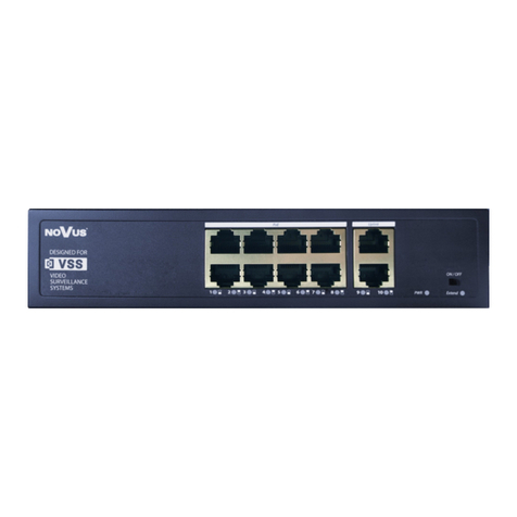
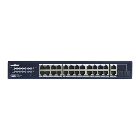
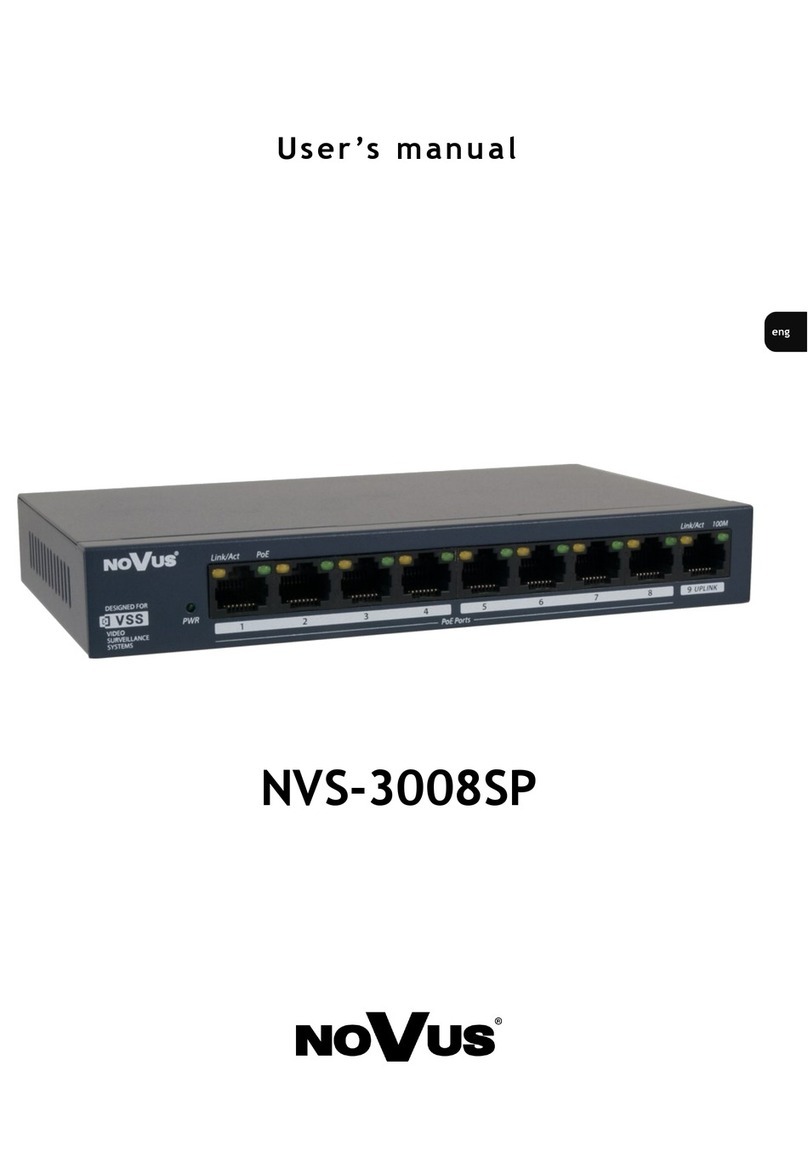
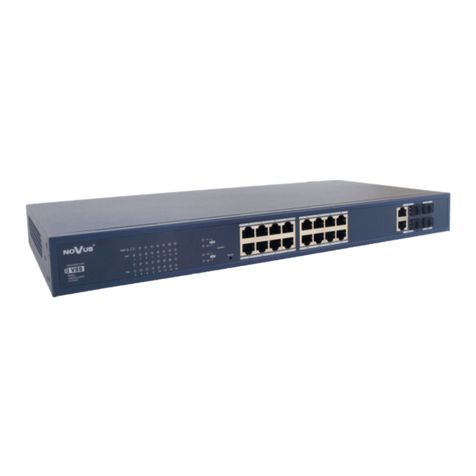
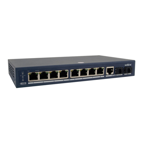
Novus NV-116S/P+ User manual

U s e r ’s ma n u a l
NV-116S/P+
NV-124S/P+

NV-116S/P+ , NV-124S/P+ ,User’s manual ver. 1.0
All rights reserved © AAT Holding S.A.
2
EMC (2004/108/EC) and LVD (2006/95/EC ) Directives
CE Marking
Our products are manufactured to comply with the requirements of the following directives and national
regulations implementing the directives:
Electromagnetic compatibility EMC 2004/108/EC.
Low voltage LVD 2006/95/EC with further amendment. The Directive applies to electrical
equipment designed for use with a voltage rating of between 50VAC and 1000VAC as well as
75VDC and 1500VDC.
WEEE Directive 2002/96/EC
Information on Disposal for Users of Waste Electrical and Electronic Equipment
This appliance is marked according to the European 1000VAC Directive on Waste Electrical and Electronic
Equipment (2002/96/EC) and further amendments. By ensuring this product is disposed of correctly, you
will help to prevent potential negative consequences for the environment and human health, which could
otherwise be caused by inappropriate waste handling of this product.
The symbol on the product, or the documents accompanying the product, indicates that this appliance may
not be treated as household waste. It shall be handed over to the applicable collection point for used up electrical
and electronic equipment for recycling purpose. For more information about recycling of this product, please
contact your local authorities, your household waste disposal service or the shop where you purchased the
product.
RoHS Directive 2002/95/EC
Out of concern for human health protection and friendly environment, we assure that our products
falling under RoHS Directive regulations, regarding the restriction of the use of hazardous substances
in electrical and electronic equipment, have been designed and manufactured in compliance with the
above mentioned regulations. Simultaneously, we claim that our products have been tested and do not
contain hazardous substances whose exceeding limits could have negative impact on human health or natural
environment.
Information
The device, as a part of professional CCTV system used for surveillance and control, is not designed for self
installation in households by individuals without technical knowledge.
The manufacturer is not responsible for defects and damages that result from improper or inconsistent with
user’s manual installation of the device in the system.
INFORMATION
NV-116S/P+ , NV-124S/P+ ,User’s manual ver. 1.0
All rights reserved © AAT Holding S.A.
3
WARNING!
THE KNOWLEDGE OF THIS MANUAL IS AN INDESPENSIBLE CONDITION OF A
PROPER DEVICE OPERATION. YOU ARE KINDLY REQUSTED TO FAMILIRIZE
YOURSELF WITH THE MANUAL PRIOR TO INSTALLATION AND FURTHER
DEVICE OPERATION.
WARNING!
USER IS NOT ALLOWED TO DISASSEMBLE THE CASING AS THERE ARE NO
USER-SERVICEABLE PARTS INSIDE THIS UNIT. ONLY AUTHORIZED SERVICE
PERSONNEL MAY OPEN THE UNIT
INSTALLATION AND SERVICING SHOULD ONLY BE DONE BY QUALIFIED SERVICE
PERSONNEL AND SHOULD CONFORM TO ALL LOCAL REGULATIONS
WARNING!
PRIOR TO UNDERTAKING ANY ACTION THAT IS NOT DESCRIBED FOR THE GIVEN
PRODUCT IN USER’S MANUAL AND OTHER DOCUMENTS DELIVERED WITH THE
PRODUCT, OR IF IT DOES NOT ARISE FROM THE USUAL APPLICATION OF THE
PRODUCT, MANUFACTURER MUST BE CONTACTED UNDER THE RIGOR OF
EXCLUDING THE MANUFACTURER’S RESPONSIBILITY FOR THE RESULTS OF SUCH AN
ACTION.
IMPORTANT SAFEGUARDS AND WARNINGS
1. Prior to undertaking any action please consult the following manual and read all the safety and
operating instructions before starting the device.
2. Please keep this manual for the lifespan of the device in case referring to the contents of this manual
is necessary;
3. All the safety precautions referred to in this manual should be strictly followed, as they have a
direct influence on user’s safety and durability and reliability of the device;
4. All actions conducted by the servicemen and users must be accomplished in accordance with the
user’s manual;
5. The device should be disconnected from power sources during maintenance procedures;
6. Usage of additional devices and components neither provided nor recommended by the producer
is forbidden;
7. Mounting the device in places where proper ventilation cannot be provided (e. g. closed lockers
etc.) is not recommended since it may lead to heat build-up and damaging the device itself
as a consequence;
8. Mounting the device on unstable surface or using not recommended mounts is forbidden.
Improperly mounted switch may cause a fatal accident or may be seriously damaged itself. Switch
must be mounted by qualified personnel with proper authorization, in accordance with this user’s
manual;
IMPORTANT SAFEGUARDS AND WARNINGS

NV-116S/P+ , NV-124S/P+ ,User’s manual ver. 1.0
All rights reserved © AAT Holding S.A.
4
IMPORTANT SAFEGUARDS AND WARNINGS
9. Device should be supplied only from a power sources whose parameters are in accordance with
those specified by the producer in the device’s technical datasheet. Therefore, it is forbidden to
supply the switch from a power sources with unknown parameters, unstable or not meeting
producer’s requirements;
10. Signal and power cables should be placed in a way excluding the possibility of damaging them by
accident. Special attention must be paid to cables getting from the switch and connecting the
power supply;
11. Electric installation supplying the device should be designed to meet the specifications given
by the producer in such a way that overloading is impossible;
12. User cannot repair or upgrade the equipment himself. All maintenance actions and repairs should
be conducted only by qualified service personnel;
13. Unplug the switch from the power source immediately and contact the proper maintenance
department when the following occurs:
Damages to the power cord or to the plug itself;
Liquids getting inside the device or exposure to strong mechanical shock;
Device behaves in a way not described in the manual and all adjustments approved by the
manufacturer and possible to apply by user himself, seem not to have any effect;
Switch is damaged;
Atypical behaviour of the switch components may be seen (heard).
14. In necessity of repairs attention to using only original replacement parts (with their parameters
in accordance with those specified by the producer) should be paid. Non-licensed service and
non-genuine replacement parts may cause fire or electrocution;
15. After maintenance activities tests should be run to ensure proper operation of all the functional
components of the device.
Due to the product being constantly enhanced and optimized, certain parameters and functions described
in the manual in question may change without further notice.
We strongly suggest visiting the www.novuscctv.com website in order to access the newest manual

NV-116S/P+ , NV-124S/P+ ,User’s manual ver. 1.0
All rights reserved © AAT Holding S.A.
5
1. PACKAGE CONTENTS
16 port PoE Management Switch,
RACK mount
Power cable,
User’s manual.
1.1 MAIN CHARACTERISTICS
16 10/100 Mbps PoE ethernet ports support IEEE 802.2af/at standards
PoE network port with IEEE802.3 af/at standards can provide 30W power supply, e.g. for camera
with infrared or heater.
Provide 2 UPLINK ports: 2 x 1000Mbps optical fiber port SFP and 2 x 1000Mbps ethernet port.
UPLINK ethernet port can be connected conveniently to NVR and other high bandwidth device
with distance up to 150 m.
UPLINK optical port SFP is designed for SFP optical fiber modules, solving problem of long
distance transmission.
Fast and easy installation.
FOREWORD INFORMATION
Novus Camera
NVR Switch
Uplink Ethernet 1Gbps

NV-116S/P+ , NV-124S/P+ ,User’s manual ver. 1.0
All rights reserved © AAT Holding S.A.
6
2. PACKAGE CONTENTS
24 port PoE Management Switch,
RACK mount
Power cable,
User’s manual.
2.1. MAIN CHARACTERISTICS
24 10/100 Mbps PoE ethernet ports support IEEE 802.2af/at standards
PoE network port with IEEE802.3 af/at standards can provide 30W power supply, e.g. for camera
with infrared or heater.
Provide 2 UPLINK ports: 2 x 1000Mbps optical fiber port SFP and 2 x 1000Mbps ethernet port.
UPLINK ethernet port can be connected conveniently to NVR and other high bandwidth device
with distance up to 150 m.
UPLINK optical port SFP is designed for SFP optical fiber modules, solving problem of long
distance transmission.
Fast and easy installation.
FOREWORD INFORMATION
Cameras
NVR Switch
Uplink Ethernet 1Gb/s
Uplink fiber1Gb/s

NV-116S/P+ , NV-124S/P+ ,User’s manual ver. 1.0
All rights reserved © AAT Holding S.A.
7
3. SPECIFICATION NV-116S/P+.
FEATURES AND SPECIFICATION
NETWORK
Network Port
Ports 1-16: 10/100Mb/s PoE
Port UPLINK: 10/100/1000 Mb/s
SFP: SFP Module
Transmission Distance
Ports 1-16: recommended 120m, max 150m
Port UPLINK Ethernet : max 150m
PoE+ 1-16: 20m
PoE 1-16: max 150m
PoE Protocol IEEE802.3 af, IEEE802.3 at
Network Standard IEEE802.3 10BASE-T, IEEE802.3u 100BASE-TX, IEEE802.3ab
1000BASE-T, IEEE802.3z 1000BASE-SX\LX
FUNCTIONS
Key Button 1 switch reset button
Surge Protection yes
INSTALLATION PARAMETERS
Dimensions (mm) 315(W) x 44(H) x 442(D)
Weight 3,54kg
Power Supply 230V
Power Consumption <320W
Power Eficiency 250W for all ports, 30 W for a single port
Operating Temperature 0˚C~+55˚C

NV-116S/P+ , NV-124S/P+ ,User’s manual ver. 1.0
All rights reserved © AAT Holding S.A.
8
3.1. SPECIFICATION NV-124S/P+.
FEATURES AND SPECIFICATION
NETWORK
Network Port
Ports 1-24: 10/100Mb/s PoE
Port UPLINK: 10/100/1000 Mb/s
SFP: SFP Module
Transmission Distance
Ports 1-24: recommended 120m, max 150m
Port UPLINK Ethernet : max 150m
PoE+ 1-24: 20m
PoE 1-24: max 150m
PoE Protocol IEEE802.3 af, IEEE802.3 at
Network Standard IEEE802.3 10BASE-T, IEEE802.3u 100BASE-TX, IEEE802.3ab
1000BASE-T, IEEE802.3z 1000BASE-SX\LX
FUNCTIONS
Key Button 1 switch reset button
Surge protection yes
INSTALLATION PARAMETERS
Dimensions (mm) 315(W) x 44(H) x 442(D)
Weight 3,73kg
Power Supply 230V
Power Consumption <420W
Power Eficiency 370W for all ports, 30 W for a single port
Operating Temperature 0˚C~+55˚C

NV-116S/P+ , NV-124S/P+ ,User’s manual ver. 1.0
All rights reserved © AAT Holding S.A.
9
POSITION AND FUNCTIONS OF SWITCH COMPONENTS
4. POSITION AND FUNCTIONS OF NV-116S/P+ SWICH COMPONENTS
A. Ethernet 10/100 1~16 Ports
B. UPLINK Ethernet 10/100/1000 Port
C. UPLINK SFP 10/100/1000 Port
D. Console Port
E. Reset button
F. Ethernet PoE ports LED indicators
G. UPLINK ports LED indicators
H. Power indicator
I. Power supply 100~240V
Front
AB
C
D
E
F
G
H
I
Back

NV-116S/P+ , NV-124S/P+ ,User’s manual ver. 1.0
All rights reserved © AAT Holding S.A.
10
POSITION AND FUNCTIONS OF SWITCH COMPONENTS
4.1. POSITION AND FUNCTIONS OF NV-124S/P+ SWICH COMPONENTS
A. Ethernet 10/100 1~24 Ports
B. UPLINK Ethernet 10/100/1000 Port
C. UPLINK SFP 10/100/1000 Port
D. Console Port
E. Reset button
F. Ethernet PoE ports LED indicators
G. UPLINK ports LED indicators
H. Power indicator
I. Power supply 100~240V
AB
C
D
E
F
G
H
I
Front
Back

NV-116S/P+ , NV-124S/P+ ,User’s manual ver. 1.0
All rights reserved © AAT Holding S.A.
11
SWITCH MANAGEMENT
5. SWITCH MANAGEMENT
User can manage switch via web browser. Device IP address is 192.168.1.200, login and password is
admin/admin. It is required to set computer IP address in the same IP address group address as switch,
due to lack of DHCP server function.
5.1. In the "SYSTEM STATUS" user can change time zone, NTP server or edit switch information.
Time zone
Server NTP
Information data
Hardware information

NV-116S/P+ , NV-124S/P+ ,User’s manual ver. 1.0
All rights reserved © AAT Holding S.A.
12
SWITCH MANAGEMENT
5.2. "PORT SETINGSS" is a tab where user can set connection speed and disable or enable the port.
In "Speed limit" tab user can limit the bandwidth for individual ports or for the group of ports.
5.3. "PoE" tab is a set of helpful features for PoE ports configuration and budget management. We
can set power limits for single ports or for group of ports. Priority settings allow to choose camera to
switch off in case of excessive power demand.

NV-116S/P+ , NV-124S/P+ ,User’s manual ver. 1.0
All rights reserved © AAT Holding S.A.
13
SWITCH MANAGEMENT
5.4. VLAN is helpful in cases where there are too many devices working in network.
VLAN functions allow to separate workstation computers from cameras or servers.
5.5. QoS tab allows to set ports speed priorities.
WARNING !! By default, all switch ports are in VLAN 1, to make
changes in the switch user must be connected to the port "VLAN 1"

NV-116S/P+ , NV-124S/P+ ,User’s manual ver. 1.0
All rights reserved © AAT Holding S.A.
14
5.6 TRUNK tab allows to connect switches using multiple ports, without loop error risk. User gains
multiple speed ports. E.g. if user uses three ports, he gains 300Mbps. Scheme below presents the
implementation.
SWITCH MANAGEMENT
WARNING !! In this implementation TRUNK does not guarantee
redundancy .

NV-116S/P+ , NV-124S/P+ ,User’s manual ver. 1.0
All rights reserved © AAT Holding S.A.
15
SWITCH MANAGEMENT
5.7. "NETWORK MANAGEMENT" tab allows to manage SNMP events. The switch supports three
versions, V1 / V2 / V3.
5.8. "NETWORK STATISTICS" tab allows to monitor "FLOW STATISTICS" tab and MAC table.
5.8.1 FLOW STATISTICS tab
allows to check the status of
transmitted packets.
5.8.2. MAC
table allows to check
the MAC address
connected to the
switch.

NV-116S/P+ , NV-124S/P+ ,User’s manual ver. 1.0
All rights reserved © AAT Holding S.A.
16
SWITCH MANAGEMENT
5.9. "SYSTEM MANAGEMENT" tab allows to change switch IP address settings, user accounts,
update software or to view logs.
5.9.1. IP address settings
5.9.2.User settings
5.9.3.Logs
5.9.4.The File Manager

NV-116S/P+ , NV-124S/P+ ,User’s manual ver. 1.0
All rights reserved © AAT Holding S.A.
17
NOTES

NV-116S/P+ , NV-124S/P+ ,User’s manual ver. 1.0
All rights reserved © AAT Holding S.A.
18
AAT Holding sp. z o.o., ul. Puławska 431, 02-801 Warszawa, Polska
tel.: 22 546 07 00, faks: 22 546 07 59
www.novuscctv.com
2015-07-23 wer. 1.0 TW, MK

NV-116S/P+
NV-124S/P+
I n s t r u kc j a o b s łu gi

NV-116S/P+, NV-124S/P+, instrukcja obsługi wer. 1.0
Wszelkie prawa zastrzeżone © AAT Holding S.A.
2
Dyrektywy EMC (2004/108/EC) i LVD (2006/95/EC)
Oznakowanie CE
Nasze produkty spełniają wymagania zawarte w dyrektywach oraz przepisach krajowych
wprowadzających dyrektywy:
Kompatybilność elektromagnetyczna EMC 2004/108/EC.
Niskonapięciowa LVD 2006/95/EC. Dyrektywa ma zastosowanie do sprzętu elektrycznego
przeznaczonego do użytkowania przy napięciu nominalnym od 50VAC do 1000VAC oraz od
75VDC do 1500VDC.
Dyrektywa WEEE 2002/96/EC
Informacja dla użytkowników o pozbywaniu się urządzeń elektrycznych i elektronicznych
Niniejszy produkt został oznakowany zgodnie z Dyrektywą WEEE (2002/96/EC) oraz późniejszymi
zmianami, dotyczącą zużytego sprzętu elektrycznego i elektronicznego. Zapewniając prawidłowe
złomowanie przyczyniają się Państwo do ograniczenia ryzyka wystąpienia negatywnego wpływu
produktu na środowisko i zdrowie ludzi, które mogłoby zaistnieć w przypadku niewłaściwej utylizacji
urządzenia.
Symbol umieszczony na produkcie lub dołączonych do niego dokumentach oznacza,
że nasz produkt nie jest klasyfikowany jako odpad z gospodarstwa domowego. Urządzenie należy
oddać do odpowiedniego punktu utylizacji odpadów w celu recyklingu. Aby uzyskać dodatkowe
informacje dotyczące recyklingu niniejszego produktu należy skontaktować się
z przedstawicielem władz lokalnych, dostawcą usług utylizacji odpadów lub sklepem, gdzie nabyto
produkt.
Dyrektywa RoHS 2002/95/EC
Informacja dla użytkowników dotycząca ograniczenia użycia substancji niebezpiecznych
w sprzęcie elektrycznym i elektronicznym.
W trosce o ochronę zdrowia ludzi oraz przyjazne środowisko zapewniamy, że nasze produkty
podlegające przepisom dyrektywy RoHS, dotyczącej użycia substancji niebezpiecznych
w sprzęcie elektrycznym i elektronicznym, zostały zaprojektowane i wyprodukowane zgodnie z
wymaganiami tej dyrektywy. Jednocześnie zapewniamy, że nasze produkty zostały przetestowane i nie
zawierają substancji niebezpiecznych w ilościach mogących niekorzystnie wpływać na zdrowie
człowieka lub środowisko naturalne.
Informacja
Urządzenie, jest element profesjonalnego systemu telewizji dozorowej .
Przed wykonaniem czynności, która nie jest przewidziana dla danego Produktu w instrukcji obsługi,
innych dokumentach dołączonych do Produktu lub nie wynika ze zwykłego przeznaczenia Produktu,
należy, pod rygorem wyłączenia odpowiedzialności Producenta za następstwa takiej czynności,
skontaktować się z Producentem.
INFORMACJE
This manual suits for next models
1
Table of contents
Languages:
Other Novus Switch manuals

Novus
Novus NVS-5016SP+ User manual

Novus
Novus NVS-3208SP User manual

Novus
Novus NVS-3004SP User manual

Novus
Novus NVS-3324SP User manual

Novus
Novus NVS-3308SP-LITE User manual

Novus
Novus NVS-3104SP User manual

Novus
Novus NVS-3008SP User manual

Novus
Novus NVS-5116SP User manual

Novus
Novus NVS-3304SP User manual

Novus
Novus NVS-3308SP-DIN User manual
Popular Switch manuals by other brands

Allied Telesis
Allied Telesis AT-9448Ts installation guide

Link electronics
Link electronics 861-XL161L Specification sheet

Cabletron Systems
Cabletron Systems SmartSTACK ELH100 Installation and user guide

IBM
IBM 24R9718 IB user guide

AVE
AVE 442TC01 quick start guide

Cumberland
Cumberland PowerTrak Installation