AVT 1815 User manual

1
4-channel remote switch controlled by any
infrared remote control
• works with almost any IR remote
• Enables and disables 4 devices
• operated manually or via infrared remote
• very easy and intuitive teach-in procedure for
A simple remote controlled switch, that works
with any infrared remote control. It has four
relay outputs. Its advantage is possibility of
being controlled with any remote control unit.
Teach-in procedure is simple reduced to a few
steps.
learning the pilot codes
control unit
Specifications
• power supply: 9-14V DC
When switching on high power loads, attention
should be paid to the load of the PCB tracks. To
improve their load capacity, copper wire could
be soldered. The switch has buttons for direct
switching on and off of relays without the need
for a remote control. Briefly pressing the button
allows you to change the state of the relay.
LED1...LED4 are indicating which relay is
currently on. LED 5 informs of the operation of
the device, receiving the command from the
remote control and entering the programming
mode.
The schematic of the remote controlled switch
is shown in Figure 1. The device should be
powered from any 12V external power supply
with power capacity corresponding to attached
load. Input voltage is applied to voltage
stabilizer 7805 (U1). The IR receiver is a
TSOP4836 integrated circuit. The switch
functionality is implemented by the ATmega
microcontroller. The main task of the
microcontroller is to receive the signal from the
IR receiver and to analyze the codes sent from
the IR transmitter. The output is buffered by
ULN2003A, which is powering output relays.
DIFFICULTY
LEVEL
http://bit.ly/2KhhwA0
PDF
DOWNLOAD
Functional description
4-channel remote switch controlled by any
infrared remote control
AVT 1815

}
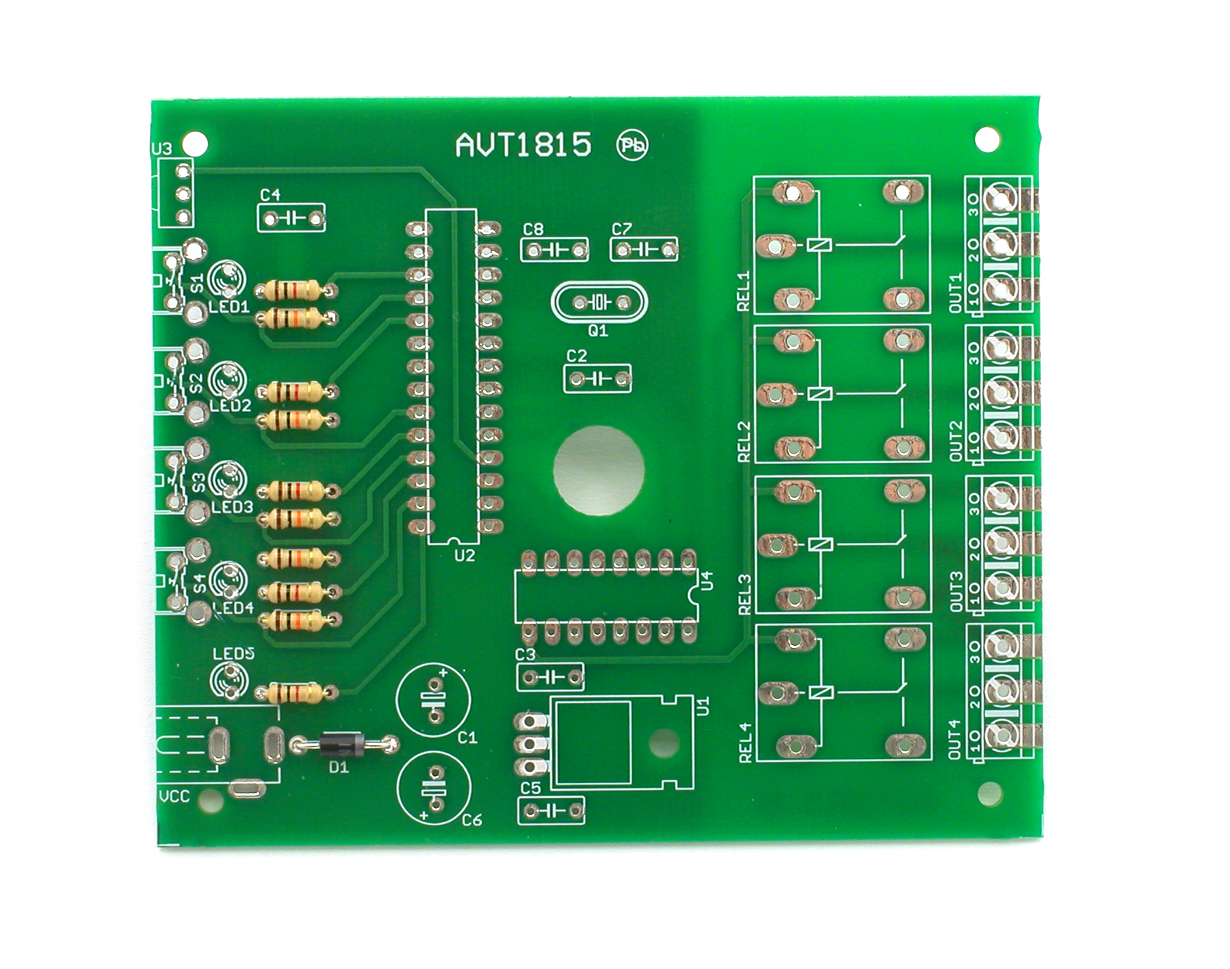
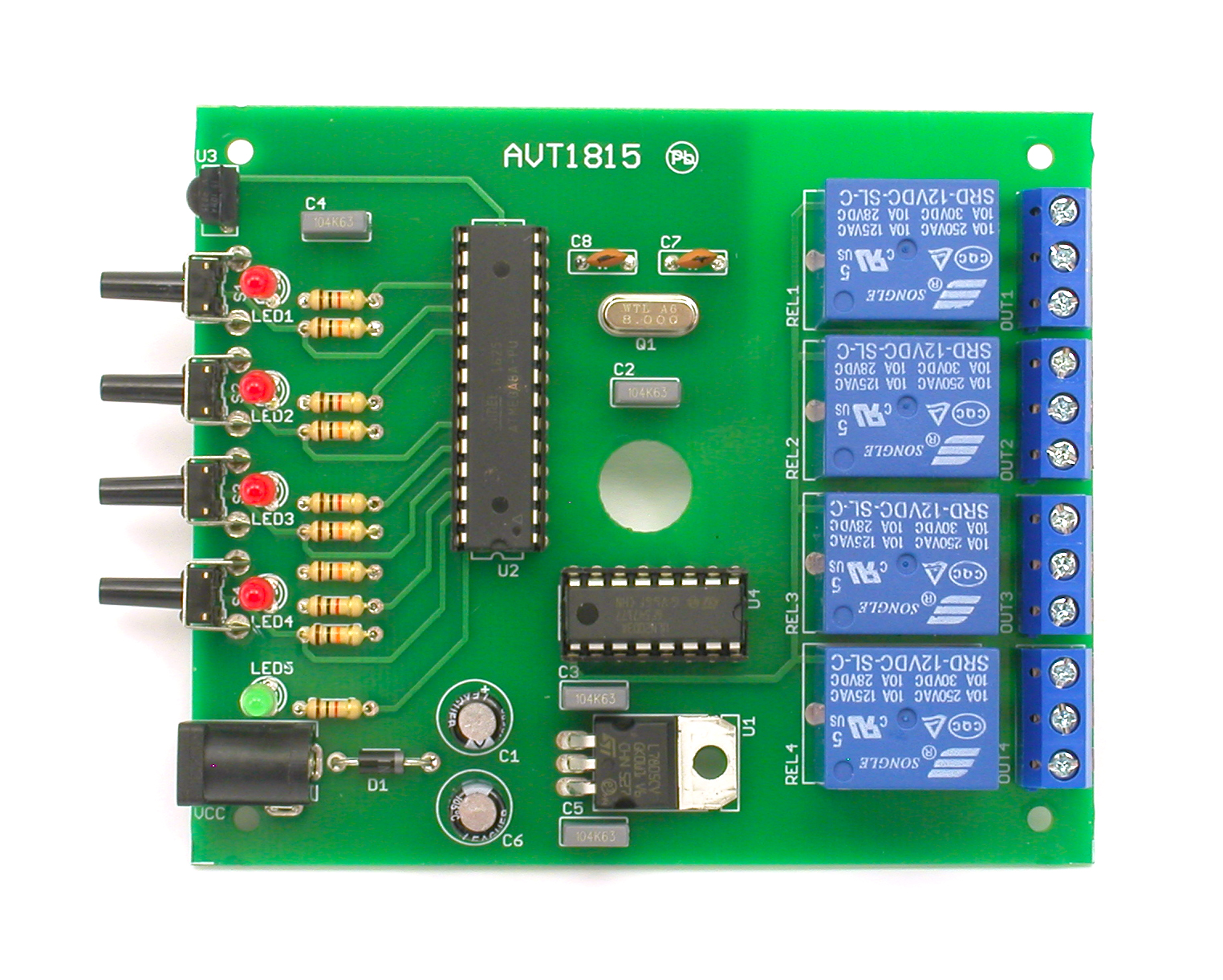
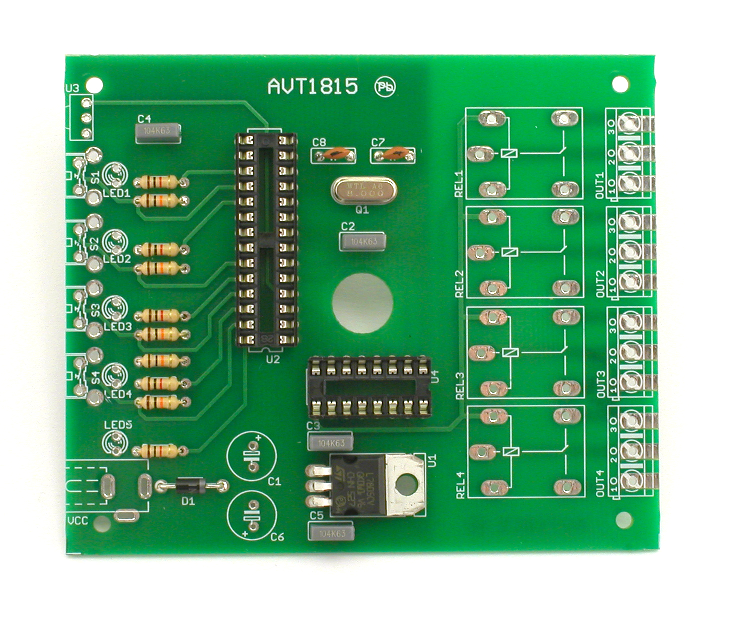
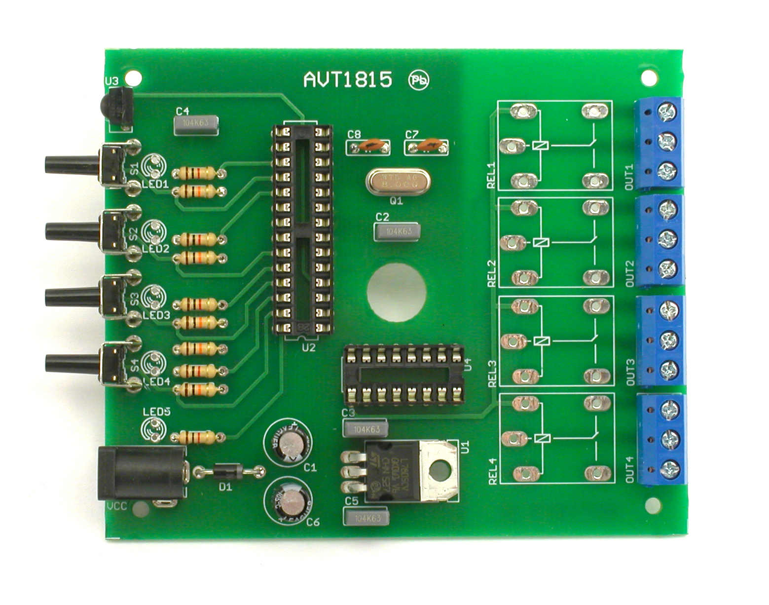
The assembly diagram is shown in Figure 2. The
assembly starts from the soldering the resistors
and other small components, and ending with
the assembly of electrolytic capacitors, relays
and screw terminals. The remote controlled
switch assembled from the tested components
does not require any adjustment and after
registering the commands sent by the IR
remote is ready for operation.
Entering the programming mode takes place
after pressing the corresponding button for
about 5 seconds. When it is done, the LED
corresponding to the programmed channel will
blink. This means that the switch is waiting to
receive and acknowledge the command from
the remote control that will be responsible for
switching the corresponding relay.
Correct reception of the remote command will
cause the LED to illuminate for a long time,
after which the LED blinking will indicate that
the switch is waiting for the confirmation of the
registered command. To do this, press the same
button again on the remote control. When the
correct command is received, the programming
procedure is completed and the switch returns
to normal operation. Entering the programming
mode is possible at any time during operation
of the device and is carried out independently
for each of the four channels.
Figure 1. Schematic diagram
AVT 1815
2
4-channel remote switch controlled by any
infrared remote control
DIFFICULTY
LEVEL
Assembly and test
7805
100uF
100nF100nF
+5V
GND
10k
GND
+5V
100uF
ATMEGA8
GND
100nF
GND
100nF
+12V
16MHz
22pF
22pF
1N4007 GND
VI
1
2
VO 3
U1
C6
C5C3
R1
OUT
VCC
GND
C1
U2
PB5(SCK) 19
PB7(XTAL2/TOSC2)
10
PB6(XTAL1/TOSC1)
9
GND
8
VCC
7
GND
22
AREF
21
AVCC
20
PB4(MISO) 18
PB3(MOSI/OC2) 17
PB2(SS/OC1B) 16
PB1(OC1A) 15
PB0(ICP) 14
PD7(AIN1) 13
PD6(AIN0) 12
PD5(T1) 11
PD4(XCK/T0) 6
PD3(INT1) 5
PD2(INT0) 4
PD1(TXD) 3
PD0(RXD) 2
PC5(ADC5/SCL) 28
PC4(ADC4/SDA) 27
PC3(ADC3) 26
PC2(ADC2) 25
PC1(ADC1) 24
PC0(ADC0) 23
PC6(/RESET)
1
C2
C4 Q1
VCC 1
2
3
C7
C8
D1
IR
IR
LED1
LED2
LED3
S1
S2
LED4
LED5
S3
S4
P1
P2
P3
P4
+
U3
+
1k
1k
1k
+5V
1k
1k
R6
R7
LED1
LED2
LED3
R8
LED4
R9
LED5
R10
LED1
LED2
LED3
LED4
LED5
GND
10k10k
+5V+5V
10k 10k
+5V +5V
+12V
1
2
S1
1
2
S2
R3R2
1
2
S3
1
2
S4
R4 R5
S1 S2 S3 S4
ULN2003AN
GND +12V
OUT1
OUT2
OUT3
OUT4
U4
I1
1
I2
2
I3
3
I4
4
I5
5
I6
6
I7
7
O1 16
O2 15
O3 14
O4 13
O5 12
O6 11
O7 10
CD+ 9
GND
8
21
REL1
21
REL2
21
REL3
21
REL4
P1
P2
P3
P4

U1
Component list
3
DIFFICULTY
LEVEL
Assembly in 4 steps
1
4
2
3
Solder resistors R1-R10 and diode D1
Solder relays REL1-REL4, LED diodes LED1-LED5,
insert chip into socket
Solder IC socket, capacitors C2-C5, C7, C8, crystal
and voltage stabilizer U1
Solder switch, connectors, capacitors C1, C6
and IR receiver U3
ZOOM
ZOOM
ZOOM
ZOOM
AVT 1815
C1
C6
U2
U4
1
U4: ...........................ULN2003 with 20-pin IC socket
Others:
LED1-LED5: ...........LED diode !
Capacitors:
C7, C8: ....................22pF (also marked as 22)
D1: ...........................1N4007 !
U1: ...........................7805 !
Q1: ...........................8MHz
S1-S4: .....................switch
Resistors:
C3-C5:.....................100nF (also marked as 104)
R1-R5:.....................10kΩ (brown-black-orange-gold)
C1, C6: ....................100µF !
Semiconductors:
U3: ...........................TSOP4836
U2: ...........................ATmega8 with 28-pin IC socket
R6 -R10: .................1kΩ (brown-black-red-gold)
OUT1-OUT4: ........3-pin terminal block connector
VCC:.........................power connector 2.1/5.5
REL1-REL4:............relay
While assembling the components marked
with an exclamation mark attention should
be paid to their polarity. Symbols of the
components on the PCB as well as photos of
assembled sets may come in useful. To access high-
resolution images, download the PDF file.
!
PDF DOWNLOAD
http://bit.ly/2KhhwA0
4-channel remote switch controlled by any
infrared remote control
LED1
LED2
LED3
LED4
LED5
AC
A
C
D1

4
DIFFICULTY
LEVEL
AVT 1815
4-channel remote switch controlled by any
infrared remote control
Educational Electronics Kits are intended for educational and demonstration purposes only. They are not intended
for use in commercial applications. If they are used in such applications the purchaser assumes all responsibility for
ensuring compliance with all local laws. In addition, they cannot be used as a part of life support systems, or systems
that for use as or as a part of life support systems, or systems that might create a hazardous situation of any kind.
!
Thank you for purchasing AVT product. Please take your time to read carefully the important information below
concering use of this product.
• If the kit is used to switch currents greater than 24V it is necessary to have the installation and performed by a
trained professional authorized for such work. The kit may only be used in such application if it was installed in a safe
to touch enclosure.
• Battery or wall-adaptor are safe devices. They do not require special attention unless main voltage is connected to
an output e.g. a relay.
• Never exceed the limits or ratings listed in the 'Specifications' section at the this user guide.
Failures in modern electronic component are very rare as 95% of non-working kits are due to poor soldering or
components placed in the wrong location or orientation so please check your work carefully.
• If the kit is used in schools or educational facilities or similar institutions the operation must be supervised by
trained and authorized staff.
• The product itself and all parts thereof (including packing material) are not suitable toys for childern! (choking
hazard, risk of electric shock, ...)
AVT SPV reserves the right to make changes without prior notice.
Assembly and connection of the device not in accordance with the instructions, unauthorized modification of components and any structural modifications may cause
damage to the device and endanger the person using it. In this case, the manufacturer and its authorized representatives shall not be liable for any damages arising directly
or indirectly from the use or malfunction of the product.
This symbol means do not dispose of your
product with your other household waste.
Instead, you should protect human health
and the environment by handing over your
waste equipment to a designated collection
point for the recycling of waste electrical
and electronic equipment.
Leszczynowa 11 Street,
03-197 Warsaw, Poland
http://avtkits.com/
AVT SPV Sp. z o.o.
Other AVT Switch manuals


